EP4000975B1 - Dispositif de chauffage et/ou de climatisation pour véhicule à moteur - Google Patents
Dispositif de chauffage et/ou de climatisation pour véhicule à moteur Download PDFInfo
- Publication number
- EP4000975B1 EP4000975B1 EP21207044.5A EP21207044A EP4000975B1 EP 4000975 B1 EP4000975 B1 EP 4000975B1 EP 21207044 A EP21207044 A EP 21207044A EP 4000975 B1 EP4000975 B1 EP 4000975B1
- Authority
- EP
- European Patent Office
- Prior art keywords
- air
- flap
- branch
- transmission
- tilting flap
- Prior art date
- Legal status (The legal status is an assumption and is not a legal conclusion. Google has not performed a legal analysis and makes no representation as to the accuracy of the status listed.)
- Active
Links
Images



Classifications
-
- B—PERFORMING OPERATIONS; TRANSPORTING
- B60—VEHICLES IN GENERAL
- B60H—ARRANGEMENTS OF HEATING, COOLING, VENTILATING OR OTHER AIR-TREATING DEVICES SPECIALLY ADAPTED FOR PASSENGER OR GOODS SPACES OF VEHICLES
- B60H1/00—Heating, cooling or ventilating devices
- B60H1/00642—Control systems or circuits; Control members or indication devices for heating, cooling or ventilating devices
- B60H1/00664—Construction or arrangement of damper doors
- B60H1/00671—Damper doors moved by rotation; Grilles
-
- B—PERFORMING OPERATIONS; TRANSPORTING
- B60—VEHICLES IN GENERAL
- B60H—ARRANGEMENTS OF HEATING, COOLING, VENTILATING OR OTHER AIR-TREATING DEVICES SPECIALLY ADAPTED FOR PASSENGER OR GOODS SPACES OF VEHICLES
- B60H1/00—Heating, cooling or ventilating devices
- B60H1/00642—Control systems or circuits; Control members or indication devices for heating, cooling or ventilating devices
- B60H1/00664—Construction or arrangement of damper doors
- B60H1/00692—Damper doors moved by translation, e.g. curtain doors
-
- B—PERFORMING OPERATIONS; TRANSPORTING
- B60—VEHICLES IN GENERAL
- B60H—ARRANGEMENTS OF HEATING, COOLING, VENTILATING OR OTHER AIR-TREATING DEVICES SPECIALLY ADAPTED FOR PASSENGER OR GOODS SPACES OF VEHICLES
- B60H1/00—Heating, cooling or ventilating devices
- B60H1/00642—Control systems or circuits; Control members or indication devices for heating, cooling or ventilating devices
- B60H1/00814—Control systems or circuits characterised by their output, for controlling particular components of the heating, cooling or ventilating installation
- B60H1/00821—Control systems or circuits characterised by their output, for controlling particular components of the heating, cooling or ventilating installation the components being ventilating, air admitting or air distributing devices
- B60H1/00835—Damper doors, e.g. position control
- B60H1/00857—Damper doors, e.g. position control characterised by the means connecting the initiating means, e.g. control lever, to the damper door
-
- B—PERFORMING OPERATIONS; TRANSPORTING
- B60—VEHICLES IN GENERAL
- B60H—ARRANGEMENTS OF HEATING, COOLING, VENTILATING OR OTHER AIR-TREATING DEVICES SPECIALLY ADAPTED FOR PASSENGER OR GOODS SPACES OF VEHICLES
- B60H1/00—Heating, cooling or ventilating devices
- B60H1/00642—Control systems or circuits; Control members or indication devices for heating, cooling or ventilating devices
- B60H1/00664—Construction or arrangement of damper doors
- B60H2001/00707—Details of pivots of damper doors
Definitions
- This invention relates to a heating and/or air conditioning device for a motor vehicle, comprising an air inlet for supplying air; an air transmission branch and an air heating branch, both supplied by the inlet duct and communicating with each other via a mixing zone; and mixing means configured to distribute an air flow between the air transfer branch and the air heating branch, wherein said mixing means are movable between two extreme positions comprising a closed position, wherein they prevent communication between the air inlet and the air heating branch and force the air flow to cross the air transmission branch, and an open position, wherein they prevent communication between the air inlet and the air transmission branch and force the air flow to cross the air heating branch.
- EP1826039A2 shows a device for air heating and conditioning comprising a tilting flap.
- the mixing means comprise flaps of different types, which are generally adapted to oscillate between two extreme positions, that is, an "all-hot” position and an “all-cold” position, and to occupy a plurality of intermediate positions.
- the treated air flow is generated by a fan located upstream of the air inlet.
- One object of this invention is to provide a heating and/or air conditioning device in which the movement areas of the flaps occupy as little space as possible to allow as much room as possible for the fluid veins (hot and cold) to meet for their proper mixing.
- a further object of this invention is to make available a flap configuration that is capable of working effectively even in the case in which the fan is placed extremely close to the air inlet.
- said mixing means comprise a tilting flap arranged between the air inlet and the air transmission and air heating branches, said tilting flap comprising a first end hinged to a sliding transmission member configured to drive the tilting flap and a second end guided by a sliding guide configured to orient the tilting flap relative to the air flow, wherein in said closed position the tilting flap closes an inlet of the air heating branch and deflects the air flow into the air transmission branch, and in said open position the tilting flap closes an inlet of the air transmission branch and deflects the air flow through the air heating branch, wherein
- the tilting flap it is possible to perform a movement of the tilting flap that is similar to that of a conventional swiveling flap, in that the tilting flap rotates around its second end but is different from the swiveling flap in that said second end is movable in a guided manner.
- a movement that starts from one end in a similar way to a swiveling flap, but then moves the tilting flap away from the air inlet and finally brings it close to this inlet when reaching the opposite end, again in a similar way to a swiveling flap.
- the arrangement described above allows the tilting flap to be moved as far as possible from the fan to avoid turbulence, vibration, and acoustic disaster, which would not be ensured by a conventional swiveling flap in the intermediate positions.
- sliding flaps allows for the least amount of space to be taken up with the movement areas of the flap, to allow as much space as possible for the fluid veins (hot and cold) to meet for their proper mixing.
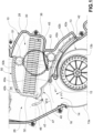
- the device depicted in the figures comprises a casing 10 delimiting an inlet duct adapted to be fed by an airflow (arrow F 1 ) driven by a centrifugal fan 13.
- the centrifugal fan 13 conventionally comprises an auger 13a and an impeller 13b housed in the auger 13a and driven by an electric motor (not shown).
- the fan 13 is in turn powered by an outer air flow drawn from outside the vehicle's passenger compartment, or by a recirculating air stream drawn from inside the passenger compartment.
- An evaporator (not shown) may be transversely housed in the inlet duct 12 connected to a conventional air conditioning circuit so as to produce an outflow of air that may be conditioned if the evaporator is active.
- the inlet duct Downstream, the inlet duct flows into a part of the air conditioning device dedicated to mixing hot and cold air veins. At the inlet of this mixing portion, the inlet duct therefore defines an air inlet 14 bounded by opposing walls 15 and 16 formed in the casing 10. As may be seen in the figures, the auger 13a of the fan 13 is directly connected to the air inlet 14.
- the air inlet 14 defines a confluence zone that feeds an air transmission branch 26 on one side, and an air heating branch 28 on the other side.
- the air heating branch 28 is delimited externally by a curved wall 30 of the casing and internally by an inner partition 32.
- the transmission branch 26 is delimited internally by the inner partition 32, and externally by an outer wall 33.
- the branches 26 and 28 communicate with each other on the one hand at the level of the confluence zone formed by the air inlet 14, and on the other hand at the level of another confluence zone 34, arranged downstream, which in the following will be referred to as the mixing zone.
- a heater 36 is housed in the heating branch 28.
- the mixing zone 34 conventionally communicates with various air distribution ducts (not shown) that are used to distribute the treated air to various areas within the vehicle.
- various air distribution ducts (not shown) that are used to distribute the treated air to various areas within the vehicle.
- air distribution ducts supplying vents used for windscreen defrosting/defogging of the motor vehicle, air distribution ducts supplying air vents in the lower part of the motor vehicle passenger compartment, air distribution ducts supplying air vents on the vehicle dashboard, and so on.
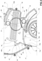
- a mixing group comprising a tilting flap 40 and a sliding flap 50 is mounted in the casing 10 at the mixing portion of the air conditioning device.
- the tilting flap 40 is arranged between the air inlet 14 and the air transmission and air heating branches 26, 28.
- the tilting flap 40 comprises a first end 40a, at an axis x1, hinged to a sliding transmission element 42.
- Said transmission element 42 is constrained, via a plurality of guided pins 42a, to a sliding guide (not shown) formed in the casing 10 of the air conditioning device.
- a rack 42b is formed on the transmission element 42.
- the transmission element 42 and the rack 42b extend in a curvilinear development, substantially conforming with the curvilinear development of the sliding guide.
- the transmission element 42 is configured to drive the tilting flap 40.
- the transmission element 42 is in turn driven by a gear wheel 43 that engages the rack 42b; more specifically, the transmission element 42 is driven by a plurality of gear wheels 43 mounted on the same shaft, the gear wheels of which respectively engage the racks 42b.
- the gear wheel 42 is then coupled, via a driven wheel 44 mounted on the same shaft as the gear wheel 42, to a drive wheel 45, the shaft of which is connected to an actuator (not shown).
- the tilting flap 40 comprises a second end 40b, opposite the first end 40a, which is guided by a sliding guide 46 configured to orient the tilting flap 40 with respect to the airflow.
- the sliding guide 46 extends, according to a curvilinear development, substantially in the direction of the air transmission branch 26 and is arranged in proximity to the inner partition 32.
- the second end 40b comprises a pin 47 engaging the slide rail 46; more specifically, the second end 40b comprises a pair of pins 47 engaging respective sliding guides 46 formed on opposite walls of the casing 10.
- the pin 47 defines a movable oscillation axis x2 of the tilting flap relative to the casing 10 of the air conditioning device.
- the tilting flap 40 Due to the driving action exerted via the transmission element 42, the tilting flap 40 is adapted to oscillate between two extreme positions:
- the transmission element 42 does not disturb the airflow or does so only insignificantly.
- the transmission element 42 In the "all-cold” position, the transmission element 42 is in effect retracted within a seat formed between the air inlet 14 and the air heating branch 28, in proximity to the first wall 15 of the air inlet 14. In the “all-hot” position, the transmission element 42 protrudes beyond this seat for a portion thereof having large windows, as may be seen in Fig. 4 and 5 .
- Fig. 2 shows an intermediate position of the tilting flap 40.
- the rotation induced by the drive element 42 in cooperation with the constraint provided by the sliding guide 46 also results in a displacement of the rotation axis x2 of the tilting flap 40; in the intermediate positions, therefore, the free end of the tilting flap 40 is moved away from the air inlet 14.
- the sliding flap 50 is arranged between the air heating branch 28 and the mixing zone 34.
- the sliding flap 50 is constrained to a sliding guide (not shown) formed in the casing 10 of the air conditioning device.
- a rack 50b is formed on the sliding flap 50.
- the sliding flap 50 and the rack 50b extend according to a curvilinear development, which is substantially in accordance with the curvilinear development of the sliding guide of the sliding flap 50.
- the sliding flap 50 is driven by a gear wheel 51 that engages the rack 50b; more specifically, the sliding flap 50 is driven by a plurality of gear wheels 51 mounted on the same shaft, said gear wheels respectively engaging the racks 50b.
- the gear wheel 51 is then coupled, via a driven wheel 54 mounted on the same shaft as the gear wheel 51, to the drive wheel 45.
- the sliding flap 50 is synchronously movable with the tilting flap 40.
- the sliding flap 50 closes an outlet of the air heating branch 28, and in the open position ( Fig. 3 ) the sliding door 50 opens the outlet of the air heating branch 28.
Landscapes
- Physics & Mathematics (AREA)
- Thermal Sciences (AREA)
- Engineering & Computer Science (AREA)
- Mechanical Engineering (AREA)
- Air-Conditioning For Vehicles (AREA)
Claims (6)
- Dispositif de chauffage et/ou de climatisation pour un véhicule à moteur comprenant une entrée d'air (14) pour une alimentation en air ; une branche de transmission d'air (26) et une branche de chauffage d'air (28), ces deux branches étant alimentées par l'entrée d'air (14) et communiquant l'une avec l'autre par l'intermédiaire d'une zone de mélange (34) ; et des moyens de mélange configurés pour distribuer un écoulement d'air entre la branche de transmission d'air (26) et la branche de chauffage d'air (28), lesdits moyens de mélange étant mobiles entre deux positions extrêmes comprenant une position fermée, à laquelle les moyens de mélange empêchent toute communication entre l'entrée d'air (14) et la branche de chauffage d'air (28) et forcent l'écoulement d'air à s'écouler à travers la branche de transmission d'air (26), et une position ouverte, à laquelle les moyens de mélange empêchent toute communication entre l'entrée d'air (14) et la branche de transmission d'air (26), et forcent l'écoulement d'air à s'écouler à travers la branche de chauffage d'air (28) ;lesdits moyens de mélange comprenant un volet basculant (40) agencé entre l'entrée d'air (14) et les branches de transmission d'air et de chauffage d'air (26, 28), ledit volet basculant comprenant une première extrémité (40a) articulée à un élément de transmission coulissant (42) configuré pour entraîner le volet basculant (40), et une deuxième extrémité (40b) guidée par un guide coulissant (46) configuré pour orienter le volet basculant (40) par rapport à l'écoulement d'air, à ladite position fermée, le volet basculant (40) fermant une entrée de la branche de chauffage d'air (28) et déviant l'écoulement d'air dans la branche de transmission d'air (26), et, à ladite position ouverte, le volet basculant (40) fermant une entrée de la branche de transmission d'air (26) et déviant l'écoulement d'air dans la branche de chauffage d'air (28),le dispositif étant caractérisé en ce queà ladite position fermée, la première extrémité (40a) du volet basculant (40) est en butée contre une première paroi (15) de l'entrée d'air (14), et la deuxième extrémité (40b) du volet basculant (40) est en butée contre une cloison intérieure (32) séparant la branche de chauffage d'air (28) de la branche de transmission d'air (26), età ladite position ouverte, la première extrémité (40a) du volet basculant (40) est en butée contre une deuxième paroi (16) de l'entrée d'air (14), à l'opposé de ladite première paroi (15), et la deuxième extrémité (40b) du volet basculant (40) est en butée contre ladite cloison intérieure (32).
- Dispositif selon la revendication 1, ledit guide coulissant (46) étant agencé à proximité de la cloison intérieure (32) et s'étendant le long de la branche de transmission d'air (26).
- Dispositif selon l'une quelconque des revendications précédentes, ledit élément de transmission (42) comprenant une crémaillère (42b) engagée par une roue dentée (43) configurée pour entraîner l'élément de transmission (42).
- Dispositif selon l'une quelconque des revendications précédentes, la deuxième extrémité (40b) du volet basculant (40) comprenant une broche (47) engageant un guide coulissant immobile (46).
- Dispositif selon l'une quelconque des revendications précédentes, comprenant en outre un volet coulissant (50) agencé entre la branche de chauffage d'air (28) et la zone de mélange (34), ledit volet coulissant (50) étant relié à l'élément de transmission (42) par l'intermédiaire d'une transmission (43, 45, 51), à ladite position fermée, le volet coulissant (50) fermant une sortie de la branche de chauffage d'air (28), et, à ladite position ouverte, le volet coulissant (50) ouvrant la sortie de la branche de chauffage d'air (28).
- Dispositif selon la revendication 5, ladite transmission comprenant au moins un engrenage.
Applications Claiming Priority (1)
| Application Number | Priority Date | Filing Date | Title |
|---|---|---|---|
| IT102020000027116A IT202000027116A1 (it) | 2020-11-12 | 2020-11-12 | Dispositivo di riscaldamento e/o climatizzazione per un autoveicolo |
Publications (2)
| Publication Number | Publication Date |
|---|---|
| EP4000975A1 EP4000975A1 (fr) | 2022-05-25 |
| EP4000975B1 true EP4000975B1 (fr) | 2023-07-19 |
Family
ID=74592389
Family Applications (1)
| Application Number | Title | Priority Date | Filing Date |
|---|---|---|---|
| EP21207044.5A Active EP4000975B1 (fr) | 2020-11-12 | 2021-11-09 | Dispositif de chauffage et/ou de climatisation pour véhicule à moteur |
Country Status (3)
| Country | Link |
|---|---|
| EP (1) | EP4000975B1 (fr) |
| ES (1) | ES2957769T3 (fr) |
| IT (1) | IT202000027116A1 (fr) |
Family Cites Families (3)
| Publication number | Priority date | Publication date | Assignee | Title |
|---|---|---|---|---|
| GB0603903D0 (en) * | 2006-02-28 | 2006-04-05 | Delphi Tech Inc | Variable flow valve |
| EP1925474A1 (fr) * | 2006-11-24 | 2008-05-28 | DENSO THERMAL SYSTEMS S.p.A. | Système de traitement d'un flux d'air |
| FR3054490B1 (fr) * | 2016-07-28 | 2019-04-19 | Valeo Systemes Thermiques | Dispositif de chauffage, ventilation et/ou climatisation pour vehicule automobile |
-
2020
- 2020-11-12 IT IT102020000027116A patent/IT202000027116A1/it unknown
-
2021
- 2021-11-09 ES ES21207044T patent/ES2957769T3/es active Active
- 2021-11-09 EP EP21207044.5A patent/EP4000975B1/fr active Active
Also Published As
| Publication number | Publication date |
|---|---|
| ES2957769T3 (es) | 2024-01-25 |
| IT202000027116A1 (it) | 2022-05-12 |
| EP4000975A1 (fr) | 2022-05-25 |
Similar Documents
| Publication | Publication Date | Title |
|---|---|---|
| US6347988B1 (en) | Slide door unit for use in automotive air conditioner | |
| US8292704B2 (en) | Motor-vehicle dashboard with main central portion having no outflow apertures for the ventilation air | |
| US11214113B2 (en) | Vehicular air conditioning device | |
| US20170129312A1 (en) | Air blowing device | |
| JP2002339899A (ja) | 遠心式送風機 | |
| WO2018112314A1 (fr) | Système cvca | |
| US20130149953A1 (en) | Vehicular air conditioning apparatus | |
| CN112440681A (zh) | 车辆的空调出风结构、车辆空调系统及车辆 | |
| CN104002636B (zh) | 车辆用空调装置 | |
| EP3335918A1 (fr) | Dispositif de soufflage d'air | |
| EP4000975B1 (fr) | Dispositif de chauffage et/ou de climatisation pour véhicule à moteur | |
| EP1835827A1 (fr) | Porte de regulation d'air avec element de stratification integre | |
| JPWO2007061039A1 (ja) | 自動車用空気調和装置 | |
| WO2015115058A1 (fr) | Dispositif de conditionnement d'air pour véhicule | |
| EP4420903A1 (fr) | Dispositif de climatisation pour véhicule | |
| CN112368162A (zh) | 要被安装在机动车辆门上的壳体以及包括这种壳体的门 | |
| JP6054191B2 (ja) | 空調ユニット用ドア構造および空調ユニット | |
| CN112004715A (zh) | 具有扩展的通风的车辆 | |
| JP5327161B2 (ja) | 内外気切替装置 | |
| KR20070068568A (ko) | 차량용 공조장치의 덕트 분지 구조 | |
| EP1826039B1 (fr) | Soupape à débit variable | |
| EP4470808B1 (fr) | Dispositif de chauffage et/ou de climatisation pour véhicule automobile | |
| EP4424533A1 (fr) | Unité de climatisation pour un véhicule automobile, comprenant une porte avec un passage d'air de dérivation | |
| KR101566307B1 (ko) | 차량용 후석 공조장치 | |
| US20250353353A1 (en) | Hvac air inlet system |
Legal Events
| Date | Code | Title | Description |
|---|---|---|---|
| PUAI | Public reference made under article 153(3) epc to a published international application that has entered the european phase |
Free format text: ORIGINAL CODE: 0009012 |
|
| STAA | Information on the status of an ep patent application or granted ep patent |
Free format text: STATUS: THE APPLICATION HAS BEEN PUBLISHED |
|
| AK | Designated contracting states |
Kind code of ref document: A1 Designated state(s): AL AT BE BG CH CY CZ DE DK EE ES FI FR GB GR HR HU IE IS IT LI LT LU LV MC MK MT NL NO PL PT RO RS SE SI SK SM TR |
|
| STAA | Information on the status of an ep patent application or granted ep patent |
Free format text: STATUS: REQUEST FOR EXAMINATION WAS MADE |
|
| 17P | Request for examination filed |
Effective date: 20220930 |
|
| RBV | Designated contracting states (corrected) |
Designated state(s): AL AT BE BG CH CY CZ DE DK EE ES FI FR GB GR HR HU IE IS IT LI LT LU LV MC MK MT NL NO PL PT RO RS SE SI SK SM TR |
|
| GRAP | Despatch of communication of intention to grant a patent |
Free format text: ORIGINAL CODE: EPIDOSNIGR1 |
|
| STAA | Information on the status of an ep patent application or granted ep patent |
Free format text: STATUS: GRANT OF PATENT IS INTENDED |
|
| RIC1 | Information provided on ipc code assigned before grant |
Ipc: B60H 1/00 20060101AFI20230201BHEP |
|
| INTG | Intention to grant announced |
Effective date: 20230217 |
|
| RAP3 | Party data changed (applicant data changed or rights of an application transferred) |
Owner name: DENSO THERMAL SYSTEMS S.P.A. |
|
| GRAS | Grant fee paid |
Free format text: ORIGINAL CODE: EPIDOSNIGR3 |
|
| GRAA | (expected) grant |
Free format text: ORIGINAL CODE: 0009210 |
|
| STAA | Information on the status of an ep patent application or granted ep patent |
Free format text: STATUS: THE PATENT HAS BEEN GRANTED |
|
| AK | Designated contracting states |
Kind code of ref document: B1 Designated state(s): AL AT BE BG CH CY CZ DE DK EE ES FI FR GB GR HR HU IE IS IT LI LT LU LV MC MK MT NL NO PL PT RO RS SE SI SK SM TR |
|
| REG | Reference to a national code |
Ref country code: GB Ref legal event code: FG4D |
|
| REG | Reference to a national code |
Ref country code: CH Ref legal event code: EP |
|
| REG | Reference to a national code |
Ref country code: DE Ref legal event code: R096 Ref document number: 602021003599 Country of ref document: DE |
|
| REG | Reference to a national code |
Ref country code: IE Ref legal event code: FG4D |
|
| REG | Reference to a national code |
Ref country code: LT Ref legal event code: MG9D |
|
| REG | Reference to a national code |
Ref country code: NL Ref legal event code: MP Effective date: 20230719 |
|
| REG | Reference to a national code |
Ref country code: AT Ref legal event code: MK05 Ref document number: 1589119 Country of ref document: AT Kind code of ref document: T Effective date: 20230719 |
|
| PG25 | Lapsed in a contracting state [announced via postgrant information from national office to epo] |
Ref country code: NL Free format text: LAPSE BECAUSE OF FAILURE TO SUBMIT A TRANSLATION OF THE DESCRIPTION OR TO PAY THE FEE WITHIN THE PRESCRIBED TIME-LIMIT Effective date: 20230719 |
|
| PG25 | Lapsed in a contracting state [announced via postgrant information from national office to epo] |
Ref country code: GR Free format text: LAPSE BECAUSE OF FAILURE TO SUBMIT A TRANSLATION OF THE DESCRIPTION OR TO PAY THE FEE WITHIN THE PRESCRIBED TIME-LIMIT Effective date: 20231020 |
|
| PG25 | Lapsed in a contracting state [announced via postgrant information from national office to epo] |
Ref country code: IS Free format text: LAPSE BECAUSE OF FAILURE TO SUBMIT A TRANSLATION OF THE DESCRIPTION OR TO PAY THE FEE WITHIN THE PRESCRIBED TIME-LIMIT Effective date: 20231119 |
|
| REG | Reference to a national code |
Ref country code: ES Ref legal event code: FG2A Ref document number: 2957769 Country of ref document: ES Kind code of ref document: T3 Effective date: 20240125 |
|
| PG25 | Lapsed in a contracting state [announced via postgrant information from national office to epo] |
Ref country code: SE Free format text: LAPSE BECAUSE OF FAILURE TO SUBMIT A TRANSLATION OF THE DESCRIPTION OR TO PAY THE FEE WITHIN THE PRESCRIBED TIME-LIMIT Effective date: 20230719 Ref country code: RS Free format text: LAPSE BECAUSE OF FAILURE TO SUBMIT A TRANSLATION OF THE DESCRIPTION OR TO PAY THE FEE WITHIN THE PRESCRIBED TIME-LIMIT Effective date: 20230719 Ref country code: PT Free format text: LAPSE BECAUSE OF FAILURE TO SUBMIT A TRANSLATION OF THE DESCRIPTION OR TO PAY THE FEE WITHIN THE PRESCRIBED TIME-LIMIT Effective date: 20231120 Ref country code: NO Free format text: LAPSE BECAUSE OF FAILURE TO SUBMIT A TRANSLATION OF THE DESCRIPTION OR TO PAY THE FEE WITHIN THE PRESCRIBED TIME-LIMIT Effective date: 20231019 Ref country code: LV Free format text: LAPSE BECAUSE OF FAILURE TO SUBMIT A TRANSLATION OF THE DESCRIPTION OR TO PAY THE FEE WITHIN THE PRESCRIBED TIME-LIMIT Effective date: 20230719 Ref country code: LT Free format text: LAPSE BECAUSE OF FAILURE TO SUBMIT A TRANSLATION OF THE DESCRIPTION OR TO PAY THE FEE WITHIN THE PRESCRIBED TIME-LIMIT Effective date: 20230719 Ref country code: IS Free format text: LAPSE BECAUSE OF FAILURE TO SUBMIT A TRANSLATION OF THE DESCRIPTION OR TO PAY THE FEE WITHIN THE PRESCRIBED TIME-LIMIT Effective date: 20231119 Ref country code: HR Free format text: LAPSE BECAUSE OF FAILURE TO SUBMIT A TRANSLATION OF THE DESCRIPTION OR TO PAY THE FEE WITHIN THE PRESCRIBED TIME-LIMIT Effective date: 20230719 Ref country code: GR Free format text: LAPSE BECAUSE OF FAILURE TO SUBMIT A TRANSLATION OF THE DESCRIPTION OR TO PAY THE FEE WITHIN THE PRESCRIBED TIME-LIMIT Effective date: 20231020 Ref country code: FI Free format text: LAPSE BECAUSE OF FAILURE TO SUBMIT A TRANSLATION OF THE DESCRIPTION OR TO PAY THE FEE WITHIN THE PRESCRIBED TIME-LIMIT Effective date: 20230719 Ref country code: AT Free format text: LAPSE BECAUSE OF FAILURE TO SUBMIT A TRANSLATION OF THE DESCRIPTION OR TO PAY THE FEE WITHIN THE PRESCRIBED TIME-LIMIT Effective date: 20230719 |
|
| PG25 | Lapsed in a contracting state [announced via postgrant information from national office to epo] |
Ref country code: PL Free format text: LAPSE BECAUSE OF FAILURE TO SUBMIT A TRANSLATION OF THE DESCRIPTION OR TO PAY THE FEE WITHIN THE PRESCRIBED TIME-LIMIT Effective date: 20230719 |
|
| REG | Reference to a national code |
Ref country code: DE Ref legal event code: R097 Ref document number: 602021003599 Country of ref document: DE |
|
| PG25 | Lapsed in a contracting state [announced via postgrant information from national office to epo] |
Ref country code: SM Free format text: LAPSE BECAUSE OF FAILURE TO SUBMIT A TRANSLATION OF THE DESCRIPTION OR TO PAY THE FEE WITHIN THE PRESCRIBED TIME-LIMIT Effective date: 20230719 Ref country code: RO Free format text: LAPSE BECAUSE OF FAILURE TO SUBMIT A TRANSLATION OF THE DESCRIPTION OR TO PAY THE FEE WITHIN THE PRESCRIBED TIME-LIMIT Effective date: 20230719 Ref country code: EE Free format text: LAPSE BECAUSE OF FAILURE TO SUBMIT A TRANSLATION OF THE DESCRIPTION OR TO PAY THE FEE WITHIN THE PRESCRIBED TIME-LIMIT Effective date: 20230719 Ref country code: DK Free format text: LAPSE BECAUSE OF FAILURE TO SUBMIT A TRANSLATION OF THE DESCRIPTION OR TO PAY THE FEE WITHIN THE PRESCRIBED TIME-LIMIT Effective date: 20230719 Ref country code: CZ Free format text: LAPSE BECAUSE OF FAILURE TO SUBMIT A TRANSLATION OF THE DESCRIPTION OR TO PAY THE FEE WITHIN THE PRESCRIBED TIME-LIMIT Effective date: 20230719 Ref country code: SK Free format text: LAPSE BECAUSE OF FAILURE TO SUBMIT A TRANSLATION OF THE DESCRIPTION OR TO PAY THE FEE WITHIN THE PRESCRIBED TIME-LIMIT Effective date: 20230719 |
|
| PLBE | No opposition filed within time limit |
Free format text: ORIGINAL CODE: 0009261 |
|
| STAA | Information on the status of an ep patent application or granted ep patent |
Free format text: STATUS: NO OPPOSITION FILED WITHIN TIME LIMIT |
|
| PG25 | Lapsed in a contracting state [announced via postgrant information from national office to epo] |
Ref country code: IT Free format text: LAPSE BECAUSE OF FAILURE TO SUBMIT A TRANSLATION OF THE DESCRIPTION OR TO PAY THE FEE WITHIN THE PRESCRIBED TIME-LIMIT Effective date: 20230719 |
|
| 26N | No opposition filed |
Effective date: 20240422 |
|
| PG25 | Lapsed in a contracting state [announced via postgrant information from national office to epo] |
Ref country code: MC Free format text: LAPSE BECAUSE OF FAILURE TO SUBMIT A TRANSLATION OF THE DESCRIPTION OR TO PAY THE FEE WITHIN THE PRESCRIBED TIME-LIMIT Effective date: 20230719 |
|
| PG25 | Lapsed in a contracting state [announced via postgrant information from national office to epo] |
Ref country code: LU Free format text: LAPSE BECAUSE OF NON-PAYMENT OF DUE FEES Effective date: 20231109 |
|
| PG25 | Lapsed in a contracting state [announced via postgrant information from national office to epo] |
Ref country code: MC Free format text: LAPSE BECAUSE OF FAILURE TO SUBMIT A TRANSLATION OF THE DESCRIPTION OR TO PAY THE FEE WITHIN THE PRESCRIBED TIME-LIMIT Effective date: 20230719 Ref country code: LU Free format text: LAPSE BECAUSE OF NON-PAYMENT OF DUE FEES Effective date: 20231109 Ref country code: SI Free format text: LAPSE BECAUSE OF FAILURE TO SUBMIT A TRANSLATION OF THE DESCRIPTION OR TO PAY THE FEE WITHIN THE PRESCRIBED TIME-LIMIT Effective date: 20230719 |
|
| REG | Reference to a national code |
Ref country code: BE Ref legal event code: MM Effective date: 20231130 |
|
| REG | Reference to a national code |
Ref country code: IE Ref legal event code: MM4A |
|
| PG25 | Lapsed in a contracting state [announced via postgrant information from national office to epo] |
Ref country code: IE Free format text: LAPSE BECAUSE OF NON-PAYMENT OF DUE FEES Effective date: 20231109 |
|
| PG25 | Lapsed in a contracting state [announced via postgrant information from national office to epo] |
Ref country code: BE Free format text: LAPSE BECAUSE OF NON-PAYMENT OF DUE FEES Effective date: 20231130 |
|
| PG25 | Lapsed in a contracting state [announced via postgrant information from national office to epo] |
Ref country code: IE Free format text: LAPSE BECAUSE OF NON-PAYMENT OF DUE FEES Effective date: 20231109 Ref country code: BE Free format text: LAPSE BECAUSE OF NON-PAYMENT OF DUE FEES Effective date: 20231130 |
|
| PG25 | Lapsed in a contracting state [announced via postgrant information from national office to epo] |
Ref country code: BG Free format text: LAPSE BECAUSE OF FAILURE TO SUBMIT A TRANSLATION OF THE DESCRIPTION OR TO PAY THE FEE WITHIN THE PRESCRIBED TIME-LIMIT Effective date: 20230719 |
|
| PG25 | Lapsed in a contracting state [announced via postgrant information from national office to epo] |
Ref country code: BG Free format text: LAPSE BECAUSE OF FAILURE TO SUBMIT A TRANSLATION OF THE DESCRIPTION OR TO PAY THE FEE WITHIN THE PRESCRIBED TIME-LIMIT Effective date: 20230719 |
|
| REG | Reference to a national code |
Ref country code: CH Ref legal event code: PL |
|
| REG | Reference to a national code |
Ref country code: CH Ref legal event code: PL |
|
| PG25 | Lapsed in a contracting state [announced via postgrant information from national office to epo] |
Ref country code: CH Free format text: LAPSE BECAUSE OF NON-PAYMENT OF DUE FEES Effective date: 20241130 |
|
| PG25 | Lapsed in a contracting state [announced via postgrant information from national office to epo] |
Ref country code: CY Free format text: LAPSE BECAUSE OF FAILURE TO SUBMIT A TRANSLATION OF THE DESCRIPTION OR TO PAY THE FEE WITHIN THE PRESCRIBED TIME-LIMIT; INVALID AB INITIO Effective date: 20211109 |
|
| PG25 | Lapsed in a contracting state [announced via postgrant information from national office to epo] |
Ref country code: TR Free format text: LAPSE BECAUSE OF FAILURE TO SUBMIT A TRANSLATION OF THE DESCRIPTION OR TO PAY THE FEE WITHIN THE PRESCRIBED TIME-LIMIT Effective date: 20230719 |
|
| PGFP | Annual fee paid to national office [announced via postgrant information from national office to epo] |
Ref country code: DE Payment date: 20251125 Year of fee payment: 5 |
|
| PGFP | Annual fee paid to national office [announced via postgrant information from national office to epo] |
Ref country code: FR Payment date: 20251107 Year of fee payment: 5 |
|
| PGFP | Annual fee paid to national office [announced via postgrant information from national office to epo] |
Ref country code: ES Payment date: 20251201 Year of fee payment: 5 |
|
| PG25 | Lapsed in a contracting state [announced via postgrant information from national office to epo] |
Ref country code: HU Free format text: LAPSE BECAUSE OF FAILURE TO SUBMIT A TRANSLATION OF THE DESCRIPTION OR TO PAY THE FEE WITHIN THE PRESCRIBED TIME-LIMIT; INVALID AB INITIO Effective date: 20211109 |