EP4000978A1 - Agencement de montage de bloc-batterie pour un véhicule électrique de chargement - Google Patents
Agencement de montage de bloc-batterie pour un véhicule électrique de chargement Download PDFInfo
- Publication number
- EP4000978A1 EP4000978A1 EP21205029.8A EP21205029A EP4000978A1 EP 4000978 A1 EP4000978 A1 EP 4000978A1 EP 21205029 A EP21205029 A EP 21205029A EP 4000978 A1 EP4000978 A1 EP 4000978A1
- Authority
- EP
- European Patent Office
- Prior art keywords
- battery pack
- brackets
- cargo
- mounting arrangement
- vehicle
- Prior art date
- Legal status (The legal status is an assumption and is not a legal conclusion. Google has not performed a legal analysis and makes no representation as to the accuracy of the status listed.)
- Pending
Links
- 210000002105 tongue Anatomy 0.000 claims description 54
- 238000003466 welding Methods 0.000 claims description 13
- 230000005484 gravity Effects 0.000 claims description 5
- 230000000295 complement effect Effects 0.000 claims description 3
- 238000010276 construction Methods 0.000 claims description 3
- 230000003014 reinforcing effect Effects 0.000 claims description 3
- 238000000034 method Methods 0.000 description 13
- 238000004519 manufacturing process Methods 0.000 description 8
- 239000002184 metal Substances 0.000 description 6
- 238000012986 modification Methods 0.000 description 4
- 230000004048 modification Effects 0.000 description 4
- 108091035710 E-box Proteins 0.000 description 3
- 230000000712 assembly Effects 0.000 description 3
- 238000000429 assembly Methods 0.000 description 3
- 239000002828 fuel tank Substances 0.000 description 3
- 238000004891 communication Methods 0.000 description 2
- 238000013461 design Methods 0.000 description 2
- 239000000725 suspension Substances 0.000 description 2
- 230000006978 adaptation Effects 0.000 description 1
- 238000002485 combustion reaction Methods 0.000 description 1
- 239000004615 ingredient Substances 0.000 description 1
- 230000002093 peripheral effect Effects 0.000 description 1
- 238000012545 processing Methods 0.000 description 1
- GOLXNESZZPUPJE-UHFFFAOYSA-N spiromesifen Chemical compound CC1=CC(C)=CC(C)=C1C(C(O1)=O)=C(OC(=O)CC(C)(C)C)C11CCCC1 GOLXNESZZPUPJE-UHFFFAOYSA-N 0.000 description 1
Images










Classifications
-
- B—PERFORMING OPERATIONS; TRANSPORTING
- B60—VEHICLES IN GENERAL
- B60K—ARRANGEMENT OR MOUNTING OF PROPULSION UNITS OR OF TRANSMISSIONS IN VEHICLES; ARRANGEMENT OR MOUNTING OF PLURAL DIVERSE PRIME-MOVERS IN VEHICLES; AUXILIARY DRIVES FOR VEHICLES; INSTRUMENTATION OR DASHBOARDS FOR VEHICLES; ARRANGEMENTS IN CONNECTION WITH COOLING, AIR INTAKE, GAS EXHAUST OR FUEL SUPPLY OF PROPULSION UNITS IN VEHICLES
- B60K1/00—Arrangement or mounting of electrical propulsion units
- B60K1/04—Arrangement or mounting of electrical propulsion units of the electric storage means for propulsion
-
- B—PERFORMING OPERATIONS; TRANSPORTING
- B62—LAND VEHICLES FOR TRAVELLING OTHERWISE THAN ON RAILS
- B62D—MOTOR VEHICLES; TRAILERS
- B62D21/00—Understructures, i.e. chassis frame on which a vehicle body may be mounted
- B62D21/02—Understructures, i.e. chassis frame on which a vehicle body may be mounted comprising longitudinally or transversely arranged frame members
-
- B—PERFORMING OPERATIONS; TRANSPORTING
- B62—LAND VEHICLES FOR TRAVELLING OTHERWISE THAN ON RAILS
- B62D—MOTOR VEHICLES; TRAILERS
- B62D21/00—Understructures, i.e. chassis frame on which a vehicle body may be mounted
- B62D21/09—Means for mounting load bearing surfaces
-
- B—PERFORMING OPERATIONS; TRANSPORTING
- B60—VEHICLES IN GENERAL
- B60K—ARRANGEMENT OR MOUNTING OF PROPULSION UNITS OR OF TRANSMISSIONS IN VEHICLES; ARRANGEMENT OR MOUNTING OF PLURAL DIVERSE PRIME-MOVERS IN VEHICLES; AUXILIARY DRIVES FOR VEHICLES; INSTRUMENTATION OR DASHBOARDS FOR VEHICLES; ARRANGEMENTS IN CONNECTION WITH COOLING, AIR INTAKE, GAS EXHAUST OR FUEL SUPPLY OF PROPULSION UNITS IN VEHICLES
- B60K1/00—Arrangement or mounting of electrical propulsion units
- B60K1/04—Arrangement or mounting of electrical propulsion units of the electric storage means for propulsion
- B60K2001/0405—Arrangement or mounting of electrical propulsion units of the electric storage means for propulsion characterised by their position
-
- B—PERFORMING OPERATIONS; TRANSPORTING
- B60—VEHICLES IN GENERAL
- B60K—ARRANGEMENT OR MOUNTING OF PROPULSION UNITS OR OF TRANSMISSIONS IN VEHICLES; ARRANGEMENT OR MOUNTING OF PLURAL DIVERSE PRIME-MOVERS IN VEHICLES; AUXILIARY DRIVES FOR VEHICLES; INSTRUMENTATION OR DASHBOARDS FOR VEHICLES; ARRANGEMENTS IN CONNECTION WITH COOLING, AIR INTAKE, GAS EXHAUST OR FUEL SUPPLY OF PROPULSION UNITS IN VEHICLES
- B60K1/00—Arrangement or mounting of electrical propulsion units
- B60K1/04—Arrangement or mounting of electrical propulsion units of the electric storage means for propulsion
- B60K2001/0405—Arrangement or mounting of electrical propulsion units of the electric storage means for propulsion characterised by their position
- B60K2001/0416—Arrangement in the rear part of the vehicle
-
- B—PERFORMING OPERATIONS; TRANSPORTING
- B60—VEHICLES IN GENERAL
- B60K—ARRANGEMENT OR MOUNTING OF PROPULSION UNITS OR OF TRANSMISSIONS IN VEHICLES; ARRANGEMENT OR MOUNTING OF PLURAL DIVERSE PRIME-MOVERS IN VEHICLES; AUXILIARY DRIVES FOR VEHICLES; INSTRUMENTATION OR DASHBOARDS FOR VEHICLES; ARRANGEMENTS IN CONNECTION WITH COOLING, AIR INTAKE, GAS EXHAUST OR FUEL SUPPLY OF PROPULSION UNITS IN VEHICLES
- B60K1/00—Arrangement or mounting of electrical propulsion units
- B60K1/04—Arrangement or mounting of electrical propulsion units of the electric storage means for propulsion
- B60K2001/0405—Arrangement or mounting of electrical propulsion units of the electric storage means for propulsion characterised by their position
- B60K2001/0444—Arrangement on a trailer
-
- B—PERFORMING OPERATIONS; TRANSPORTING
- B60—VEHICLES IN GENERAL
- B60Y—INDEXING SCHEME RELATING TO ASPECTS CROSS-CUTTING VEHICLE TECHNOLOGY
- B60Y2200/00—Type of vehicle
- B60Y2200/10—Road Vehicles
- B60Y2200/12—Motorcycles, Trikes; Quads; Scooters
Definitions
- the present disclosure relates to mounting arrangements of battery packs in vehicles. Particularly, the present disclosure relates to mounting arrangements of battery packs in cargo electric vehicles.
- the weight of an electrochemical battery pack is significant, and can be almost one-third of the unloaded weight of an electrical vehicle. Therefore, it is required that the battery pack is positioned on the chassis of the vehicle such that there is minimum challenge from balancing as well as ride and handling point of view of the vehicle.
- a primary object of the present disclosure is to provide a battery pack mounting arrangement for a cargo electric vehicle.
- Another object of the present disclosure is to provide a battery pack mounting arrangement for a cargo electric vehicle, which ensures good balancing as well as ride and handling characteristics of the vehicle.
- Yet another object of the present disclosure is to provide a battery pack mounting arrangement for a cargo electric vehicle, which ensures maximum space is available for loading cargo.
- Still another object of the present disclosure is to provide a battery pack mounting arrangement for a cargo electric vehicle, which ensures driver safety.
- Yet another object of the present disclosure is to provide a battery pack mounting arrangement for a cargo electric vehicle, which is ease of assembly.
- the present disclosure envisages a battery pack mounting arrangement for a cargo electrical vehicle.
- the vehicle is defined by a cabin and a cargo section operatively behind the cabin.
- the cargo section is supported on a chassis defined by a pair of long members spaced apart from each other and cross members spanning the long members transversely.
- the cargo section is defined by a cargo tray.
- the mounting arrangement comprises a battery case, a first set of brackets, a second set of brackets and a set of fasteners.
- the battery case houses the battery pack and is configured to be nested in the cargo section in a space defined by the space between the long members, a wall of the cabin and a first cross member.
- the first set of brackets is weldable to the outer surface of the opposite walls of the battery case in a predetermined spaced apart distance (d).
- the second set of brackets is weldable to the long members and is spaced apart with respect to each other at a distance (D) and is complementary to the first set of brackets in the operative configuration of the arrangement.
- Tongues extend from the first set of brackets and the second set of brackets.
- the tongues of the first set of brackets and the tongues of the second set of brackets overlap each other such that the first set of brackets rests on the second set of brackets on either side of the battery case.
- a first set of apertures is provided on the tongues in the first set of brackets.
- a second set of apertures is provided on the tongues in the second set of brackets.
- the first set of apertures and the second set of apertures are configured to be aligned to each other along common axes when the first set of tongues is supported on the second set of tongues in an operative configuration of the arrangement.
- the set of fasteners is configured to fasten the first set of brackets to the second set of brackets via the first set of apertures and the second set of apertures for mounting the battery pack in a nested configuration in the cargo section in the space.
- a nut is fixed by welding, on the operative lower surface of the first tongue.
- the nut is aligned with the first aperture for receiving the fastener.
- the second set of brackets is fixed on the surface of the battery case of the battery pack with the shortest width.
- each of the first brackets is L-shaped, has a case-side wall weldable to the battery case and is provided with reinforcing ribs.
- the first tongue of the first bracket extends from the case-side wall towards an operatively outer side of the battery case.
- each of the second brackets has an overlapping portion weldable to a long member and is shaped to overlap an operative top surface of the long member.
- the second tongue of the second bracket extends from the overlapping portion towards an operatively inner side of the corresponding long member relative to the vehicle.
- the battery pack mounting arrangement comprises four first brackets and four second brackets.
- the battery pack is disposed at an operative front extreme position between the long members.
- the battery pack is disposed below the cargo tray.
- the battery pack is disposed below the bed of the cargo tray.
- each of the long members has a box-type construction and a majority of the area of the lateral surfaces of the battery pack is covered by the lateral surfaces of the long members on either side.
- the centre of gravity of the battery pack lies within a space between the lateral surfaces of the long members.
- the battery pack is disposed to have the longest dimension of the battery pack extend in a lateral axis of the vehicle.
- the battery case has a rectangular cross-section.
- the first set of brackets is spaced apart from corners of the battery case.
- the ratio of the centre distance between the apertures to the width of the battery case ranges between 0.6 and 0.95.
- each of the first brackets is folded from a single first blank. Thickness of the first blank ranges between 2mm and 4mm.
- each of the second brackets is folded from a single second blank. Thickness of the second blank ranges between 2mm and 4 mm.
- Centre of the first aperture is 41.7 mm away from the lateral edge of the first tongue, and ratio of the diameter of the first aperture to the distance of the centre of the first aperture from the lateral edge of the first tongue ranges between 0.1 and 0.5.
- centre of the second aperture is 17 mm away from the lateral edge of the second tongue, and ratio of the diameter of the second aperture to the distance of the centre of the second aperture from the lateral edge of the second tongue ranges between 0.15 and 1.
- the present disclosure also envisages a cargo electrical vehicle comprising a cabin, a cargo section arranged behind the cabin and defined by a cargo tray, a battery pack and a battery pack mounting arrangement.
- the cargo section is supported on a chassis of the vehicle defined by a pair of long members spaced apart from each other and cross members spanning the long members.
- the cargo electric vehicle is a three-wheeled cargo electric vehicle.
- the present disclosure further envisages a method of mounting a battery pack in a cargo electrical vehicle defined by a cabin, a cargo section operatively behind the cabin.
- the cargo section is supported on a chassis defined by a pair of long members spaced apart from each other and cross members spanning the long members transversely.
- the cargo section is defined by a cargo tray. The method comprises the steps of:
- step (i) includes a pre-step of folding a sheet metal component to define an L-shaped first bracket having a case-side wall so that the case-side wall is perpendicular to the tongue.
- step (i) includes a pre-step of folding a first blank along a first fold line, a second fold line and a third fold line, each of the folds been made through 90° on the same side of the first blank.
- the above pre-step is followed by a pre-step of piercing a first aperture.
- step (i) includes a pre-step of folding a second blank to obtain the overlapping portion and the second tongue.
- the method includes the pre-step of folding the second blank at three positions along its longitudinal extent, wherein a first bend is through 90° on a first side, a second bend is through 180° on a first side and a third bend is through 90° on a second side.
- the above pre-step is followed by a pre-step of piercing a second aperture.
- the above pre-step is followed by a pre-step of welding a nut on the operative lower surface of the second tongue, wherein the nut is aligned with the second aperture so that the shank of a threaded bolt can be fastened therein.
- the nuts are inserted in the apertures and tightened in a diagonal sequence.
- Step (viii) includes a pre-step of passing a rod through the apertures configured on the first set of brackets and the second set of brackets for fine tuning the alignment of the apertures.
- the method includes the step of placing a cargo tray on the chassis once the battery is housed in the space.
- Embodiments are provided so as to thoroughly and fully convey the scope of the present disclosure to the person skilled in the art. Numerous details are set forth, relating to specific components, and methods, to provide a complete understanding of embodiments of the present disclosure. It will be apparent to the person skilled in the art that the details provided in the embodiments should not be construed to limit the scope of the present disclosure. In some embodiments, well-known processes, well-known apparatus structures, and well-known techniques are not described in detail.
- first, second, third, etc. should not be construed to limit the scope of the present disclosure as the aforementioned terms may be only used to distinguish one element, component or section from another component or section. Terms such as first, second, third etc., when used herein do not imply a specific sequence or order unless clearly suggested by the present disclosure.
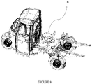
- a typical cargo vehicle driven by an internal combustion engine has a cabin 10 in the operative front side and a cargo section 20 in the operative rear side.
- the cabin 10 has a body predominantly of sheet metal. Typically, the cabin 10 is made of a front dome 11, a roof 12, an operative left door, an operative right door, a floor panel 14 and a back panel 15. The passenger seat is flush with back panel 15.
- a steerable front wheel 16 is positioned in the central and front portion below the front dome 11 and is mechanically linked to a steering handle. The front wheel 16 has a front mud guard 17.
- the cargo section 20 has a chassis 21 comprising two long members 22a, 22b coupled to the cabin 10 and arranged along the longitudinal direction. Cross members span the long members 22a, 22b.
- a sheet metal cargo tray 24 is supported on the chassis 21.
- a left wall, a right wall and a tailgate are attached to a bed of the carrier.
- the chassis 21 supports a prime mover.
- a left rear wheel 27a and a right rear wheel 27b are configured to receive power generated by the prime mover.
- the engine and the fuel tank are disposed below the driver seat.
- the engine and the fuel tank are supported on the chassis 21 of the cargo section 20 below the cargo tray 24, typically by an engine support and suspension frame member 25 that is provided along the central longitudinal axis of the vehicle on a plane below the plane of the long members 22a, 22b.
- the overall weight of the cabin 10, the cargo section 20, the fuel tank and the powertrain is thus supported by the wheels of the vehicle.
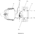
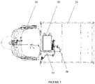
- the present disclosure envisages a battery pack mounting arrangement for a cargo electric vehicle, which is described below with the help of Figures 1-15D .
- the present disclosure envisages a battery pack mounting arrangement for a cargo electrical vehicle.
- the vehicle is defined by a cabin 10 and a cargo section 20 operatively behind the cabin 10.
- the cargo section 20 is supported on a chassis 21 defined by a pair of long members 22a, 22b spaced apart from each other and cross members spanning the long members 22a, 22b transversely.
- the cargo section 20 is defined by a cargo tray 24.
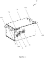
- the mounting arrangement comprises a battery case 31, a first set of brackets 61, a second set of brackets 62 and a set of fasteners 64.
- the battery pack 30, configured to electrochemically store energy and provide, as per the demand, driving power to a powertrain (not shown), is supported on the chassis of the cargo section of the vehicle.
- the case of the battery pack 30 is a rectangular parallelepiped.
- the battery pack 30 is provided with a plurality of connectors including a charging connector 32, a power connector 33 and a communication connector 34.
- the connectors are coupled to the control circuit of the battery pack disposed within the battery case 31 via cables of suitable gauges.
- the portion of the cables where the cables emanate from the battery case 31 is protected by a cable protection clamp 35 fixed on the battery case 31.
- the charging connector 32, connected to the battery pack 30 through a first harness 37, is preferably disposed at the operative left end of the vehicle.
- a second harness 38 connects the battery pack 30 to an e-box (not shown).
- a third harness (not shown) connects the e-box to the powertrain of the vehicle.
- the e-box is an electronic control device that combines the function of a battery management system and a battery junction box.
- the powertrain includes the prime mover that is an electric motor and may include reduction gears.
- the battery pack 30 is mounted to have the connectors 33, 34, 35 on the operative rear side thereof.
- the battery pack 30 is supported on the long members 22a, 22b. Specifically, the battery pack 30 is supported on the long members through four bracket assemblies, wherein two of the bracket assemblies are disposed between the battery pack 30 and the left long member and the other two bracket assemblies are disposed between the battery pack 30 and the right long member.
- the battery case 31 houses the battery pack 30 and is configured to be nested in the cargo section 20 in a space 30a defined by the space between the long members 22a, 22b, a wall of the cabin 10 and a first cross member 23.
- the first set of brackets 61 is weldable to the outer surface of the opposite walls of the battery case 31 in a predetermined spaced apart distance (d).
- the second set of brackets 62 is weldable to the long members and is spaced apart with respect to each other at a distance (D), and is complementary to the first set of brackets 61 in the operative configuration of the arrangement.
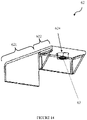
- Tongues 612, 622 extend from the first set of brackets 61 and the second set of brackets 62.
- a first set of apertures 614 is provided on the tongues 612 in the first set of brackets 61.
- a second set of apertures 624 is provided on the tongues 622 in the second set of brackets 62.
- the first set of apertures 614 and the second set of apertures 624 are configured to be aligned to each other along common axes when the first set of tongues 612 is supported on the second set of tongues 622 in an operative configuration of the arrangement.
- the set of fasteners 64 is configured to fasten the first set of brackets 61 to the second set of brackets 62 via the first set of apertures 614 and the second set of apertures 624 for mounting the battery pack 30 in a nested configuration in the cargo section in the space 30a.
- a nut 63 is fixed by welding, on the operative lower surface of the first tongue 612.
- the nut 63 is aligned with the first aperture 614 for receiving the fastener 64.
- the second set of brackets 62 is fixed on the surface of the battery case 31 of the battery pack 30 with the shortest width.
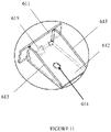
- each of the first brackets 61 is L-shaped, has a case-side wall 611 weldable to the battery case 31 and is provided with reinforcing ribs 613.
- the first tongue 612 of the first bracket 61 extends from the case-side wall 611 towards an operatively outer side of the battery case 31.
- the first bracket 61 is a sheet metal component.
- the case-side wall 611 and the first tongue 612 are at a 90° inclination to one another.
- the case-side wall 611 is fixed on the battery case 31 of the battery pack 30 and the first tongue 612 extends perpendicular to the surface of the battery case 31 of the battery pack 30 and parallel to the operative horizontal plane of the battery pack 30.
- each of the second brackets 62 has an overlapping portion 621 weldable to a long member and is shaped to overlap an operative top surface of the long member.
- the second tongue 622 of the second bracket 62 extends from the overlapping portion 621 towards an operatively inner side of the corresponding long member relative to the vehicle.
- the battery pack mounting arrangement comprises four first brackets 61 and four second brackets 62.
- the battery pack 30 is disposed at an operative front extreme position between the long members 22a, 22b.
- the battery pack 30 is disposed below the cargo tray 24. In an embodiment, the battery pack 30 is disposed below the bed of the cargo tray 24.
- each of the long members 22a, 22b has a box-type construction and majority of the area of the lateral surfaces of the battery pack 30 is covered by the lateral surfaces of the long members 22a, 22b on either side.
- the centre of gravity of the battery pack 30 lies within a space between the lateral surfaces of the long members 22a, 22b.
- the battery pack 30 is disposed to have the longest dimension of the battery pack 30 extend in a lateral axis of the vehicle.
- the battery case 31 has a rectangular cross-section.
- the first set of brackets 61 are spaced apart from corners of the battery case 31.
- the ratio of the centre distance between the apertures 614 to the width of the battery case 31 ranges between 0.6 and 0.95.
- each of the first brackets 61 is folded from a single first blank 616. Thickness of the first blank 616 ranges between 2mm and 4mm.
- each of the second brackets 62 is folded from a single second blank 626. Thickness of the second blank 626 ranges between 2mm and 4 mm.
- Centre of the first aperture 614 is 41.7 mm away from the lateral edge of the first tongue 612, and the ratio of the diameter of the first aperture 614 to the distance of the centre of the first aperture 614 from the lateral edge of the first tongue 612 is ranges between 0.1 and 0.5.
- centre of the second aperture 624 is 17 mm away from the lateral edge of the second tongue 622, and the ratio of the diameter of the second aperture 624 to the distance of the centre of the second aperture 624 from the lateral edge of the second tongue 622 ranges between 0.15 and 1.
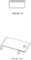
- the preferred method of manufacturing of the first bracket 61 starts with a first blank 616 of sheet metal that has a shape as shown in Figure 12A .
- the first blank 616 has a first fold line 617, a second fold line 618 and a third fold line 619.
- the first fold line 617 separates the case-side wall 611 and the first tongue 612 to be formed.
- the second fold line 618 and the third fold line 619 define the ribs 613.
- a First aperture 614 is pierced in the area that defines the first tongue before the first blank 616 is folded at the fold lines 617, 618, 619. Each of the folds is through 90° on the same side of the blank.
- the first bracket 61 is fixed on the battery case 31 of the battery pack 30 by welding between the peripheral edges of the case-side wall 611 and the surface of the battery case 31.
- the preferred method of manufacturing of the second bracket 62 starts with a second blank 626 of sheet metal that is rectangular in shape.
- the second blank 626 is folded to obtain the overlapping portion 621 and the second tongue 622.
- the second blank 626 is folded at three positions along its longitudinal extent, wherein a first bend 626a is through 90° on a first side, a second bend 626b is through 180° on a first side and a third bend 626c is through 90° on a second side.
- edge defined by the third bend 627 lies close to and along an operative lower surface of the second bracket 62 thus obtained.
- Fillet welding is performed along the edge defined by the third bend 627 to fix the edge defined by the third bend 627 to the operative inner surface of the second bracket 62.
- a second aperture 624 is pierced and a nut 63 is fixed by welding, on the operative lower surface of the second tongue 622, wherein the nut 63 is aligned with the second aperture 624.
- the second bracket 62 is fixed on the corresponding long member by performing a fillet-weld between the operative vertical edges of the overlapping portion 621 and the surface of the corresponding long member.
- the present disclosure envisages a cargo electrical vehicle comprising a cabin (10), a cargo section (20) arranged behind the cabin (10) and defined by a cargo tray (24), a battery pack (30) and a battery pack mounting arrangement.
- the cargo section (20) is supported on a chassis (21) of the vehicle defined by a pair of long members (22a, 22b) spaced apart from each other and cross members spanning the long members (22a, 22b).
- the cargo electric vehicle is a three-wheeled cargo electric vehicle.
- the present disclosure further envisages a method of mounting a battery pack 30 in a cargo electrical vehicle defined by a cabin 10, a cargo section 20 operatively behind the cabin 10.
- the cargo section 20 is supported on a chassis 21 defined by a pair of long members 22a, 22b spaced apart from each other and cross members spanning the long members 22a, 22b transversely.
- the cargo section 20 is defined by a cargo tray 24.
- the method comprises the steps of:
- the mounting of the battery pack 30 is performed by lowering the battery pack 30 between the long members 22a, 22b of the vehicle while the first brackets 61 are aligned with the corresponding second brackets 62.
- the lowering of the battery pack 30 is preferably done using external power to control the lowering speed and thereby prevent an impact and of the brackets and subsequent misalignment or deformation.
- Lowering hooks 36 are provided on the battery case 31 of the battery pack 30 to facilitate lifting and lowering of the battery pack 30.
- the Second aperture on the first bracket is aligned with the First aperture on the corresponding second bracket.
- a fastener 64 is screwed through the aligned apertures.
- the battery pack 30 is rigidly mounted on the long members 22a, 22b.
- the fasteners are unscrewed and the battery pack 30 is lifted by holding at the hooks 36.
- the battery pack mounting arrangement of the present disclosure ensures that the battery pack 30 is located safely away from the cabin of the vehicle, thereby protecting the driver from any fire hazard related to the battery pack 30.
- the position of the battery pack being optimally close to the centre of gravity of the vehicle in its unloaded state, ride and handling characteristics are not affected due to the significant ratio of the weight of the battery pack to the vehicle's kerb weight.
- the battery pack is particularly placed at an optimally low position so that the overall centre of gravity of the vehicle is at a significantly low position, as a result of which stability at cornering is enhanced.
- the present disclosure described herein above has several technical advantages including, but not limited to, the realization of a battery pack mounting arrangement for a cargo electric vehicle, that ensures:
Landscapes
- Engineering & Computer Science (AREA)
- Chemical & Material Sciences (AREA)
- Combustion & Propulsion (AREA)
- Transportation (AREA)
- Mechanical Engineering (AREA)
- Battery Mounting, Suspending (AREA)
Applications Claiming Priority (1)
| Application Number | Priority Date | Filing Date | Title |
|---|---|---|---|
| IN202021050433 | 2020-11-19 |
Publications (1)
| Publication Number | Publication Date |
|---|---|
| EP4000978A1 true EP4000978A1 (fr) | 2022-05-25 |
Family
ID=78413819
Family Applications (1)
| Application Number | Title | Priority Date | Filing Date |
|---|---|---|---|
| EP21205029.8A Pending EP4000978A1 (fr) | 2020-11-19 | 2021-10-27 | Agencement de montage de bloc-batterie pour un véhicule électrique de chargement |
Country Status (1)
| Country | Link |
|---|---|
| EP (1) | EP4000978A1 (fr) |
Cited By (3)
| Publication number | Priority date | Publication date | Assignee | Title |
|---|---|---|---|---|
| CN120261897A (zh) * | 2025-05-30 | 2025-07-04 | 宁德时代新能源科技股份有限公司 | 电池装置、用电装置及储能装置 |
| WO2025177288A1 (fr) * | 2024-02-21 | 2025-08-28 | Tvs Motor Company Limited | Ensemble de montage pour au moins une unité de batterie d'un véhicule |
| WO2026003848A1 (fr) * | 2024-06-27 | 2026-01-02 | Tvs Motor Company Limited | Ensemble de montage pour une ou plusieurs unités de stockage d'énergie d'un véhicule à roues multiples |
Citations (3)
| Publication number | Priority date | Publication date | Assignee | Title |
|---|---|---|---|---|
| US20090152034A1 (en) * | 2007-12-14 | 2009-06-18 | Seiichi Takasaki | Battery unit mounting structure for electric vehicle |
| WO2016149836A1 (fr) * | 2015-03-26 | 2016-09-29 | Services Automobiles Grantuned Inc. | Kit de conversion d'un mode de carburant à un mode électrique réutilisable et procédé de conversion et de réutilisation du kit de conversion |
| WO2020003835A1 (fr) * | 2018-06-27 | 2020-01-02 | ダイムラー・アクチェンゲゼルシャフト | Dispositif de support de bloc-batterie de véhicule |
-
2021
- 2021-10-27 EP EP21205029.8A patent/EP4000978A1/fr active Pending
Patent Citations (3)
| Publication number | Priority date | Publication date | Assignee | Title |
|---|---|---|---|---|
| US20090152034A1 (en) * | 2007-12-14 | 2009-06-18 | Seiichi Takasaki | Battery unit mounting structure for electric vehicle |
| WO2016149836A1 (fr) * | 2015-03-26 | 2016-09-29 | Services Automobiles Grantuned Inc. | Kit de conversion d'un mode de carburant à un mode électrique réutilisable et procédé de conversion et de réutilisation du kit de conversion |
| WO2020003835A1 (fr) * | 2018-06-27 | 2020-01-02 | ダイムラー・アクチェンゲゼルシャフト | Dispositif de support de bloc-batterie de véhicule |
Cited By (3)
| Publication number | Priority date | Publication date | Assignee | Title |
|---|---|---|---|---|
| WO2025177288A1 (fr) * | 2024-02-21 | 2025-08-28 | Tvs Motor Company Limited | Ensemble de montage pour au moins une unité de batterie d'un véhicule |
| WO2026003848A1 (fr) * | 2024-06-27 | 2026-01-02 | Tvs Motor Company Limited | Ensemble de montage pour une ou plusieurs unités de stockage d'énergie d'un véhicule à roues multiples |
| CN120261897A (zh) * | 2025-05-30 | 2025-07-04 | 宁德时代新能源科技股份有限公司 | 电池装置、用电装置及储能装置 |
Similar Documents
| Publication | Publication Date | Title |
|---|---|---|
| EP4000978A1 (fr) | Agencement de montage de bloc-batterie pour un véhicule électrique de chargement | |
| US12403794B2 (en) | Electric vehicle battery unit and battery unit installation method | |
| US7717207B2 (en) | Mounting structure for storage battery device | |
| US9409495B2 (en) | Vehicle apparatus attaching structure | |
| US20060289224A1 (en) | Vehicle body structure | |
| EP3293087A1 (fr) | Élément transversal dans le sol avec géométrie spéciale pour monter le bloc-batterie | |
| US20080149410A1 (en) | Arrangement structure of component parts for fuel cell vehicle | |
| CN103253120B (zh) | 车辆后部结构 | |
| EP3293078A1 (fr) | Raccord pour l'élément transversal et le seuil (ponton) | |
| JP2020044992A (ja) | 車両 | |
| US10414442B2 (en) | Trunk as stiffening element | |
| US11845346B2 (en) | Carrier assembly for multiple fuel cells | |
| JP2007203912A (ja) | 車体後部構造 | |
| US12545129B2 (en) | Fuel cell vehicle | |
| US11541943B2 (en) | Electric vehicle having low-voltage component in rear portion of vehicle body | |
| US10549620B2 (en) | Profiles in the floor section | |
| EP3293077A1 (fr) | Paroi avant | |
| US20190351786A1 (en) | Seat rail | |
| US7185724B2 (en) | Battery support structure | |
| US10661832B2 (en) | Angle and geometry of the front cross member | |
| JP2003127907A (ja) | 自動車の後部車体構造 | |
| US20180065578A1 (en) | Profile of the front cross member | |
| CN220009957U (zh) | 一种无人车底盘结构及无人车 | |
| US20240227575A1 (en) | Vehicle | |
| CN119348713B (zh) | 一种后碰撞安全性高的车身后舱结构及车辆 |
Legal Events
| Date | Code | Title | Description |
|---|---|---|---|
| PUAI | Public reference made under article 153(3) epc to a published international application that has entered the european phase |
Free format text: ORIGINAL CODE: 0009012 |
|
| STAA | Information on the status of an ep patent application or granted ep patent |
Free format text: STATUS: THE APPLICATION HAS BEEN PUBLISHED |
|
| AK | Designated contracting states |
Kind code of ref document: A1 Designated state(s): AL AT BE BG CH CY CZ DE DK EE ES FI FR GB GR HR HU IE IS IT LI LT LU LV MC MK MT NL NO PL PT RO RS SE SI SK SM TR |
|
| STAA | Information on the status of an ep patent application or granted ep patent |
Free format text: STATUS: REQUEST FOR EXAMINATION WAS MADE |
|
| 17P | Request for examination filed |
Effective date: 20221025 |
|
| RBV | Designated contracting states (corrected) |
Designated state(s): AL AT BE BG CH CY CZ DE DK EE ES FI FR GB GR HR HU IE IS IT LI LT LU LV MC MK MT NL NO PL PT RO RS SE SI SK SM TR |
|
| STAA | Information on the status of an ep patent application or granted ep patent |
Free format text: STATUS: EXAMINATION IS IN PROGRESS |
|
| 17Q | First examination report despatched |
Effective date: 20250131 |