EP4001011B1 - Système de commande de véhicule - Google Patents
Système de commande de véhicule Download PDFInfo
- Publication number
- EP4001011B1 EP4001011B1 EP20848129.1A EP20848129A EP4001011B1 EP 4001011 B1 EP4001011 B1 EP 4001011B1 EP 20848129 A EP20848129 A EP 20848129A EP 4001011 B1 EP4001011 B1 EP 4001011B1
- Authority
- EP
- European Patent Office
- Prior art keywords
- zone
- ecu
- zone ecu
- central processing
- signal
- Prior art date
- Legal status (The legal status is an assumption and is not a legal conclusion. Google has not performed a legal analysis and makes no representation as to the accuracy of the status listed.)
- Active
Links
Images



Classifications
-
- B—PERFORMING OPERATIONS; TRANSPORTING
- B60—VEHICLES IN GENERAL
- B60Q—ARRANGEMENT OF SIGNALLING OR LIGHTING DEVICES, THE MOUNTING OR SUPPORTING THEREOF OR CIRCUITS THEREFOR, FOR VEHICLES IN GENERAL
- B60Q1/00—Arrangement of optical signalling or lighting devices, the mounting or supporting thereof or circuits therefor
- B60Q1/26—Arrangement of optical signalling or lighting devices, the mounting or supporting thereof or circuits therefor the devices being primarily intended to indicate the vehicle, or parts thereof, or to give signals, to other traffic
- B60Q1/34—Arrangement of optical signalling or lighting devices, the mounting or supporting thereof or circuits therefor the devices being primarily intended to indicate the vehicle, or parts thereof, or to give signals, to other traffic for indicating change of drive direction
-
- H—ELECTRICITY
- H04—ELECTRIC COMMUNICATION TECHNIQUE
- H04L—TRANSMISSION OF DIGITAL INFORMATION, e.g. TELEGRAPHIC COMMUNICATION
- H04L12/00—Data switching networks
- H04L12/28—Data switching networks characterised by path configuration, e.g. LAN [Local Area Networks] or WAN [Wide Area Networks]
- H04L12/2803—Home automation networks
- H04L12/2807—Exchanging configuration information on appliance services in a home automation network
-
- B—PERFORMING OPERATIONS; TRANSPORTING
- B60—VEHICLES IN GENERAL
- B60R—VEHICLES, VEHICLE FITTINGS, OR VEHICLE PARTS, NOT OTHERWISE PROVIDED FOR
- B60R16/00—Electric or fluid circuits specially adapted for vehicles and not otherwise provided for; Arrangement of elements of electric or fluid circuits specially adapted for vehicles and not otherwise provided for
- B60R16/02—Electric or fluid circuits specially adapted for vehicles and not otherwise provided for; Arrangement of elements of electric or fluid circuits specially adapted for vehicles and not otherwise provided for electric constitutive elements
- B60R16/023—Electric or fluid circuits specially adapted for vehicles and not otherwise provided for; Arrangement of elements of electric or fluid circuits specially adapted for vehicles and not otherwise provided for electric constitutive elements for transmission of signals between vehicle parts or subsystems
-
- B—PERFORMING OPERATIONS; TRANSPORTING
- B60—VEHICLES IN GENERAL
- B60Q—ARRANGEMENT OF SIGNALLING OR LIGHTING DEVICES, THE MOUNTING OR SUPPORTING THEREOF OR CIRCUITS THEREFOR, FOR VEHICLES IN GENERAL
- B60Q1/00—Arrangement of optical signalling or lighting devices, the mounting or supporting thereof or circuits therefor
- B60Q1/26—Arrangement of optical signalling or lighting devices, the mounting or supporting thereof or circuits therefor the devices being primarily intended to indicate the vehicle, or parts thereof, or to give signals, to other traffic
- B60Q1/34—Arrangement of optical signalling or lighting devices, the mounting or supporting thereof or circuits therefor the devices being primarily intended to indicate the vehicle, or parts thereof, or to give signals, to other traffic for indicating change of drive direction
- B60Q1/38—Arrangement of optical signalling or lighting devices, the mounting or supporting thereof or circuits therefor the devices being primarily intended to indicate the vehicle, or parts thereof, or to give signals, to other traffic for indicating change of drive direction using immovably-mounted light sources, e.g. fixed flashing lamps
-
- G—PHYSICS
- G06—COMPUTING OR CALCULATING; COUNTING
- G06F—ELECTRIC DIGITAL DATA PROCESSING
- G06F1/00—Details not covered by groups G06F3/00 - G06F13/00 and G06F21/00
- G06F1/04—Generating or distributing clock signals or signals derived directly therefrom
- G06F1/14—Time supervision arrangements, e.g. real time clock
-
- H—ELECTRICITY
- H04—ELECTRIC COMMUNICATION TECHNIQUE
- H04L—TRANSMISSION OF DIGITAL INFORMATION, e.g. TELEGRAPHIC COMMUNICATION
- H04L12/00—Data switching networks
- H04L12/28—Data switching networks characterised by path configuration, e.g. LAN [Local Area Networks] or WAN [Wide Area Networks]
-
- H—ELECTRICITY
- H04—ELECTRIC COMMUNICATION TECHNIQUE
- H04L—TRANSMISSION OF DIGITAL INFORMATION, e.g. TELEGRAPHIC COMMUNICATION
- H04L12/00—Data switching networks
- H04L12/28—Data switching networks characterised by path configuration, e.g. LAN [Local Area Networks] or WAN [Wide Area Networks]
- H04L12/40—Bus networks
- H04L2012/40208—Bus networks characterized by the use of a particular bus standard
- H04L2012/40215—Controller Area Network CAN
-
- H—ELECTRICITY
- H04—ELECTRIC COMMUNICATION TECHNIQUE
- H04L—TRANSMISSION OF DIGITAL INFORMATION, e.g. TELEGRAPHIC COMMUNICATION
- H04L12/00—Data switching networks
- H04L12/28—Data switching networks characterised by path configuration, e.g. LAN [Local Area Networks] or WAN [Wide Area Networks]
- H04L12/40—Bus networks
- H04L2012/40267—Bus for use in transportation systems
- H04L2012/40273—Bus for use in transportation systems the transportation system being a vehicle
-
- Y—GENERAL TAGGING OF NEW TECHNOLOGICAL DEVELOPMENTS; GENERAL TAGGING OF CROSS-SECTIONAL TECHNOLOGIES SPANNING OVER SEVERAL SECTIONS OF THE IPC; TECHNICAL SUBJECTS COVERED BY FORMER USPC CROSS-REFERENCE ART COLLECTIONS [XRACs] AND DIGESTS
- Y02—TECHNOLOGIES OR APPLICATIONS FOR MITIGATION OR ADAPTATION AGAINST CLIMATE CHANGE
- Y02B—CLIMATE CHANGE MITIGATION TECHNOLOGIES RELATED TO BUILDINGS, e.g. HOUSING, HOUSE APPLIANCES OR RELATED END-USER APPLICATIONS
- Y02B20/00—Energy efficient lighting technologies, e.g. halogen lamps or gas discharge lamps
- Y02B20/40—Control techniques providing energy savings, e.g. smart controller or presence detection
Definitions
- the technology disclosed herein relates to a vehicle control system.
- Patent Literature 1 discloses a technique in which a plurality of domains divided on the basis of the function of an in-vehicle device are provided, a domain control unit is provided for each domain, and a plurality of the domain control units are controlled by an integrated control unit.
- each device control unit is implemented by a single or a plurality of ECUs, and these ECUs are connected by a hierarchical network.
- Patent Literature 2 discloses a technique of providing a gateway or a network hub (HUB) that relays data transmission and reception between nodes in different networks in an in-vehicle network system.
- UOB network hub
- US 9 756 590 B2 discloses a vehicle system structure comprises a central gateway for protocol/message conversion between different bus systems. Different nodes are connected to the bus systems each having a control unit for controlling a connected actuator and an internal clock. The clocks are synchronized by the gateway so that the each node can determine the precise time at which a message has been generated and sent by a first node based on a timestamp included in the message header.
- vehicle interior and exterior environment information including information about a driver's operation
- sensor a sensor, or the like
- arithmetic processing is performed on the basis of the acquired vehicle interior and exterior environment information
- various actuators mounted on the vehicle are controlled on the basis of the arithmetic result.
- the arithmetic processing function and the control function of each actuator will be integrated into a central processing unit that integrally manages the operation of the entire vehicle.
- the technology disclosed herein has been made in view of such a point, and an object thereof is to enable synchronous control of actuators distributed in a vehicle even in a case where the control function of the actuator is incorporated in a central processing unit.
- the technology disclosed herein relates to a vehicle control system according to the features of claim 1.
- actuators distributed in the vehicle can be synchronously controlled even in a case where the control function of the actuator is incorporated in the central processing unit.
- the output function of the actuator control signal is incorporated in the central processing unit, timing adjustment is handled on a zone ECU side.
- the first actuator and second actuator can be blinkers.
- each of the first zone ECUs can be configured in a manner that in a case where the blinking timing of another first zone ECU is earlier than the blinking timing of the first zone ECUs, a turn-off start time during a blinking period is made to match a turn-off time of another first zone ECU.
- actuators distributed in the vehicle can be synchronously controlled even in a case where the control function of the actuator is incorporated in the central processing unit.
- in-vehicle devices devices that execute traveling control, such as sensors and actuators mounted on a vehicle, are referred to as “in-vehicle devices” or simply “devices”.
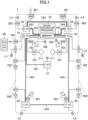
- Fig. 1 is a diagram illustrating a configuration example of an in-vehicle network system.
- the in-vehicle network system illustrated in Fig. 1 is mounted on a vehicle 1 and includes a plurality of zone ECUs 2 each of which is disposed in each predetermined zone of the vehicle and a central processing unit 10 that integrally controls the zone ECUs 2.
- a central processing unit 10 that integrally controls the zone ECUs 2.
- the vehicle 1 is divided into seven zones and each zone includes the zone ECU 2.
- the central processing unit 10 is an example of a central ECU.
- each zone ECU 2 functions as a network hub device having a function to relay information transmitted via a network.
- the zone ECU 2 disposed in the left dash zone near the left front seat of the vehicle 1 is referred to as "first zone ECU 21”
- the zone ECU 2 disposed in the right dash zone near the right front seat of the vehicle 1 is referred to as "second zone ECU 22" in some cases.
- the zone ECU 2 disposed in the left front zone on the left front side of the vehicle 1 is referred to as "third zone ECU 23”
- the zone ECU 2 disposed in the right front zone on the right front side of the vehicle 1 is referred to as "fourth zone ECU 24" in some cases.
- the zone ECU 2 disposed in the left rear zone on the left rear side of the vehicle 1 is referred to as "fifth zone ECU 25", and the zone ECU 2 disposed in the right rear zone on the right rear side of the vehicle 1 is referred to as "sixth zone ECU 26" in some cases.
- the zone ECU 2 disposed in the console zone near the center console of the vehicle 1 is referred to as "seventh zone ECU 27".
- the hub devices 21 to 27 are not distinguished, they are simply referred to as "zone ECU 2".
- the number of zones is increased or decreased, the number of zone ECUs 2 is also increased or decreased accordingly.
- the zone ECU 2 is configured to be able to connect in-vehicle devices such as a smart ECU, a smart actuator, a sensor, and/or an actuator, which will be described later.
- in-vehicle devices such as a smart ECU, a smart actuator, a sensor, and/or an actuator, which will be described later.
- the present embodiment shows an example in which the zone ECU 2 is provided in each zone, but the present invention is not limited thereto, and for example, the zone ECU for connecting an in-vehicle device corresponding to a specific function can be provided regardless of the zone.
- the zone can include a plurality of zone ECUs.
- the smart ECU can also function as the zone ECU, or the zone ECU can also function as the smart ECU.
- the first zone ECU 21, the second zone ECU 22, the third zone ECU 23, and the fourth zone ECU 24 have a function as an Ethernet hub device (denoted as "E-EC" in Fig. 1 ) that transmits and receives Ethernet (registered trademark) signals to and from the central processing unit 10.
- E-EC Ethernet hub device
- the central processing unit 10 and the first zone ECU 21 are connected by an Ethernet cable EB1
- the central processing unit 10 and the second zone ECU 22 are connected by an Ethernet cable EB2.
- the central processing unit 10 and the third zone ECU 23 are connected by an Ethernet cable EB3
- the central processing unit 10 and the fourth zone ECU 24 are connected by an Ethernet cable EB4.
- the Ethernet protocol has a mechanism (Time Sensitive Networking (TSN)) for compensating for communication synchronization.
- TSN Time Sensitive Networking
- the Ethernet protocol is an example of a time synchronization network. That is, in the example of Fig. 1 , the central processing unit 10, the first zone ECU 21, the second zone ECU 22, the third zone ECU 23, and the fourth zone ECU 24 are connected by the time synchronization network.
- the first to fourth zone ECUs 21 to 24 are examples of a first zone ECU or a second zone ECU in the present disclosure.
- the Ethernet signal is a signal conforming to the Ethernet protocol.
- the CAN signal to be described later is a signal conforming to the CAN protocol
- the CAN-FD signal is a signal conforming to the CAN-FD protocol
- the local interconnect network (LIN) signal is a signal conforming to the LIN protocol.
- the fifth zone ECU 25, the sixth zone ECU 26, and the seventh zone ECU 27 function as a CAN hub device (denoted as "C-EC" in Fig. 1 ) that transmits and receives a CAN with Flexible Data-Rate (CAN-FD) signal or a CAN (Controller Area Network) signal to and from the central processing unit 10 and/or another zone ECU 2.
- CAN-FD CAN with Flexible Data-Rate
- CAN-FD Controller Area Network
- the first zone ECU 21 and the fifth zone ECU 25 are connected by a CAN-FD cable CB5
- the second zone ECU 22 and the sixth zone ECU 26 are connected by a CAN-FD cable CB6
- the fifth zone ECU 25 and the sixth zone ECU 26 are connected by a CAN-FD cable CB8.
- the first zone ECU 21 and the seventh zone ECU 27 are connected by a CAN-FD cable CB7.
- the CAN protocol, the CAN-FD protocol, and the LIN protocol are examples of time
- the network formed by signal transmission paths between the central processing unit 10 and the zone ECUs 2 and signal transmission paths between the zone ECUs 2 is referred to as "trunk network".
- the trunk network includes the Ethernet cables EB1 to EB5 and the CAN-FD cables CB5 to CB8.
- the transmission path of the Ethernet signal (a signal conforming to the Ethernet standard) is indicated by a thick solid line
- the transmission path of the CAN-FD signal or the CAN signal is indicated by a middle thick solid line.
- the signal transmission path from each of the zone ECUs 21 to 27 to the in-vehicle device side is referred to as "device-side network”.
- device-side network the signal transmission path from each of the zone ECUs 21 to 27 to the in-vehicle device side
- the signal path from each of the zone ECUs 21 to 27 to each in-vehicle device, that is, the device-side network is indicated by a thin solid line.
- the signal paths indicated by thin solid lines include analog/digital signal paths, CAN signal paths, LIN signal paths, and CAN-FD signal paths.
- the central processing unit 10 calculates a route on which the vehicle 1 should travel in response to outputs from sensors mounted on the vehicle 1, and determines the motion of the vehicle 1 for following the route.
- the central processing unit 10 is, for example, a processor including one or a plurality of chips, and has an artificial intelligence (AI) function in some cases.
- AI artificial intelligence
- the central processing unit 10 includes a processor and a memory.
- the memory stores a module that is software executable by the processor.
- Each function of the central processing unit 10 is implemented, for example, by the processor executing a module corresponding to each function. Note that the processor and the memory can be provided in plural.
- the sensors that output information to the central processing unit 10 include, for example, a camera that captures an environment outside the vehicle, a radar that detects a target or the like outside the vehicle, a global positioning system (GPS) sensor that detects a position of the vehicle 1, a vehicle state sensor that detects a behavior of the vehicle such as a vehicle speed, an acceleration, and a yaw rate, and an occupant state sensor that acquires a state of an occupant of the vehicle such as an in-vehicle camera.
- GPS global positioning system
- communication information from other vehicles located around an own vehicle and/or traffic information from a navigation system can be input to the central processing unit 10.
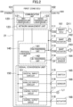
- Fig. 2 is a diagram illustrating a functional configuration example of the first zone ECU 21.
- the first zone ECU 21 includes a communication unit 120, a protocol conversion unit 140, and a signal conversion unit 150.
- the protocol conversion unit 140 includes a CAN conversion unit 141 and a LIN conversion unit 142.
- the signal conversion unit 150 includes a digital input circuit 151, an analog input circuit 152, and control output circuits 153 and 154.
- the first zone ECU 21 includes, as communication ports (hereinafter, referred to as "trunk ports") connected to the trunk network, a trunk port 101 to which the Ethernet cable EB1 is connected and a trunk port 102 to which the CAN-FD cable CB5 is connected.
- the trunk port 101 and the trunk port 102 are ports to which a trunk network signal that is a signal transmitted on the trunk network is input and output.
- the first zone ECU 21 includes communication ports 111 to 118 as communication ports connected to the device-side network.
- the first zone ECU 21 inputs and outputs CAN signals via the communication ports 111 to 113, inputs and outputs LIN signals via the communication port 114, inputs digital control signals via the communication port 115, inputs analog control signals via the communication port 116, and outputs analog control signals via the communication ports 117 and 118.
- the communication port 111 is connected to a smart ECU 161
- the smart ECU 161 is connected to an airbag device D11.
- the communication port 112 is connected to a smart actuator 162 for locking and unlocking a side door.
- the communication port 113 is connected to a smart actuator 163 for emitting a buzzer sound or the like.
- the communication port 114 is connected to a sensor 164 (hereinafter, referred to as "keyless sensor 164") for operating a keyless device.
- the communication port 115 is connected to a switch 165 (for example, a clutch cut switch, a brake switch, or the like).
- the communication port 116 is connected to a sensor 166 (for example, an accelerator pedal sensor, a clutch stroke sensor, or the like).
- the communication port 117 is connected to a left-side turn light L1 provided on a door mirror on the left side of the vehicle.
- the communication port 118 is connected to an actuator 168 (for example, an indicator lamp or the like attached to a horn, a keyless buzzer, a meter device, or the like).
- an actuator 168 for example, an indicator lamp or the like attached to a horn, a keyless buzzer, a meter device, or the like.
- the symbol mark of a lock mechanism is illustrated in addition to the smart actuator 162 for easy understanding of the description.
- the symbol mark of a sound source mechanism is illustrated.
- the in-vehicle device can be attached or detached by inserting a connector at the distal end of a cable extending from the in-vehicle device into each of the communication ports 111 to 118.
- each of the communication ports 111 to 118 can be connected to a smart connector (not illustrated), and the in-vehicle device can be attached to the smart connector.
- the smart connector SC includes, for example, an analog/digital conversion circuit, a driver circuit, and the like, and has a function of transmitting a drive signal to an actuator serving as the in-vehicle device, and/or a function of transmitting an input signal from a sensor serving as the in-vehicle device to the zone ECU 2.
- the communication unit 120 includes a first transmission and reception unit 121 connected to the trunk port 101, a second transmission and reception unit 122 connected to the trunk port 102, and a network management unit 123.
- the first transmission and reception unit 121 has a function of transmitting and receiving a trunk network signal (an Ethernet signal) to and from the central processing unit 10 via the trunk port 101 and the Ethernet cable EB1.
- a trunk network signal an Ethernet signal
- the first transmission and reception unit 121 includes, for example, a coding circuit that generates an Ethernet signal, a driver circuit that outputs the Ethernet signal generated by the coding circuit to the central processing unit 10, a receiver circuit that receives the Ethernet signal output from the central processing unit 10, and a decoding circuit that decodes the Ethernet signal received by the receiver circuit.
- the second transmission and reception unit 122 has a function of transmitting and receiving a trunk network signal (a CAN-FD signal) to and from the fifth zone ECU 25 via the trunk port 102 and the CAN-FD cable CB5.
- the second transmission and reception unit 122 includes, for example, a coding circuit that generates a CAN-FD signal, a driver circuit that outputs the CAN-FD signal generated by the coding circuit to the fifth zone ECU 25, a receiver circuit that receives the CAN-FD signal output from the fifth zone ECU 25, and a decoding circuit that decodes the CAN-FD signal received by the receiver circuit.
- the network management unit 123 has (a) a relay function of relaying a trunk network signal on a trunk network, that is, between the trunk ports 101 and 102, (b) a distribution function of extracting a signal for a device connected to the own ECU from trunk network signals and distributing the signal, and (c) an integration function of integrating data to be transmitted from the device connected to the own ECU to the central processing unit 10 and/or another zone ECU 2.
- a relay function of relaying a trunk network signal on a trunk network, that is, between the trunk ports 101 and 102
- a distribution function of extracting a signal for a device connected to the own ECU from trunk network signals and distributing the signal
- an integration function of integrating data to be transmitted from the device connected to the own ECU to the central processing unit 10 and/or another zone ECU 2.
- the protocol conversion unit 140 performs protocol conversion so that data can be exchanged between communication schemes. Specifically, the protocol conversion unit 140 is connected to the network management unit 123, and performs protocol conversion according to each of "(a) relay function", “(b) distribution function", and "(c) integration function” of the network management unit 123 described above. Note that, in the present embodiment, the protocol conversion includes a conversion process such as data length conversion between CAN and CAN-FD.
- the network management unit 123 extracts data (hereinafter, referred to as "relay data”) to be transmitted to the fifth zone ECU 25 from the Ethernet signal input from the central processing unit 10, and outputs the extracted data to the protocol conversion unit 140.
- the protocol conversion unit 140 converts relay data to CAN protocol data and outputs the CAN protocol data to the network management unit 123.
- the network management unit 123 generates a CAN signal on the basis of the CAN protocol data.
- the second transmission and reception unit 122 then outputs the CAN signal to the fifth zone ECU 25 via the trunk port 102.
- the network management unit 123 extracts data (hereinafter, referred to as "relay data") to be transmitted to the central processing unit 10 from the CAN signal input from the fifth zone ECU 25, and outputs the extracted data to the protocol conversion unit 140.
- the protocol conversion unit 140 converts the relay data to data in a format conforming to the Ethernet protocol and outputs the data to the network management unit 123.
- the network management unit 123 generates an Ethernet signal on the basis of the converted data.
- the first transmission and reception unit 121 then outputs the Ethernet signal to the central processing unit 10 via the trunk port 101.
- the network management unit 123 extracts data (hereinafter, referred to as "own ECU data") for a device connected to the own ECU from the Ethernet signal input from the central processing unit 10.
- the network management unit 123 determines whether the data for the own ECU is data for a device connected to the protocol conversion unit 140 or data for a device connected to the signal conversion unit 150, and distributes the data to each of the units.
- the protocol conversion unit 140 when data for devices connected to the communication ports 111 to 113 is received from the network management unit 123, the CAN conversion unit 141 converts the received data to a signal conforming to the CAN protocol and outputs the signal to the communication ports 111 to 113.
- a signal for example, a control signal
- the control output circuit 153 when data for controlling the left-side turn light L1 connected to the communication port 117 is received from the network management unit 123, the control output circuit 153 generates, for example, an analog control signal of the left-side turn light L1 according to a control value received from the central processing unit 10, and outputs the analog control signal to the communication port 117.
- the control output circuit 154 when data for controlling the actuator 168 connected to the communication port 118 is received from the network management unit 123, the control output circuit 154 generates, for example, an analog control signal of the actuator 168 according to a control value received from the central processing unit 10, and outputs the analog control signal to the communication port 118. Note that, the process similar to that in the case of the central processing unit 10 described above is also performed in a case where data for a device connected to the own ECU is included in the CAN signal input from the fifth zone ECU 25.
- the protocol conversion unit 140 receives an unlock signal (a LIN signal) from the keyless sensor 164, converts data conforming to the LIN protocol to data conforming to the Ethernet protocol, and transmits the converted data to the network management unit 123.
- the digital input circuit 151 receives an input signal from the switch 165
- the analog input circuit 152 receives an input signal from the sensor 166
- the circuits 151 and 152 transmit the received data to the network management unit 123.
- the network management unit 123 integrates the received data from the protocol conversion unit 140 and the received data from the signal conversion unit 150.
- the first transmission and reception unit 121 outputs the data integrated by the network management unit 123, as an Ethernet signal, to the central processing unit 10 via the trunk port 101. Note that, the process similar to that in the case of outputting the data to the central processing unit 10 is also performed in the case of transmitting the data integrated by the integration function to the fifth zone ECU 25.
- the second zone ECU 22 has the same configuration as the first zone ECU 21, and the same reference signs are given to in-vehicle devices connected to the respective zone ECUs 21 and 22.
- the detailed description of the second zone ECU 22 will be omitted.
- the first zone ECU 21 and the second zone ECU 22 can have completely different configurations, and/or different in-vehicle devices can be connected to the respective zone ECUs 21 and 22.
- the right-side turn light that is provided on the side mirror on the right side of the vehicle and is connected to the second zone ECU 22 is distinguished from the left-side turn light L1 connected to the first zone ECU 21, and is denoted by a reference sign L2.
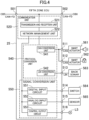
- Fig. 3 illustrates a functional configuration example of the third zone ECU 23.
- the description of the same configuration as that of the first zone ECU 21 may be omitted.
- the third zone ECU 23 includes a communication unit 320, a protocol conversion unit 340, and a signal conversion unit 350.
- the protocol conversion unit 340 includes a CAN conversion unit 341.
- the signal conversion unit 350 includes a digital input circuit 351, an analog input circuit 352, and a control output circuit 353.
- the third zone ECU 23 includes a trunk port 301 to which the Ethernet cable EB3 is connected and a trunk port 302 to which the Ethernet cable EB5 is connected.
- the trunk port 301 and the trunk port 302 are ports to which a trunk network signal is input and output.
- the third zone ECU 23 includes communication ports 311 to 315 as device ports.
- the third zone ECU 23 inputs and outputs CAN signals via the communication ports 311 and 312, inputs digital control signals via the communication port 313, inputs analog control signals via the communication port 314, and outputs analog control signals via the communication port 315.
- the communication port 311 is connected to a collision detection unit 361 that detects a collision of the vehicle 1.
- the communication port 312 is connected to a smart actuator 362 for operating a left-front turn light L3 on the left side of the vehicle.
- the communication port 313 is connected to a switch 363 (for example, a washer level switch, a hood switch, or the like).
- the communication port 314 is connected to a sensor 364 (for example, an outside air temperature sensor, an air flow sensor, or the like).
- the communication port 315 is connected to an actuator 365 (for example, a horn, a keyless buzzer, or the like).
- the communication unit 320 includes a third transmission and reception unit 321 connected to the trunk port 301, a fourth transmission and reception unit 322 connected to the trunk port 302, and a network management unit 323.
- the configuration and function related to the invention of the present application are similar to those of the communication unit 120 of the first zone ECU 21 described above, and thus the detailed description thereof will be omitted here.
- the difference is that the second transmission and reception unit 122 conforms to the CAN-FD protocol in the first zone ECU 21, whereas the fourth transmission and reception unit 322 conforms to the Ethernet protocol in the third zone ECU 23.
- the configuration of the transmission and reception circuit and the delay information conforming to each communication scheme can be replaced on the basis of the conventional technique.
- the protocol conversion unit 340 performs protocol conversion so that data can be exchanged between communication schemes.
- the difference between the protocol conversion unit 340 and the protocol conversion unit 140 of the first zone ECU 21 will be mainly described, and the description of the same contents may be omitted.
- the third zone ECU 23 relays between an Ethernet signal and an Ethernet signal in "(a) relay function". Consequently, unlike the protocol conversion unit 140 described above, the protocol conversion unit 340 does not require protocol conversion in the relay process.
- "(b) Distribution function” and "(c) integration function" in the third zone ECU 23 have the same contents as those in the first zone ECU 21 described above, and thus the detailed description thereof will be omitted here.
- the fourth zone ECU 24 has the same configuration as the third zone ECU 23, and the same reference signs are given to in-vehicle devices connected to the respective zone ECUs 23 and 24.
- the detailed description of the fourth zone ECU 24 will be omitted.
- the third zone ECU 23 and the fourth zone ECU 24 can have completely different configurations, and/or different in-vehicle devices can be connected to the respective zone ECUs 23 and 24.
- the right-front turn lamp that is provided on the right side of the vehicle and is connected to the fourth zone ECU 24 is distinguished from the left-front turn light L3 connected to the third zone ECU 23, and is denoted by a reference sign L4.
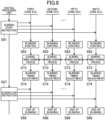
- Fig. 4 illustrates a functional configuration example of the fifth zone ECU 25.
- the description of the same configuration as that of the first zone ECU 21 and/or the third zone ECU 23 may be omitted.
- the fifth zone ECU 25 includes a communication unit 520, a protocol conversion unit 540, and a signal conversion unit 550.
- the protocol conversion unit 540 includes a CAN conversion unit 541 and a LIN conversion unit 542.
- the signal conversion unit 550 includes a digital input circuit 551, an analog input circuit 552, and a control output circuit 553.
- the fifth zone ECU 25 includes a trunk port 501 to which the CAN-FD cable CB5 is connected and a trunk port 502 to which the CAN-FD cable CB8 is connected.
- a CAN-FD signal is input and output to and from the trunk port 501 and the trunk port 502, and the trunk port 501 and the trunk port 502 are directly connected.
- the fifth zone ECU 25 includes communication ports 511 to 516 as device ports.
- the fifth zone ECU 25 inputs and outputs CAN signals via the communication ports 511 and 512, inputs and outputs LIN signals via the communication port 513, inputs digital control signals via the communication port 514, inputs analog control signals via the communication port 515, and outputs analog control signals via the communication port 516.
- the communication port 511 is connected to a smart actuator 561 for emitting a buzzer sound or the like.
- the communication port 512 is connected to a smart actuator 562 for locking a side door.
- the communication port 513 is connected to a back sonar device 563.
- the communication port 514 is connected to a switch 564.
- the communication port 515 is connected to a sensor 565 (for example, a fuel sensor, a kick sensor, or the like).
- the communication port 516 is connected to a left-rear turn light L5 on the left rear of the vehicle.
- the symbol mark of the sound source mechanism is illustrated in addition to the smart actuator 561 for easy understanding of the description.
- the symbol mark of the lock mechanism is illustrated.
- the communication unit 520 includes a transmission and reception unit 521 connected to a common communication line connecting the trunk port 501 and the trunk port 502 and a network management unit 522.
- the transmission and reception unit 521 includes, for example, a coding circuit that generates a CAN-FD signal, a driver circuit and a receiver circuit connected to the common communication line, and a decoding circuit that decodes the CAN-FD signal received by the receiver circuit.
- the protocol conversion unit 540 performs protocol conversion so that data can be exchanged between communication schemes.
- the difference between the protocol conversion unit 540 and the protocol conversion unit 140 of the first zone ECU 21 will be mainly described, and the description of the same contents may be omitted.
- the sixth zone ECU 26 has the same configuration as the fifth zone ECU 25, and the same reference signs are given to in-vehicle devices connected to the respective zone ECUs 25 and 26.
- the detailed description of the sixth zone ECU 26 will be omitted.
- the fifth zone ECU 25 and the sixth zone ECU 26 can have completely different configurations, and/or different in-vehicle devices can be connected to the respective zone ECUs 25 and 26.
- the right-rear turn lamp that is provided on the right rear side of the vehicle and is connected to the sixth zone ECU 26 is distinguished from the left-rear turn light L5 connected to the fifth zone ECU 25, and is denoted by a reference sign L6.
- a relay device such as a network hub device and/or a gateway device is interposed between the central processing unit and an in-vehicle device or an ECU that controls the in-vehicle device.
- relay devices such as network hub devices or gateway devices interposed between the central processing unit and the in-vehicle device may have different configurations.
- lighting timings deviate from each other in a plurality of turn lights, and/or buzzer sound timings deviate from each other in a plurality of sound generation devices.
- the invention of the present application is characterized in that, for example, the central processing unit 10 transmits a blinking control signal to each zone ECU 2, and then each zone ECU 2 transmits blinking timing information, and the timing is readjusted on the basis of the blinking timing information.
- Fig. 5 is obtained by extracting a network configuration from the central processing unit 10 to the turn lights L1 to L6 in Fig. 1 .
- the turn lights L1 to L6 are connected in a daisy chain layout from the central processing unit 10.
- the central processing unit 10 includes a turn-light control unit 11 that outputs a blinking control signal indicating the start of blinking, end of blinking, and/or blinking timing of the turn light.
- turn lights L1 to L6 may be simply referred to as "turn light L" in a case where the turn lights L1 to L6 are described without distinction, a case where the turn lights L1 to L6 are collectively described, or the like.
- the central processing unit and the first to fourth zone ECUs 21 to 24 are connected by a time synchronization Ethernet network. That is, when a blinking control signal is transmitted from the turn-light control unit 11 to the first to fourth zone ECUs 21 to 24, substantially synchronized blinking control signals are output from the first to fourth zone ECUs 21 to 24.
- the first zone ECU 21 and the left-side turn light L1, the second zone ECU 22 and the right-side turn light L2, the third zone ECU 23 and the left-front turn light L3, the fourth zone ECU 24 and the right-front turn light L4, the first zone ECU 24 and the fifth zone ECU 24, the fifth zone ECU 24 and the left-rear turn light L5, the second zone ECU 22 and the sixth zone ECU 26, and the sixth zone ECU 26 and the right-rear turn light L6 are connected by a time asynchronous CAN-FD or CAN network. Furthermore, as illustrated in Fig.
- the communication paths from the first to fourth zone ECUs 21 to 24 to the turn lights L1 to L6 have different communication path lengths and interposing devices (including ECUs). Consequently, even when substantially synchronized blinking control signals are output from the first to fourth zone ECUs 21 to 24, the blinking timings of the turn lights L1 to L6 may be different from each other.
- the turn lights L1 to L4 are examples of blinkers.
- the blinking control of the turn lights L1 to L6 is executed in a flow as illustrated in Fig. 6 .
- step S61 of Fig. 6 the central processing unit 10 transmits a blinking start instruction to the zone ECUs 21 to 26 as a blinking control signal.
- step S62 when receiving the blinking start instruction from the central processing unit 10, the zone ECUs 2 execute blinking control of the turn lights L1 to L6 connected to themselves.
- the first zone ECU 21 outputs a blinking control signal to the left-side turn light L1
- the second zone ECU 22 outputs a blinking control signal to the right-side turn light L2
- the third zone ECU 23 outputs a blinking control signal for the left-front turn light L3 to the smart actuator 362
- the fourth zone ECU 24 outputs a blinking control signal for the right-front turn light L4 to the smart actuator 362
- the fifth zone ECU 25 outputs a blinking control signal to the left-rear turn light L5
- the sixth zone ECU 26 outputs a blinking control signal to the right-rear turn light L6.
- each zone ECU 2 transmits blinking timing information of the turn light L controlled by each zone ECU 2 to the central processing unit 10.
- the first zone ECU 21 transmits, to the central processing unit 10, a time t31 from when the first zone ECU 21 outputs a blinking control signal to when the left-side turn light L1 blinks as the blinking timing information of the left-side turn light L1.
- the second zone ECU 22 to the sixth zone ECU 26 transmit, to the central processing unit 10, times t32 to t36 from when the second zone ECU 22 to the sixth zone ECU 26 output a blinking control signal to when the turn lights blink, as the blinking timing information of the turn lights connected to the second zone ECU 22 to the sixth zone ECU 26.
- the turn light is controlled via the smart actuator 362. Consequently, the third and fourth zone ECUs 23 and 24 can include the signal processing time of the smart actuator 362 as the blinking timing information. Specifically, for example, the third zone ECU 23 can receive the blinking timing information of the left-front turn light L3 from the smart actuator 362, and calculate the time t23 on the basis of the information.
- the fifth zone ECU 25 is connected to the first zone ECU 21 by the CAN-FD cable CB5, a delay is generated accordingly. The fifth zone ECU 25 can thus include the communication delay time with the first zone ECU 21 as the blinking timing information.
- step S64 the central processing unit 10 calculates a timing adjustment signal for adjusting the timing so that the blinking timings of the turn lights L1 to L6 match on the basis of the blinking timing of each turn light received from each zone ECU 2. Thereafter, in step S65, the calculated timing adjustment signal is transmitted to each zone ECU 2. As a result of calculating the timing adjustment signal, the timing adjustment signal does not need to be output to the turn light L in which the deviation of the blinking timing is within a predetermined allowable range.
- the timing adjustment signal is an example of adjustment information.
- each zone ECU 2 outputs a blinking control signal whose blinking timing has been adjusted to the turn light on the basis of the timing adjustment signal received from the central processing unit 10.
- each zone ECU 2 ends blinking of the turn light (step S68).
- the central processing unit 10 transmits a blinking control signal to each zone ECU 2, and then receives the blinking timing information from each zone ECU 2.
- the central processing unit 10 transmits a timing adjustment signal for adjusting the blinking timing on the basis of the received blinking timing information to each zone ECU 2.
- the present embodiment is characterized in that communication jitter and/or a control timing are managed on the side of the zone ECU 2 so as not to deviate by a predetermined time (for example, 10 msec) or longer as the synchronization control of the turn lights L1 to L6 after the central processing unit 10 transmits a base blinking control signal.
- a predetermined time for example, 10 msec
- Fig. 7 illustrates a configuration example of a network from the central processing unit 10 to the turn lights L1 to L6 in the present embodiment.
- differences from the first embodiment will be mainly described, and the description of the same configurations and operations may be omitted.
- Fig. 7 The configuration of Fig. 7 is different from that of the first embodiment in that the zone ECUs 2 are connected by a network, and the zone ECUs 2 can communicate with each other without passing through the central processing unit 10.
- the first zone ECU 21 and the second zone ECU 22 are connected by an Ethernet cable EB7
- the first zone ECU 21 and the fourth zone ECU 24 are connected by an Ethernet cable EB6.
- the third zone ECU 23 and the fourth zone ECU 24 are connected by the Ethernet cable EB5
- the fifth zone ECU 25 and the sixth zone ECU 26 are connected by the CAN-FD cable CB8.
- each zone ECU 2 and the connection configuration between each zone ECU 2 and the turn light L are the same as those in the first embodiment described above, and the detailed description thereof will be omitted here.
- the network in which the zone ECUs 2 can communicate with each other without processing of the central processing unit 10 interposed therebetween is referred to as "local network".
- the Ethernet cables EB5 to EB7 are examples of cables constituting the local network
- the first zone ECU 21 to the fourth zone ECU 24 are connected by the local network. That is, the first zone ECU 21 to the fourth zone ECU 24 are examples of a first zone ECU.
- the information transmitted and received between the first zone ECU 21 to the fourth zone ECU 24 via the Ethernet cables EB5 to EB7 without the processing of the central processing unit 10 interposed therebetween is an example of information transmitted and received via the local network.
- Fig. 8 illustrates an example of a blinking control operation of a turn light in a vehicle control system described in the second embodiment. Note that, in Fig. 8 , the same operations as those in Fig. 6 are denoted by the same reference signs, and the description thereof may be omitted.
- step S61 of Fig. 8 as in the case of Fig. 6 , the central processing unit 10 transmits a blinking start instruction to each zone ECU 2 as a blinking control signal.
- step S62 when receiving the blinking start instruction from the central processing unit 10, the zone ECUs 2 execute blinking control of the turn lights L1 to L6 connected to themselves.
- each zone ECU 2 performs a blinking-timing information sharing process of sharing blinking timing information of the turn light L controlled by each ECU 2.
- the blinking timing information can be shared with each other without the central processing unit 10 interposed therebetween, or the blinking timing information can be shared with each other with the central processing unit 10 interposed as a hub device.
- the transmission and reception of information via the local network of the present disclosure also includes a case where information is transmitted and received between the zone ECUs 2 with the central processing unit 10 interposed as a hub device, that is, by using the central processing unit 10 as a hub device without the processing of the central processing unit 10 interposed therebetween.
- the zone ECUs 2 compare the blinking timing of the turn light L of another zone ECU 2 with the blinking timing of the turn light L of the own ECU 2, and perform an adjustment process of adjusting the blinking timing of the turn light L of the own ECU.
- the method of adjusting the blinking timing is only required to be able to adjust the blinking timing, and a specific method is not particularly limited.
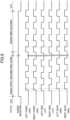
- Fig. 9 illustrates an example of a method of adjusting a blinking timing.
- the blinking timing of the left-side turn light L1 and the blinking timing of the right-side turn light L2 are substantially the same, and their blinking start time is the earliest.
- the left-front turn light L3 and the right-front turn light L4 start blinking substantially simultaneously
- the left-rear turn light L5 and the right-rear turn light L6 start blinking substantially simultaneously.
- step S74 is performed during a "timing adjustment" period in Fig. 9 .
- the zone ECUs 2 compare the blinking timing of the turn light L of another zone ECU 2 with the blinking timing of the turn light L of the own ECU 2, and execute control to advance a turn-off time in accordance with the earliest blinking timing.
- the turn-off times of the respective turn lights L can be the same.
- the pitch of turning on and off the turn light L can be set in advance. Consequently, in a case where the turn-off time is advanced, each zone ECU 2 can repeat turning on and off the turn light L at a predetermined pitch by setting the turn-off time as a starting point.
- the turn-on and turn-off times of the turn lights L can be the same, that is, the blinking timings can match.
- each zone ECU 2 ends blinking of the turn light (step S68).
- timing adjustment is the control to advance the turn-off time in accordance with the earliest blinking timing, but the present invention is not limited thereto.
- the zone ECU or the smart actuator that outputs a blinking control signal at the timing farthest from a reference timing can adjust the output timing to the reference timing.
- the reference timing can be set in advance, or can be obtained by calculation, for example, like an average value of timing information received from each zone ECU.
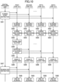
- Fig. 10 illustrates another example of the blinking control operation of a turn light in the vehicle control system described in the second embodiment. Note that, in Fig. 10 , the same operations as those in Fig. 8 are denoted by the same reference signs, and the description thereof may be omitted.
- the method of adjusting the blinking timing of the turn light L is different from that in the case of the blinking control operation of Fig. 8 .
- the blinking timing of each zone ECU 2 is collected in a master ECU (the first zone ECU 21 in Fig. 10 ) that is any one of the first to sixth zone ECUs 21 to 26 (step S83).
- the master ECU performs arithmetic processing for adjusting the blinking timing of each turn light L on the basis of the timing information of each zone ECU 2.
- the master ECU transmits an adjustment signal for adjusting the timing of each turn light L to each zone ECU 2 on the basis of the result of the arithmetic processing.
- each zone ECU 2 outputs a blinking control signal whose blinking timing has been adjusted to the turn light on the basis of the timing adjustment signal received from the master ECU.
- each zone ECU 2 ends blinking of the turn light (step S68).
- the blinking control operation itself is incorporated in the central processing unit 10, but fine timing adjustment is handled on the zone ECU side.
- the technology of the present disclosure can also be applied to the synchronous control of an actuator other than the turn light L.
- the smart actuator for example, see 163, 561 in Fig. 1
- the sound generation device can adopt the same control as that of the turn light described above.
- the first zone ECU 21 and the second zone ECU 22 are connected via the local network, the first zone ECU 21 and the second zone ECU 22 share the drive timing information of the actuator 163 via the local network.
- the timing signal of the actuator 163 in the first zone ECU 21 is adjusted on the basis of the shared information.
- the timing signal of the actuator 163 in the second zone ECU 21 is adjusted on the basis of the shared information.
- either the first zone ECU 21 or the second zone ECU 22 can be used as the master ECU.
- the technology disclosed herein is useful for designing a vehicle control system.
Landscapes
- Engineering & Computer Science (AREA)
- Mechanical Engineering (AREA)
- Theoretical Computer Science (AREA)
- Computer Networks & Wireless Communication (AREA)
- Signal Processing (AREA)
- Automation & Control Theory (AREA)
- Physics & Mathematics (AREA)
- General Engineering & Computer Science (AREA)
- General Physics & Mathematics (AREA)
- Small-Scale Networks (AREA)
- Lighting Device Outwards From Vehicle And Optical Signal (AREA)
Claims (3)
- Système de commande de véhicule, le système comprenant :une pluralité d'unités de commande électronique (UCE) de zone (2), dont chacune est disposée dans chaque zone prédéfinie d'un véhicule,une unité centrale de traitement (10) connectée aux UCE de zone par l'intermédiaire d'un réseau à ressources partagées (EB1-EB4) de synchronisation de temps, etune pluralité d'actionneurs (L1-L6) fonctionnant en synchronisation,les UCE de zone (2) comprenant une pluralité de premières UCE de zone (21-24) destinées à délivrer un signal de temporisation servant à faire fonctionner les actionneurs (L1-L4) connectés à chacune d'entre elles en fonction d'un signal de commande reçu à partir de l'unité centrale de traitement (10),chacune des premières UCE de zone (21-24) et chacun des actionneurs (L1-L4) étant connectés par un réseau asynchrone temporel,ledit système de commande de véhicule étant caractérisé en ce quel'unité centrale de traitement (10) envoie, aux premières UCE de zone (21-24) et à des secondes UCE de zone (25, 26), une instruction de démarrage de fonctionnement en tant que signal de commande servant à démarrer le fonctionnement du premier actionneur (L1 à L4) et d'un second actionneur (L5, L6),les premières UCE de zone (21-24) sont conçues pour être connectées les unes aux autres par l'intermédiaire d'un réseau local (EB5-EB7) sans l'unité centrale de traitement (10), pour partager des informations de temporisation d'entraînement des actionneurs (L1-L4), en fonction de l'instruction de démarrage de fonctionnement, avec une autre première UCE de zone (21-24) par l'intermédiaire du réseau local (EB5-EB7), et pour régler le signal de temporisation des premières UCE de zone (21-24) en fonction des informations partagées.
- Le système de commande de véhicule selon la revendication 1, dans lequel
le premier actionneur (L1-L4) et le second actionneur (L5, L6) sont des clignotants. - Le système de commande de véhicule selon la revendication 2, dans lequel chacune des premières UCE de zone (21-24) est conçue de telle façon que, au cas où le temps fixé de clignotement d'une autre première UCE de zone (21-24) serait antérieur au temps fixé de clignotement du la première UCE de zone (21-24), un temps de démarrage de coupure pendant la période de clignotement est amené à correspondre à un temps de démarrage de coupure d'une autre première UCE de zone (21-24).
Applications Claiming Priority (2)
| Application Number | Priority Date | Filing Date | Title |
|---|---|---|---|
| JP2019141114A JP7298372B2 (ja) | 2019-07-31 | 2019-07-31 | 車両制御システム |
| PCT/JP2020/028184 WO2021020221A1 (fr) | 2019-07-31 | 2020-07-21 | Système de commande de véhicule |
Publications (3)
| Publication Number | Publication Date |
|---|---|
| EP4001011A1 EP4001011A1 (fr) | 2022-05-25 |
| EP4001011A4 EP4001011A4 (fr) | 2022-09-21 |
| EP4001011B1 true EP4001011B1 (fr) | 2024-04-03 |
Family
ID=74230615
Family Applications (1)
| Application Number | Title | Priority Date | Filing Date |
|---|---|---|---|
| EP20848129.1A Active EP4001011B1 (fr) | 2019-07-31 | 2020-07-21 | Système de commande de véhicule |
Country Status (5)
| Country | Link |
|---|---|
| US (1) | US12263783B2 (fr) |
| EP (1) | EP4001011B1 (fr) |
| JP (1) | JP7298372B2 (fr) |
| CN (1) | CN114174124B (fr) |
| WO (1) | WO2021020221A1 (fr) |
Families Citing this family (3)
| Publication number | Priority date | Publication date | Assignee | Title |
|---|---|---|---|---|
| DE102021104421A1 (de) * | 2021-02-24 | 2022-08-25 | Robert Bosch Gesellschaft mit beschränkter Haftung | Verfahren zum Betreiben eines Bordnetzes, Bordnetz, und Rechensystem |
| JP7562594B2 (ja) * | 2022-03-31 | 2024-10-07 | 本田技研工業株式会社 | 車両通信システム、車両通信方法、および制御装置 |
| CN116968665A (zh) * | 2023-07-20 | 2023-10-31 | 大运汽车股份有限公司 | 一种车辆解闭锁时灯光提醒系统 |
Family Cites Families (16)
| Publication number | Priority date | Publication date | Assignee | Title |
|---|---|---|---|---|
| JPH11115627A (ja) * | 1997-10-14 | 1999-04-27 | Nippon Soken Inc | 負荷動作制御装置 |
| JP2001138804A (ja) * | 1999-11-11 | 2001-05-22 | Yazaki Corp | 車載通信ネットワークにおけるランプ負荷の点滅制御方法ならびにそのシステム |
| DE102004022555B4 (de) * | 2004-05-07 | 2006-04-06 | Siemens Ag | Vorrichtung und Verfahren zum Synchronisieren einer Blinkerfrequenz mit einer Zentralblinkfrequenz |
| JP4324795B2 (ja) * | 2004-12-10 | 2009-09-02 | 三菱自動車工業株式会社 | 車載制御装置 |
| JP4767008B2 (ja) * | 2005-12-14 | 2011-09-07 | 株式会社オートネットワーク技術研究所 | 負荷同期制御システム |
| EP2509263B1 (fr) * | 2009-12-02 | 2016-08-10 | Toyota Jidosha Kabushiki Kaisha | Système de réseau de communication de données |
| US8504864B2 (en) * | 2010-12-01 | 2013-08-06 | GM Global Technology Operations LLC | Data sensor coordination using time synchronization in a multi-bus controller area network system |
| JP5648612B2 (ja) * | 2011-09-11 | 2015-01-07 | 株式会社デンソー | 車載機器制御システム |
| DE102012204586B4 (de) * | 2012-03-22 | 2025-02-27 | Bayerische Motoren Werke Aktiengesellschaft | Gateway, Knoten und Verfahren für ein Fahrzeug |
| JP6485306B2 (ja) * | 2015-09-25 | 2019-03-20 | 株式会社デンソー | 制御システム |
| FR3048392B1 (fr) * | 2016-03-02 | 2019-04-05 | Valeo Vision | Projecteur anti-eblouissement |
| JP6962697B2 (ja) | 2016-05-27 | 2021-11-05 | パナソニック インテレクチュアル プロパティ コーポレーション オブ アメリカPanasonic Intellectual Property Corporation of America | ネットワークハブ、転送方法及び車載ネットワークシステム |
| JP6635023B2 (ja) * | 2016-12-26 | 2020-01-22 | トヨタ自動車株式会社 | 車両の車線変更支援装置 |
| JP6443830B1 (ja) * | 2017-10-30 | 2018-12-26 | マツダ株式会社 | 車両用ランプ装置 |
| JP6443831B1 (ja) * | 2017-10-30 | 2018-12-26 | マツダ株式会社 | 車両用ランプ装置 |
| JP7434728B2 (ja) * | 2019-06-13 | 2024-02-21 | マツダ株式会社 | 車載ネットワークシステム |
-
2019
- 2019-07-31 JP JP2019141114A patent/JP7298372B2/ja active Active
-
2020
- 2020-07-21 WO PCT/JP2020/028184 patent/WO2021020221A1/fr not_active Ceased
- 2020-07-21 US US17/631,501 patent/US12263783B2/en active Active
- 2020-07-21 EP EP20848129.1A patent/EP4001011B1/fr active Active
- 2020-07-21 CN CN202080054576.XA patent/CN114174124B/zh active Active
Also Published As
| Publication number | Publication date |
|---|---|
| WO2021020221A1 (fr) | 2021-02-04 |
| JP2021024316A (ja) | 2021-02-22 |
| US12263783B2 (en) | 2025-04-01 |
| US20220274521A1 (en) | 2022-09-01 |
| JP7298372B2 (ja) | 2023-06-27 |
| EP4001011A4 (fr) | 2022-09-21 |
| CN114174124A (zh) | 2022-03-11 |
| EP4001011A1 (fr) | 2022-05-25 |
| CN114174124B (zh) | 2024-02-20 |
Similar Documents
| Publication | Publication Date | Title |
|---|---|---|
| EP4005871B1 (fr) | Système de commande de véhicule | |
| EP4007216B1 (fr) | Système de commande de véhicule et procédé de conception de système de commande de véhicule | |
| EP4007217B1 (fr) | Système de commande de véhicule et procédé de conception pour système de commande de véhicule | |
| EP4001011B1 (fr) | Système de commande de véhicule | |
| EP3998748B1 (fr) | Système de réseau à bord d'un véhicule | |
| EP3993324A1 (fr) | Dispositif concentrateur de réseau | |
| EP3998745B1 (fr) | Dispositif concentrateur de réseau |
Legal Events
| Date | Code | Title | Description |
|---|---|---|---|
| STAA | Information on the status of an ep patent application or granted ep patent |
Free format text: STATUS: THE INTERNATIONAL PUBLICATION HAS BEEN MADE |
|
| PUAI | Public reference made under article 153(3) epc to a published international application that has entered the european phase |
Free format text: ORIGINAL CODE: 0009012 |
|
| STAA | Information on the status of an ep patent application or granted ep patent |
Free format text: STATUS: REQUEST FOR EXAMINATION WAS MADE |
|
| 17P | Request for examination filed |
Effective date: 20220221 |
|
| AK | Designated contracting states |
Kind code of ref document: A1 Designated state(s): AL AT BE BG CH CY CZ DE DK EE ES FI FR GB GR HR HU IE IS IT LI LT LU LV MC MK MT NL NO PL PT RO RS SE SI SK SM TR |
|
| A4 | Supplementary search report drawn up and despatched |
Effective date: 20220822 |
|
| RIC1 | Information provided on ipc code assigned before grant |
Ipc: B60W 50/00 20060101ALI20220816BHEP Ipc: B60W 50/029 20120101ALI20220816BHEP Ipc: H04L 12/40 20060101ALI20220816BHEP Ipc: B60Q 1/50 20060101ALI20220816BHEP Ipc: B60W 30/18 20120101ALI20220816BHEP Ipc: B60Q 1/38 20060101ALI20220816BHEP Ipc: H04L 12/28 20060101ALI20220816BHEP Ipc: B60R 16/023 20060101ALI20220816BHEP Ipc: B60Q 1/34 20060101AFI20220816BHEP |
|
| DAV | Request for validation of the european patent (deleted) | ||
| DAX | Request for extension of the european patent (deleted) | ||
| GRAP | Despatch of communication of intention to grant a patent |
Free format text: ORIGINAL CODE: EPIDOSNIGR1 |
|
| STAA | Information on the status of an ep patent application or granted ep patent |
Free format text: STATUS: GRANT OF PATENT IS INTENDED |
|
| INTG | Intention to grant announced |
Effective date: 20240118 |
|
| GRAS | Grant fee paid |
Free format text: ORIGINAL CODE: EPIDOSNIGR3 |
|
| GRAA | (expected) grant |
Free format text: ORIGINAL CODE: 0009210 |
|
| STAA | Information on the status of an ep patent application or granted ep patent |
Free format text: STATUS: THE PATENT HAS BEEN GRANTED |
|
| AK | Designated contracting states |
Kind code of ref document: B1 Designated state(s): AL AT BE BG CH CY CZ DE DK EE ES FI FR GB GR HR HU IE IS IT LI LT LU LV MC MK MT NL NO PL PT RO RS SE SI SK SM TR |
|
| REG | Reference to a national code |
Ref country code: CH Ref legal event code: EP |
|
| REG | Reference to a national code |
Ref country code: DE Ref legal event code: R096 Ref document number: 602020028508 Country of ref document: DE |
|
| REG | Reference to a national code |
Ref country code: IE Ref legal event code: FG4D |
|
| REG | Reference to a national code |
Ref country code: LT Ref legal event code: MG9D |
|
| REG | Reference to a national code |
Ref country code: NL Ref legal event code: MP Effective date: 20240403 |
|
| REG | Reference to a national code |
Ref country code: AT Ref legal event code: MK05 Ref document number: 1671928 Country of ref document: AT Kind code of ref document: T Effective date: 20240403 |
|
| PG25 | Lapsed in a contracting state [announced via postgrant information from national office to epo] |
Ref country code: NL Free format text: LAPSE BECAUSE OF FAILURE TO SUBMIT A TRANSLATION OF THE DESCRIPTION OR TO PAY THE FEE WITHIN THE PRESCRIBED TIME-LIMIT Effective date: 20240403 |
|
| PG25 | Lapsed in a contracting state [announced via postgrant information from national office to epo] |
Ref country code: NL Free format text: LAPSE BECAUSE OF FAILURE TO SUBMIT A TRANSLATION OF THE DESCRIPTION OR TO PAY THE FEE WITHIN THE PRESCRIBED TIME-LIMIT Effective date: 20240403 |
|
| PG25 | Lapsed in a contracting state [announced via postgrant information from national office to epo] |
Ref country code: IS Free format text: LAPSE BECAUSE OF FAILURE TO SUBMIT A TRANSLATION OF THE DESCRIPTION OR TO PAY THE FEE WITHIN THE PRESCRIBED TIME-LIMIT Effective date: 20240803 |
|
| PG25 | Lapsed in a contracting state [announced via postgrant information from national office to epo] |
Ref country code: BG Free format text: LAPSE BECAUSE OF FAILURE TO SUBMIT A TRANSLATION OF THE DESCRIPTION OR TO PAY THE FEE WITHIN THE PRESCRIBED TIME-LIMIT Effective date: 20240403 |
|
| PG25 | Lapsed in a contracting state [announced via postgrant information from national office to epo] |
Ref country code: FI Free format text: LAPSE BECAUSE OF FAILURE TO SUBMIT A TRANSLATION OF THE DESCRIPTION OR TO PAY THE FEE WITHIN THE PRESCRIBED TIME-LIMIT Effective date: 20240403 Ref country code: HR Free format text: LAPSE BECAUSE OF FAILURE TO SUBMIT A TRANSLATION OF THE DESCRIPTION OR TO PAY THE FEE WITHIN THE PRESCRIBED TIME-LIMIT Effective date: 20240403 |
|
| PG25 | Lapsed in a contracting state [announced via postgrant information from national office to epo] |
Ref country code: GR Free format text: LAPSE BECAUSE OF FAILURE TO SUBMIT A TRANSLATION OF THE DESCRIPTION OR TO PAY THE FEE WITHIN THE PRESCRIBED TIME-LIMIT Effective date: 20240704 |
|
| PG25 | Lapsed in a contracting state [announced via postgrant information from national office to epo] |
Ref country code: PT Free format text: LAPSE BECAUSE OF FAILURE TO SUBMIT A TRANSLATION OF THE DESCRIPTION OR TO PAY THE FEE WITHIN THE PRESCRIBED TIME-LIMIT Effective date: 20240805 |
|
| PG25 | Lapsed in a contracting state [announced via postgrant information from national office to epo] |
Ref country code: ES Free format text: LAPSE BECAUSE OF FAILURE TO SUBMIT A TRANSLATION OF THE DESCRIPTION OR TO PAY THE FEE WITHIN THE PRESCRIBED TIME-LIMIT Effective date: 20240403 |
|
| PG25 | Lapsed in a contracting state [announced via postgrant information from national office to epo] |
Ref country code: CZ Free format text: LAPSE BECAUSE OF FAILURE TO SUBMIT A TRANSLATION OF THE DESCRIPTION OR TO PAY THE FEE WITHIN THE PRESCRIBED TIME-LIMIT Effective date: 20240403 |
|
| PG25 | Lapsed in a contracting state [announced via postgrant information from national office to epo] |
Ref country code: AT Free format text: LAPSE BECAUSE OF FAILURE TO SUBMIT A TRANSLATION OF THE DESCRIPTION OR TO PAY THE FEE WITHIN THE PRESCRIBED TIME-LIMIT Effective date: 20240403 |
|
| PG25 | Lapsed in a contracting state [announced via postgrant information from national office to epo] |
Ref country code: PL Free format text: LAPSE BECAUSE OF FAILURE TO SUBMIT A TRANSLATION OF THE DESCRIPTION OR TO PAY THE FEE WITHIN THE PRESCRIBED TIME-LIMIT Effective date: 20240403 |
|
| PG25 | Lapsed in a contracting state [announced via postgrant information from national office to epo] |
Ref country code: LV Free format text: LAPSE BECAUSE OF FAILURE TO SUBMIT A TRANSLATION OF THE DESCRIPTION OR TO PAY THE FEE WITHIN THE PRESCRIBED TIME-LIMIT Effective date: 20240403 |
|
| PG25 | Lapsed in a contracting state [announced via postgrant information from national office to epo] |
Ref country code: PT Free format text: LAPSE BECAUSE OF FAILURE TO SUBMIT A TRANSLATION OF THE DESCRIPTION OR TO PAY THE FEE WITHIN THE PRESCRIBED TIME-LIMIT Effective date: 20240805 Ref country code: PL Free format text: LAPSE BECAUSE OF FAILURE TO SUBMIT A TRANSLATION OF THE DESCRIPTION OR TO PAY THE FEE WITHIN THE PRESCRIBED TIME-LIMIT Effective date: 20240403 Ref country code: NO Free format text: LAPSE BECAUSE OF FAILURE TO SUBMIT A TRANSLATION OF THE DESCRIPTION OR TO PAY THE FEE WITHIN THE PRESCRIBED TIME-LIMIT Effective date: 20240703 Ref country code: LV Free format text: LAPSE BECAUSE OF FAILURE TO SUBMIT A TRANSLATION OF THE DESCRIPTION OR TO PAY THE FEE WITHIN THE PRESCRIBED TIME-LIMIT Effective date: 20240403 Ref country code: IS Free format text: LAPSE BECAUSE OF FAILURE TO SUBMIT A TRANSLATION OF THE DESCRIPTION OR TO PAY THE FEE WITHIN THE PRESCRIBED TIME-LIMIT Effective date: 20240803 Ref country code: HR Free format text: LAPSE BECAUSE OF FAILURE TO SUBMIT A TRANSLATION OF THE DESCRIPTION OR TO PAY THE FEE WITHIN THE PRESCRIBED TIME-LIMIT Effective date: 20240403 Ref country code: GR Free format text: LAPSE BECAUSE OF FAILURE TO SUBMIT A TRANSLATION OF THE DESCRIPTION OR TO PAY THE FEE WITHIN THE PRESCRIBED TIME-LIMIT Effective date: 20240704 Ref country code: FI Free format text: LAPSE BECAUSE OF FAILURE TO SUBMIT A TRANSLATION OF THE DESCRIPTION OR TO PAY THE FEE WITHIN THE PRESCRIBED TIME-LIMIT Effective date: 20240403 Ref country code: ES Free format text: LAPSE BECAUSE OF FAILURE TO SUBMIT A TRANSLATION OF THE DESCRIPTION OR TO PAY THE FEE WITHIN THE PRESCRIBED TIME-LIMIT Effective date: 20240403 Ref country code: CZ Free format text: LAPSE BECAUSE OF FAILURE TO SUBMIT A TRANSLATION OF THE DESCRIPTION OR TO PAY THE FEE WITHIN THE PRESCRIBED TIME-LIMIT Effective date: 20240403 Ref country code: BG Free format text: LAPSE BECAUSE OF FAILURE TO SUBMIT A TRANSLATION OF THE DESCRIPTION OR TO PAY THE FEE WITHIN THE PRESCRIBED TIME-LIMIT Effective date: 20240403 Ref country code: AT Free format text: LAPSE BECAUSE OF FAILURE TO SUBMIT A TRANSLATION OF THE DESCRIPTION OR TO PAY THE FEE WITHIN THE PRESCRIBED TIME-LIMIT Effective date: 20240403 Ref country code: RS Free format text: LAPSE BECAUSE OF FAILURE TO SUBMIT A TRANSLATION OF THE DESCRIPTION OR TO PAY THE FEE WITHIN THE PRESCRIBED TIME-LIMIT Effective date: 20240703 |
|
| REG | Reference to a national code |
Ref country code: DE Ref legal event code: R097 Ref document number: 602020028508 Country of ref document: DE |
|
| PG25 | Lapsed in a contracting state [announced via postgrant information from national office to epo] |
Ref country code: DK Free format text: LAPSE BECAUSE OF FAILURE TO SUBMIT A TRANSLATION OF THE DESCRIPTION OR TO PAY THE FEE WITHIN THE PRESCRIBED TIME-LIMIT Effective date: 20240403 |
|
| PG25 | Lapsed in a contracting state [announced via postgrant information from national office to epo] |
Ref country code: EE Free format text: LAPSE BECAUSE OF FAILURE TO SUBMIT A TRANSLATION OF THE DESCRIPTION OR TO PAY THE FEE WITHIN THE PRESCRIBED TIME-LIMIT Effective date: 20240403 |
|
| PG25 | Lapsed in a contracting state [announced via postgrant information from national office to epo] |
Ref country code: RO Free format text: LAPSE BECAUSE OF FAILURE TO SUBMIT A TRANSLATION OF THE DESCRIPTION OR TO PAY THE FEE WITHIN THE PRESCRIBED TIME-LIMIT Effective date: 20240403 Ref country code: SK Free format text: LAPSE BECAUSE OF FAILURE TO SUBMIT A TRANSLATION OF THE DESCRIPTION OR TO PAY THE FEE WITHIN THE PRESCRIBED TIME-LIMIT Effective date: 20240403 |
|
| PG25 | Lapsed in a contracting state [announced via postgrant information from national office to epo] |
Ref country code: SM Free format text: LAPSE BECAUSE OF FAILURE TO SUBMIT A TRANSLATION OF THE DESCRIPTION OR TO PAY THE FEE WITHIN THE PRESCRIBED TIME-LIMIT Effective date: 20240403 |
|
| PG25 | Lapsed in a contracting state [announced via postgrant information from national office to epo] |
Ref country code: SM Free format text: LAPSE BECAUSE OF FAILURE TO SUBMIT A TRANSLATION OF THE DESCRIPTION OR TO PAY THE FEE WITHIN THE PRESCRIBED TIME-LIMIT Effective date: 20240403 Ref country code: SK Free format text: LAPSE BECAUSE OF FAILURE TO SUBMIT A TRANSLATION OF THE DESCRIPTION OR TO PAY THE FEE WITHIN THE PRESCRIBED TIME-LIMIT Effective date: 20240403 Ref country code: RO Free format text: LAPSE BECAUSE OF FAILURE TO SUBMIT A TRANSLATION OF THE DESCRIPTION OR TO PAY THE FEE WITHIN THE PRESCRIBED TIME-LIMIT Effective date: 20240403 Ref country code: EE Free format text: LAPSE BECAUSE OF FAILURE TO SUBMIT A TRANSLATION OF THE DESCRIPTION OR TO PAY THE FEE WITHIN THE PRESCRIBED TIME-LIMIT Effective date: 20240403 Ref country code: DK Free format text: LAPSE BECAUSE OF FAILURE TO SUBMIT A TRANSLATION OF THE DESCRIPTION OR TO PAY THE FEE WITHIN THE PRESCRIBED TIME-LIMIT Effective date: 20240403 |
|
| PG25 | Lapsed in a contracting state [announced via postgrant information from national office to epo] |
Ref country code: MC Free format text: LAPSE BECAUSE OF FAILURE TO SUBMIT A TRANSLATION OF THE DESCRIPTION OR TO PAY THE FEE WITHIN THE PRESCRIBED TIME-LIMIT Effective date: 20240403 |
|
| PLBE | No opposition filed within time limit |
Free format text: ORIGINAL CODE: 0009261 |
|
| STAA | Information on the status of an ep patent application or granted ep patent |
Free format text: STATUS: NO OPPOSITION FILED WITHIN TIME LIMIT |
|
| REG | Reference to a national code |
Ref country code: CH Ref legal event code: PL |
|
| 26N | No opposition filed |
Effective date: 20250106 |
|
| PG25 | Lapsed in a contracting state [announced via postgrant information from national office to epo] |
Ref country code: LU Free format text: LAPSE BECAUSE OF NON-PAYMENT OF DUE FEES Effective date: 20240721 |
|
| GBPC | Gb: european patent ceased through non-payment of renewal fee |
Effective date: 20240721 |
|
| PG25 | Lapsed in a contracting state [announced via postgrant information from national office to epo] |
Ref country code: LU Free format text: LAPSE BECAUSE OF NON-PAYMENT OF DUE FEES Effective date: 20240721 |
|
| PG25 | Lapsed in a contracting state [announced via postgrant information from national office to epo] |
Ref country code: BE Free format text: LAPSE BECAUSE OF NON-PAYMENT OF DUE FEES Effective date: 20240731 Ref country code: SI Free format text: LAPSE BECAUSE OF FAILURE TO SUBMIT A TRANSLATION OF THE DESCRIPTION OR TO PAY THE FEE WITHIN THE PRESCRIBED TIME-LIMIT Effective date: 20240403 Ref country code: CH Free format text: LAPSE BECAUSE OF NON-PAYMENT OF DUE FEES Effective date: 20240731 |
|
| PG25 | Lapsed in a contracting state [announced via postgrant information from national office to epo] |
Ref country code: FR Free format text: LAPSE BECAUSE OF NON-PAYMENT OF DUE FEES Effective date: 20240731 |
|
| PG25 | Lapsed in a contracting state [announced via postgrant information from national office to epo] |
Ref country code: GB Free format text: LAPSE BECAUSE OF NON-PAYMENT OF DUE FEES Effective date: 20240721 |
|
| REG | Reference to a national code |
Ref country code: BE Ref legal event code: MM Effective date: 20240731 |
|
| PG25 | Lapsed in a contracting state [announced via postgrant information from national office to epo] |
Ref country code: IE Free format text: LAPSE BECAUSE OF NON-PAYMENT OF DUE FEES Effective date: 20240721 |
|
| PG25 | Lapsed in a contracting state [announced via postgrant information from national office to epo] |
Ref country code: SE Free format text: LAPSE BECAUSE OF FAILURE TO SUBMIT A TRANSLATION OF THE DESCRIPTION OR TO PAY THE FEE WITHIN THE PRESCRIBED TIME-LIMIT Effective date: 20240403 |
|
| PGFP | Annual fee paid to national office [announced via postgrant information from national office to epo] |
Ref country code: DE Payment date: 20250528 Year of fee payment: 6 |
|
| PG25 | Lapsed in a contracting state [announced via postgrant information from national office to epo] |
Ref country code: IT Free format text: LAPSE BECAUSE OF FAILURE TO SUBMIT A TRANSLATION OF THE DESCRIPTION OR TO PAY THE FEE WITHIN THE PRESCRIBED TIME-LIMIT Effective date: 20240403 Ref country code: CY Free format text: LAPSE BECAUSE OF FAILURE TO SUBMIT A TRANSLATION OF THE DESCRIPTION OR TO PAY THE FEE WITHIN THE PRESCRIBED TIME-LIMIT; INVALID AB INITIO Effective date: 20200721 |
|
| PG25 | Lapsed in a contracting state [announced via postgrant information from national office to epo] |
Ref country code: HU Free format text: LAPSE BECAUSE OF FAILURE TO SUBMIT A TRANSLATION OF THE DESCRIPTION OR TO PAY THE FEE WITHIN THE PRESCRIBED TIME-LIMIT; INVALID AB INITIO Effective date: 20200721 |