EP4001015A1 - Verschiebbares handschuhfach - Google Patents
Verschiebbares handschuhfach Download PDFInfo
- Publication number
- EP4001015A1 EP4001015A1 EP21207883.6A EP21207883A EP4001015A1 EP 4001015 A1 EP4001015 A1 EP 4001015A1 EP 21207883 A EP21207883 A EP 21207883A EP 4001015 A1 EP4001015 A1 EP 4001015A1
- Authority
- EP
- European Patent Office
- Prior art keywords
- storage part
- rails
- housing
- glove box
- sliding type
- Prior art date
- Legal status (The legal status is an assumption and is not a legal conclusion. Google has not performed a legal analysis and makes no representation as to the accuracy of the status listed.)
- Granted
Links
Images
Classifications
-
- B—PERFORMING OPERATIONS; TRANSPORTING
- B60—VEHICLES IN GENERAL
- B60R—VEHICLES, VEHICLE FITTINGS, OR VEHICLE PARTS, NOT OTHERWISE PROVIDED FOR
- B60R7/00—Stowing or holding appliances inside vehicle primarily intended for personal property smaller than suit-cases, e.g. travelling articles, or maps
- B60R7/04—Stowing or holding appliances inside vehicle primarily intended for personal property smaller than suit-cases, e.g. travelling articles, or maps in driver or passenger space, e.g. using racks
- B60R7/06—Stowing or holding appliances inside vehicle primarily intended for personal property smaller than suit-cases, e.g. travelling articles, or maps in driver or passenger space, e.g. using racks mounted on or below dashboards
-
- B—PERFORMING OPERATIONS; TRANSPORTING
- B60—VEHICLES IN GENERAL
- B60R—VEHICLES, VEHICLE FITTINGS, OR VEHICLE PARTS, NOT OTHERWISE PROVIDED FOR
- B60R11/00—Arrangements for holding or mounting articles, not otherwise provided for
- B60R2011/0001—Arrangements for holding or mounting articles, not otherwise provided for characterised by position
- B60R2011/0003—Arrangements for holding or mounting articles, not otherwise provided for characterised by position inside the vehicle
- B60R2011/0007—Mid-console
-
- B—PERFORMING OPERATIONS; TRANSPORTING
- B60—VEHICLES IN GENERAL
- B60R—VEHICLES, VEHICLE FITTINGS, OR VEHICLE PARTS, NOT OTHERWISE PROVIDED FOR
- B60R11/00—Arrangements for holding or mounting articles, not otherwise provided for
- B60R2011/0042—Arrangements for holding or mounting articles, not otherwise provided for characterised by mounting means
- B60R2011/0049—Arrangements for holding or mounting articles, not otherwise provided for characterised by mounting means for non integrated articles
- B60R2011/005—Connection with the vehicle part
-
- B—PERFORMING OPERATIONS; TRANSPORTING
- B60—VEHICLES IN GENERAL
- B60R—VEHICLES, VEHICLE FITTINGS, OR VEHICLE PARTS, NOT OTHERWISE PROVIDED FOR
- B60R11/00—Arrangements for holding or mounting articles, not otherwise provided for
- B60R2011/0042—Arrangements for holding or mounting articles, not otherwise provided for characterised by mounting means
- B60R2011/008—Adjustable or movable supports
- B60R2011/0084—Adjustable or movable supports with adjustment by linear movement in their operational position
Definitions
- the present disclosure relates to a sliding type glove box configured such that a user can easily separate the glove box on a dashboard, the glove box being configured to minimize movement that may be generated by an external impact or vibration.
- a dashboard in which an instrument device, an operation switch, an audio system, etc. are installed is provided in the front of the interior of a vehicle.
- a glove box for storing small items used in the interior of the vehicle is installed so as to be able to be opened and closed.
- the glove box may include a housing mounted to the dashboard, a storage part embedded in the housing, and a front panel mounted to a front surface of the storage part.
- the storage part is configured to be opened or closed by being rotated in the housing.
- the sliding type glove box as described above is configured such that a storage part is reciprocated along guide rails on the dashboard to be opened or closed.
- the conventional sliding type glove box has a structure in which separation of the storage part on the dashboard is difficult.
- a housing mounted in the dashboard has to be separated from the dashboard first for replacement or maintenance of the storage part.
- the housing is coupled to the dashboard by a fastening means while being disposed inside the dashboard, a work process in which the dashboard is separated from a vehicle body first is required.
- the conventional sliding type glove box is configured such that guide rails are provided on opposite portions of the storage part to support the load of the storage part. Therefore, there are problems in that the internal space of the storage part is reduced by the volume occupied by the guide rails, and the guide rails are exposed to the outside of the housing when the storage part is opened, which is unsightly.
- the present applicant has developed a glove box configured to connect only a lower portion at a longitudinal one side of the storage part to the rails so that the rails are not exposed to the outside of the housing when the storage part is ejected from the housing.
- the glove box in which the rails are mounted to a lower surface of the storage part may allow aesthetic of the interior space of the vehicle to be maintained.
- the storage part is moved in a transversal direction thereof. Due to the structure in which the guide rails are mounted to only the lower portion of the storage part, transversal movement of the storage part during reciprocating movement thereof occurs and thus causes noise.
- an objective of the present disclosure is to provide a sliding type glove box configured such that a storage part may be easily separated from a housing without separating the housing on a dashboard.
- Another objective of the present disclosure is intended to provide a sliding type glove box configured to limit a moving distance of a storage part moved along guide rails and to prevent transversal movement of the storage part.
- a sliding type glove box including: a housing mounted to a dashboard; a plurality of rails provided inside the housing; and a storage part configured to be ejected in a sliding manner while being moved along the rails, wherein the rails may include: outer rails mounted to the housing; and inner rails configured to be movable along the outer rails and connected to a lower portion of the storage part, wherein each of the outer rails may have a stopper removably provided thereon to limit a moving distance of the storage part.
- a connection piece that may be connected to the stopper may be provided on a longitudinal end of each of the outer rails, the connection piece being configured to be bent from the longitudinal end of the outer rail toward a lateral portion of the housing.
- the stopper may include: a first coupling member removably coupled to the connection piece; a blocking member integrally connected to the first coupling member, and extended in a facing direction of the plurality of outer rails to block the longitudinal end of each of the outer rails; and a second coupling member integrally connected to the blocking member, and coupled to a lower-side front surface of the housing.
- connection member that may be connected to each of the inner rails may be provided on the lower portion of the storage part, and the connection member may be disposed on one portion of the lower portion of the storage part.
- a fixed pin that may be inserted into a movement prevention hole formed in the blocking member may be provided on a front surface of the connection member.
- connection member may have a buffer member that may be brought into contact with a rear surface of the blocking member when the storage part may be moved in the sliding manner and exposed out of the housing.
- the sliding type glove box is configured such that the user can easily separate the storage part from the housing. Therefore, the user can easily carry out a process of replacement or maintenance of the storage part.
- the sliding type glove box according to the present disclosure is also configured to prevent the storage part in an opened state from being moved due to an external impact or shaking the storage part. Therefore, deformation or damages of the glove box can be reduced.
- the sliding type glove box according to the present disclosure is also configured such that the guide rails ejecting the storage part are not exposed to the outside of the housing even when the storage part is opened while being exposed out of the housing. Therefore, appearance of the interior space of the vehicle can be kept beautiful without deterioration thereof.
- FIGS. 1 to 8 a sliding type glove box according to an embodiment of the present disclosure will be described with reference to FIGS. 1 to 8 .
- a detailed description of those elements will be omitted.
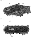
- FIG. 1 is a perspective view showing a sliding type glove box according to an embodiment of the present disclosure.
- FIG. 2 is a front view showing the sliding type glove box shown in FIG.1 .
- FIG. 3 is a perspective view showing a storage part in an ejected state from a housing according to the embodiment of the present disclosure.
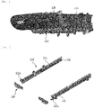
- FIG. 4 is a perspective view showing a structure of rails and stoppers according to the embodiment of the present disclosure.
- FIG. 5 is a perspective view showing a structure of each stopper shown in FIG. 4 .
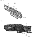
- FIG. 6 is a perspective view showing the storage part according to the embodiment of the present disclosure.
- FIG. 7 is a side view showing the storage part shown in FIG. 6 .
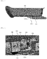
- FIG. 8 is an enlarged-perspective view showing area A shown in FIG. 3 .
- the sliding type glove box 100 includes: A housing 110 mounted to a dashboard (not shown); a pair of rails 120 provided inside the housing 110; a storage part 130 configured to be able to be ejected in a sliding manner while being moved along the rails 120.
- the housing 110 is a component mounted to the dashboard.
- the housing 110 has a space that may accommodate the storage part 130 therein.
- the rails 120 may be provided at the space provided inside the housing 110.
- the rails 120 may include: outer rails 121 mounted to the housing 110; and inner rails 122 configured to be movable along the outer rails and connected to a lower portion of the storage part 130.
- the pair of outer rails 121 mounted to the housing 110 may be disposed while being spaced apart from each other at a predetermined distance.
- the outer rails 121 according to the embodiment of the present disclosure is shown in the drawing as having a ' ⁇ '-shape.
- Each of the inner rails 122 may be provided in a groove portion formed in each of the outer rails 121 with having a length shorter than a length of the outer rails 121.
- the inner rails 122 may be moved in a longitudinal direction of the outer rail 121 while being connected to the lower portion of the storage part 130.
- the storage part 130 may be moved in the sliding manner.
- the outer rails 121 may include stoppers 200 that limit a moving distance of the storage part 130.
- the stoppers 200 may be provided on connection pieces 121a provided on a longitudinal end of each of the outer rails 121.
- the connection pieces 121a may be integrally formed with the outer rails 121, and each of the connection pieces 121a may be bent toward an inner lateral portion of the housing 110.
- Each of the stoppers 200 includes: a first coupling member 210 removably coupled to the connection piece 121a; a blocking member 220 integrally coupled to the first coupling member 210 and extended in a facing direction of the pair of the outer rails 121 to block the longitudinal end of the outer rail 121; and a second coupling member 230 integrally connected to the blocking member 220 and coupled to a lower-side front surface of the housing.
- the first coupling member 210 may be coupled to the connection piece 121a by using a known fastening means such as a bolt, a nut, and a screw. Therefore, both the first coupling member 210 and the connection piece 121a have fastening holes into which the fastening means may be inserted.
- a known fastening means such as a bolt, a nut, and a screw. Therefore, both the first coupling member 210 and the connection piece 121a have fastening holes into which the fastening means may be inserted.
- connection piece 121a is formed to be bent from the longitudinal end of the outer rail 121 toward the inner lateral portion of the housing 110 as described above.
- connection pieces 121a are exposed to the outside of the outer rails.
- the connection pieces 121a are formed on positions that do not interfere with the movement of the inner rails 122.
- connection pieces 121a are formed to be bent in the facing direction of the pair of outer rails 121, the operator should perform a bolting work of the first coupling member 210 and the connection pieces 121a with difficulty. Because the connection pieces 121a is not exposed to the naked eyes of the operator.
- connection piece 121a is formed to be bent from the longitudinal end of the outer rail 121 in the facing direction of the pair of outer rails 121, the inner rail 122 is prevented from being separated through the longitudinal end of the outer rail 121, whereby the operator cannot separate the storage part 130 from the housing 110.
- connection piece 121a may be formed to be bent from the longitudinal end of the outer rail 121 in the direction opposite to the facing direction of the pair of outer rails 121, that is, to be bent toward the lateral portion of the housing 110.
- the blocking member 220 serves to prevent the inner rail 122 from being separated from the groove portion of the outer rail 121, when the inner rail 122 is moved from a longitudinal second side to a longitudinal first side of the outer rail 121 for opening the storage part 130.
- the blocking member 220 serves to prevent the inner rail 122 from being separated from the outer rail 121, when the storage part 130 is ejected from the housing 110 and fully opened as shown in FIGS. 3 and 8 .
- the second coupling member 230 serves to reinforce a supporting force of the blocking member 220 by being coupled to a lower portion of the housing 110, as shown in FIGS. 3 and 8 .
- the second coupling member 230 may be coupled to a front surface of the lower portion of the housing 110 by a fastening means. Accordingly, the second coupling member 230 and the lower side front surface of the housing 110 have fastening holes, respectively, and the fastening means such as a bolt or a screw may be inserted into the fastening holes.
- the stopper 200 configured as described above may be separated from the longitudinal ends of the outer rail 121 by a releasing word of the fastening means, when the user needs to separate the storage part from the housing 110 for replacement or maintenance of the storage part 130.
- the storage part 130 may include a connection member 131 connected to the inner rail 122.
- the connection member 131 may be formed in a bar shape and a pair of connection members 131 may be provided on one side of the lower portion of the storage part 130 at a distance therebetween.
- the storage part 130 may be opened.
- the rails may not be exposed to the outside of the housing, even when the storage part 130 is exposed to the outside of the housing 110.
- connection member 131 may include a fixed pin 131a that is inserted into the movement prevention hole 221 formed in the blocking member 220.
- the fixed pin 131a and the movement prevention hole 221 formed in the blocking member 220 serve to prevent the storage part 130 from being moved due to an external impact or shaking.
- the longitudinal end of the inner rail 122 is brought into contact with a rear surface of the blocking member 220 of the stopper 200. Then, the fixed pin 131a formed on the front surface of the connection member 131 may be inserted into the movement prevention hole 221 formed on the blocking member 220 so that the storage part 130 is not moved in a transversal direction thereof.
- the storage part 130 remaining in the opening state may be prevented from being moved in the transversal direction thereof.
- the blocking member 220 of the stopper 200 serves to prevent the storage part 130 remaining in the opening state from being moved forward in a longitudinal direction of the first end, and the movement prevention hole 221 formed on the blocking member 220 and the fixed pin 131a formed on the connection member 131 prevents the storage part 130 in the opening state from being moved in the transversal direction.
- the stopper 200 limits a longitudinal direction of the storage part 130 and prevents the storage part 130 from being moved in the transversal direction when the storage part 130 is moved and opened from the housing 110.
- connection member 131 may have an buffer member 131b that is brought into contact with the rear surface of the blocking member 220 when the storage part 130 is moved in the sliding manner to be exposed to the outside of the housing 110.
- the buffer member 131b may be provided on the front surface of the connection member 131 while being located above a position in which the fixed pin 131a is formed.
- the buffer member 131b may have a protruding length that is in contact with the rear surface of the blocking member 220, when the fixed pin 131a is inserted into the movement prevention hole 221.
- the buffer member 131b may be manufactured of material having elasticity, such as a rubber material, silicone, a synthetic resin material.
Landscapes
- Engineering & Computer Science (AREA)
- Mechanical Engineering (AREA)
- Vehicle Step Arrangements And Article Storage (AREA)
- Casings For Electric Apparatus (AREA)
Applications Claiming Priority (1)
| Application Number | Priority Date | Filing Date | Title |
|---|---|---|---|
| KR1020200154663A KR102501242B1 (ko) | 2020-11-18 | 2020-11-18 | 슬라이딩형 글로브 박스 |
Publications (2)
| Publication Number | Publication Date |
|---|---|
| EP4001015A1 true EP4001015A1 (de) | 2022-05-25 |
| EP4001015B1 EP4001015B1 (de) | 2024-06-19 |
Family
ID=78617240
Family Applications (1)
| Application Number | Title | Priority Date | Filing Date |
|---|---|---|---|
| EP21207883.6A Active EP4001015B1 (de) | 2020-11-18 | 2021-11-12 | Verschiebbares handschuhfach |
Country Status (4)
| Country | Link |
|---|---|
| US (1) | US11718237B2 (de) |
| EP (1) | EP4001015B1 (de) |
| KR (1) | KR102501242B1 (de) |
| CN (1) | CN114537286B (de) |
Families Citing this family (1)
| Publication number | Priority date | Publication date | Assignee | Title |
|---|---|---|---|---|
| KR102530050B1 (ko) * | 2021-03-17 | 2023-05-08 | 케이비아이동국실업 주식회사 | 슬라이딩형 글로브 박스 |
Citations (3)
| Publication number | Priority date | Publication date | Assignee | Title |
|---|---|---|---|---|
| US20190135187A1 (en) * | 2017-11-06 | 2019-05-09 | Global Ip Holdings Llc | Assembly capable of deploying stowed items in a passenger compartment of a vehicle |
| KR102082171B1 (ko) | 2018-12-14 | 2020-02-27 | 케이비아이동국실업 주식회사 | 차량용 전동 슬라이딩 글로브박스의 작동장치 |
| EP3944990A1 (de) * | 2020-07-29 | 2022-02-02 | Hyundai Mobis Co., Ltd. | Rüttelschutzstruktur für handschuhfach |
Family Cites Families (32)
| Publication number | Priority date | Publication date | Assignee | Title |
|---|---|---|---|---|
| JPH0434389Y2 (de) * | 1984-12-17 | 1992-08-17 | ||
| JP2806835B2 (ja) * | 1995-08-30 | 1998-09-30 | セントラル自動車株式会社 | 補助シート |
| FR2760706B1 (fr) * | 1997-03-12 | 1999-04-30 | Reydel Sa | Dispositif de rangement pour habitacle interieur de vehicule, notamment vehicule automobile |
| KR100350274B1 (ko) | 2000-08-08 | 2002-08-28 | 기아자동차주식회사 | 자동차용 글로브박스 |
| KR100377153B1 (ko) * | 2000-12-19 | 2003-03-26 | 현대자동차주식회사 | 자동차의 글로브 박스 |
| JP3979316B2 (ja) * | 2002-03-19 | 2007-09-19 | トヨタ紡織株式会社 | 車両用物入れ装置 |
| US7165798B2 (en) * | 2004-02-06 | 2007-01-23 | Paccar Inc | Instrument mounting assembly |
| KR100693937B1 (ko) * | 2005-10-13 | 2007-03-12 | 정자훈 | 멀티미디어 기능 강의대용 커버개폐레일장치 |
| KR100698673B1 (ko) * | 2005-12-12 | 2007-03-23 | 현대모비스 주식회사 | 차량의 슬라이딩 트레이 |
| KR100868151B1 (ko) | 2007-10-04 | 2008-11-12 | 지엠대우오토앤테크놀로지주식회사 | 슬라이딩 도어를 갖는 차량용 글로브 박스 |
| DE102009012736A1 (de) * | 2009-03-11 | 2010-09-16 | GM Global Technology Operations, Inc., Detroit | Aufnahmevorrichtung |
| US20100244479A1 (en) * | 2009-03-25 | 2010-09-30 | International Truck Intellectual Property Company, Llc | Sliding bar assembly for use in cargo storage applications |
| JP5553664B2 (ja) * | 2010-03-31 | 2014-07-16 | カルソニックカンセイ株式会社 | 引き出し式物入れ |
| JP5621472B2 (ja) * | 2010-09-28 | 2014-11-12 | アイシン精機株式会社 | 車両用スライド装置、及びスライド装置用転動体循環ユニット |
| CN201872678U (zh) * | 2010-11-23 | 2011-06-22 | 上海延锋江森安亭座椅总成有限公司 | 汽车座椅储物盒装置 |
| JP5832797B2 (ja) * | 2011-07-05 | 2015-12-16 | 株式会社ニフコ | カップホルダ |
| DE102011118150A1 (de) * | 2011-11-10 | 2013-05-16 | Gm Global Technology Operations, Llc | Lagerung eines Funktionselements in einem Schienenpaar innerhalb eines Fahrgastraums eines Kraftfahrzeugs |
| DE102011118576B4 (de) * | 2011-11-15 | 2015-06-25 | Faurecia Innenraum Systeme Gmbh | Betätigungsvorrichtung |
| KR20140039883A (ko) * | 2012-09-25 | 2014-04-02 | 현대모비스 주식회사 | 렌즈 유닛 및 이를 이용한 차량용 램프 |
| DE102013204547B4 (de) * | 2013-03-15 | 2025-07-24 | Faurecia Innenraum Systeme Gmbh | Montageanordnung eines Handschuhfachs |
| CN203294034U (zh) * | 2013-05-21 | 2013-11-20 | 北汽福田汽车股份有限公司 | 一种蓄电池滑移固定装置 |
| JP5896477B2 (ja) * | 2013-07-31 | 2016-03-30 | 豊田合成株式会社 | グラブボックス |
| US9428092B2 (en) * | 2014-06-09 | 2016-08-30 | Honda Motor Co., Ltd. | Sliding and removable cup holder assembly for vehicle |
| CN204149945U (zh) * | 2014-09-24 | 2015-02-11 | 崔志刚 | 扶手箱通用盒体及扶手箱 |
| JP6420618B2 (ja) * | 2014-10-01 | 2018-11-07 | 株式会社パイオラックス | ロック解除装置およびそれを備えるロック装置 |
| CN104442589B (zh) * | 2014-12-18 | 2016-08-24 | 安徽江淮汽车股份有限公司 | 一种汽车的手套箱总成以及汽车 |
| US9914398B1 (en) * | 2017-03-09 | 2018-03-13 | Honda Motor Co., Ltd. | Vehicle storage compartment |
| CN107310485B (zh) * | 2017-07-13 | 2024-04-30 | 王冠文 | 一种具有滑轨结构的车载储物箱 |
| WO2020058143A1 (de) * | 2018-09-17 | 2020-03-26 | Motherson Innovations Company Ltd. | Mittelkonsole zwischen zwei fahrzeugsitzen und kraftfahrzeug mit solch einer mittelkonsole |
| KR102606594B1 (ko) * | 2018-10-25 | 2023-11-28 | 현대모비스 주식회사 | 글로브 박스 장치 |
| DE102018222852A1 (de) * | 2018-12-21 | 2020-06-25 | Brose Fahrzeugteile SE & Co. Kommanditgesellschaft, Coburg | Kraftfahrzeugbaugruppe mit einer Mittelkomponente |
| KR102390625B1 (ko) * | 2020-07-29 | 2022-04-26 | 케이비아이동국실업 주식회사 | 슬라이딩형 글로브 박스 |
-
2020
- 2020-11-18 KR KR1020200154663A patent/KR102501242B1/ko active Active
-
2021
- 2021-10-21 US US17/507,725 patent/US11718237B2/en active Active
- 2021-10-28 CN CN202111262114.XA patent/CN114537286B/zh active Active
- 2021-11-12 EP EP21207883.6A patent/EP4001015B1/de active Active
Patent Citations (3)
| Publication number | Priority date | Publication date | Assignee | Title |
|---|---|---|---|---|
| US20190135187A1 (en) * | 2017-11-06 | 2019-05-09 | Global Ip Holdings Llc | Assembly capable of deploying stowed items in a passenger compartment of a vehicle |
| KR102082171B1 (ko) | 2018-12-14 | 2020-02-27 | 케이비아이동국실업 주식회사 | 차량용 전동 슬라이딩 글로브박스의 작동장치 |
| EP3944990A1 (de) * | 2020-07-29 | 2022-02-02 | Hyundai Mobis Co., Ltd. | Rüttelschutzstruktur für handschuhfach |
Also Published As
| Publication number | Publication date |
|---|---|
| CN114537286B (zh) | 2024-05-03 |
| CN114537286A (zh) | 2022-05-27 |
| EP4001015B1 (de) | 2024-06-19 |
| US20220153203A1 (en) | 2022-05-19 |
| KR102501242B1 (ko) | 2023-02-16 |
| KR20220067899A (ko) | 2022-05-25 |
| US11718237B2 (en) | 2023-08-08 |
Similar Documents
| Publication | Publication Date | Title |
|---|---|---|
| KR100420768B1 (ko) | 글러브 컴파트먼트 | |
| KR102195056B1 (ko) | 차량의 내부 트림 상에 물체를 장착하기 위한 장치 및 차량 | |
| US10967808B2 (en) | Interior cover mount assembly | |
| EP4001015A1 (de) | Verschiebbares handschuhfach | |
| US7390054B2 (en) | Vehicle slide door apparatus | |
| KR102478817B1 (ko) | 착탈형 스톱퍼를 구비한 슬라이딩형 글로브 박스 | |
| CN112443228A (zh) | 具有可自调节止动件的缓冲装置 | |
| KR101614134B1 (ko) | 스토퍼 일체형 글로브박스 | |
| EP4309956A1 (de) | Handschuhfach vom schiebetyp | |
| JP5208557B2 (ja) | 自動車用デッキボードの高さ切替構造 | |
| KR102694529B1 (ko) | 엔진 지지대 및 샤시를 포함하는 자동차 | |
| US20140375039A1 (en) | Doors for console boxes | |
| CN112368183B (zh) | 用于机动车的后盖的饰衬元件、后盖以及机动车 | |
| EP2189315B1 (de) | Sonnenblendenvorrichtung für Fahrzeug | |
| JP2004525811A (ja) | バンパー構造を有する自動車の後部扉 | |
| KR200157250Y1 (ko) | 자동차용 루프 캐리어 | |
| JP2012224217A (ja) | フードステーホルダ | |
| CN108602471B (zh) | 车辆用内饰结构 | |
| KR102478810B1 (ko) | 멈춤 구조를 가지는 슬라이딩형 글로브 박스 | |
| KR100680713B1 (ko) | 차량용 글로브 박스 보강구조 | |
| KR101583635B1 (ko) | 수납장치 | |
| KR20110126423A (ko) | 자동차용 트레이의 커버 열림 방지 장치 | |
| JP6104783B2 (ja) | コンソールボックス | |
| KR20030013823A (ko) | 자동차용 콘솔 암레스트의 슬라이드 구조 | |
| KR100517697B1 (ko) | 글로브박스의 댐퍼구조 |
Legal Events
| Date | Code | Title | Description |
|---|---|---|---|
| PUAI | Public reference made under article 153(3) epc to a published international application that has entered the european phase |
Free format text: ORIGINAL CODE: 0009012 |
|
| STAA | Information on the status of an ep patent application or granted ep patent |
Free format text: STATUS: REQUEST FOR EXAMINATION WAS MADE |
|
| 17P | Request for examination filed |
Effective date: 20211112 |
|
| AK | Designated contracting states |
Kind code of ref document: A1 Designated state(s): AL AT BE BG CH CY CZ DE DK EE ES FI FR GB GR HR HU IE IS IT LI LT LU LV MC MK MT NL NO PL PT RO RS SE SI SK SM TR |
|
| RBV | Designated contracting states (corrected) |
Designated state(s): AL AT BE BG CH CY CZ DE DK EE ES FI FR GB GR HR HU IE IS IT LI LT LU LV MC MK MT NL NO PL PT RO RS SE SI SK SM TR |
|
| GRAP | Despatch of communication of intention to grant a patent |
Free format text: ORIGINAL CODE: EPIDOSNIGR1 |
|
| STAA | Information on the status of an ep patent application or granted ep patent |
Free format text: STATUS: GRANT OF PATENT IS INTENDED |
|
| INTG | Intention to grant announced |
Effective date: 20240123 |
|
| GRAS | Grant fee paid |
Free format text: ORIGINAL CODE: EPIDOSNIGR3 |
|
| GRAA | (expected) grant |
Free format text: ORIGINAL CODE: 0009210 |
|
| STAA | Information on the status of an ep patent application or granted ep patent |
Free format text: STATUS: THE PATENT HAS BEEN GRANTED |
|
| P01 | Opt-out of the competence of the unified patent court (upc) registered |
Effective date: 20240506 |
|
| AK | Designated contracting states |
Kind code of ref document: B1 Designated state(s): AL AT BE BG CH CY CZ DE DK EE ES FI FR GB GR HR HU IE IS IT LI LT LU LV MC MK MT NL NO PL PT RO RS SE SI SK SM TR |
|
| REG | Reference to a national code |
Ref country code: GB Ref legal event code: FG4D |
|
| REG | Reference to a national code |
Ref country code: CH Ref legal event code: EP |
|
| REG | Reference to a national code |
Ref country code: DE Ref legal event code: R096 Ref document number: 602021014545 Country of ref document: DE |
|
| PG25 | Lapsed in a contracting state [announced via postgrant information from national office to epo] |
Ref country code: BG Free format text: LAPSE BECAUSE OF FAILURE TO SUBMIT A TRANSLATION OF THE DESCRIPTION OR TO PAY THE FEE WITHIN THE PRESCRIBED TIME-LIMIT Effective date: 20240619 |
|
| PG25 | Lapsed in a contracting state [announced via postgrant information from national office to epo] |
Ref country code: FI Free format text: LAPSE BECAUSE OF FAILURE TO SUBMIT A TRANSLATION OF THE DESCRIPTION OR TO PAY THE FEE WITHIN THE PRESCRIBED TIME-LIMIT Effective date: 20240619 Ref country code: HR Free format text: LAPSE BECAUSE OF FAILURE TO SUBMIT A TRANSLATION OF THE DESCRIPTION OR TO PAY THE FEE WITHIN THE PRESCRIBED TIME-LIMIT Effective date: 20240619 |
|
| REG | Reference to a national code |
Ref country code: LT Ref legal event code: MG9D |
|
| PG25 | Lapsed in a contracting state [announced via postgrant information from national office to epo] |
Ref country code: GR Free format text: LAPSE BECAUSE OF FAILURE TO SUBMIT A TRANSLATION OF THE DESCRIPTION OR TO PAY THE FEE WITHIN THE PRESCRIBED TIME-LIMIT Effective date: 20240920 |
|
| REG | Reference to a national code |
Ref country code: NL Ref legal event code: MP Effective date: 20240619 |
|
| PG25 | Lapsed in a contracting state [announced via postgrant information from national office to epo] |
Ref country code: LV Free format text: LAPSE BECAUSE OF FAILURE TO SUBMIT A TRANSLATION OF THE DESCRIPTION OR TO PAY THE FEE WITHIN THE PRESCRIBED TIME-LIMIT Effective date: 20240619 |
|
| PG25 | Lapsed in a contracting state [announced via postgrant information from national office to epo] |
Ref country code: NO Free format text: LAPSE BECAUSE OF FAILURE TO SUBMIT A TRANSLATION OF THE DESCRIPTION OR TO PAY THE FEE WITHIN THE PRESCRIBED TIME-LIMIT Effective date: 20240919 Ref country code: LV Free format text: LAPSE BECAUSE OF FAILURE TO SUBMIT A TRANSLATION OF THE DESCRIPTION OR TO PAY THE FEE WITHIN THE PRESCRIBED TIME-LIMIT Effective date: 20240619 Ref country code: HR Free format text: LAPSE BECAUSE OF FAILURE TO SUBMIT A TRANSLATION OF THE DESCRIPTION OR TO PAY THE FEE WITHIN THE PRESCRIBED TIME-LIMIT Effective date: 20240619 Ref country code: GR Free format text: LAPSE BECAUSE OF FAILURE TO SUBMIT A TRANSLATION OF THE DESCRIPTION OR TO PAY THE FEE WITHIN THE PRESCRIBED TIME-LIMIT Effective date: 20240920 Ref country code: FI Free format text: LAPSE BECAUSE OF FAILURE TO SUBMIT A TRANSLATION OF THE DESCRIPTION OR TO PAY THE FEE WITHIN THE PRESCRIBED TIME-LIMIT Effective date: 20240619 Ref country code: BG Free format text: LAPSE BECAUSE OF FAILURE TO SUBMIT A TRANSLATION OF THE DESCRIPTION OR TO PAY THE FEE WITHIN THE PRESCRIBED TIME-LIMIT Effective date: 20240619 Ref country code: RS Free format text: LAPSE BECAUSE OF FAILURE TO SUBMIT A TRANSLATION OF THE DESCRIPTION OR TO PAY THE FEE WITHIN THE PRESCRIBED TIME-LIMIT Effective date: 20240919 |
|
| PG25 | Lapsed in a contracting state [announced via postgrant information from national office to epo] |
Ref country code: NL Free format text: LAPSE BECAUSE OF FAILURE TO SUBMIT A TRANSLATION OF THE DESCRIPTION OR TO PAY THE FEE WITHIN THE PRESCRIBED TIME-LIMIT Effective date: 20240619 |
|
| REG | Reference to a national code |
Ref country code: AT Ref legal event code: MK05 Ref document number: 1695737 Country of ref document: AT Kind code of ref document: T Effective date: 20240619 |
|
| PG25 | Lapsed in a contracting state [announced via postgrant information from national office to epo] |
Ref country code: NL Free format text: LAPSE BECAUSE OF FAILURE TO SUBMIT A TRANSLATION OF THE DESCRIPTION OR TO PAY THE FEE WITHIN THE PRESCRIBED TIME-LIMIT Effective date: 20240619 |
|
| PG25 | Lapsed in a contracting state [announced via postgrant information from national office to epo] |
Ref country code: PT Free format text: LAPSE BECAUSE OF FAILURE TO SUBMIT A TRANSLATION OF THE DESCRIPTION OR TO PAY THE FEE WITHIN THE PRESCRIBED TIME-LIMIT Effective date: 20241021 |
|
| PG25 | Lapsed in a contracting state [announced via postgrant information from national office to epo] |
Ref country code: PT Free format text: LAPSE BECAUSE OF FAILURE TO SUBMIT A TRANSLATION OF THE DESCRIPTION OR TO PAY THE FEE WITHIN THE PRESCRIBED TIME-LIMIT Effective date: 20241021 |
|
| PG25 | Lapsed in a contracting state [announced via postgrant information from national office to epo] |
Ref country code: PL Free format text: LAPSE BECAUSE OF FAILURE TO SUBMIT A TRANSLATION OF THE DESCRIPTION OR TO PAY THE FEE WITHIN THE PRESCRIBED TIME-LIMIT Effective date: 20240619 |
|
| PG25 | Lapsed in a contracting state [announced via postgrant information from national office to epo] |
Ref country code: EE Free format text: LAPSE BECAUSE OF FAILURE TO SUBMIT A TRANSLATION OF THE DESCRIPTION OR TO PAY THE FEE WITHIN THE PRESCRIBED TIME-LIMIT Effective date: 20240619 |
|
| PG25 | Lapsed in a contracting state [announced via postgrant information from national office to epo] |
Ref country code: IS Free format text: LAPSE BECAUSE OF FAILURE TO SUBMIT A TRANSLATION OF THE DESCRIPTION OR TO PAY THE FEE WITHIN THE PRESCRIBED TIME-LIMIT Effective date: 20241019 Ref country code: AT Free format text: LAPSE BECAUSE OF FAILURE TO SUBMIT A TRANSLATION OF THE DESCRIPTION OR TO PAY THE FEE WITHIN THE PRESCRIBED TIME-LIMIT Effective date: 20240619 |
|
| PG25 | Lapsed in a contracting state [announced via postgrant information from national office to epo] |
Ref country code: CZ Free format text: LAPSE BECAUSE OF FAILURE TO SUBMIT A TRANSLATION OF THE DESCRIPTION OR TO PAY THE FEE WITHIN THE PRESCRIBED TIME-LIMIT Effective date: 20240619 |
|
| PG25 | Lapsed in a contracting state [announced via postgrant information from national office to epo] |
Ref country code: RO Free format text: LAPSE BECAUSE OF FAILURE TO SUBMIT A TRANSLATION OF THE DESCRIPTION OR TO PAY THE FEE WITHIN THE PRESCRIBED TIME-LIMIT Effective date: 20240619 Ref country code: SK Free format text: LAPSE BECAUSE OF FAILURE TO SUBMIT A TRANSLATION OF THE DESCRIPTION OR TO PAY THE FEE WITHIN THE PRESCRIBED TIME-LIMIT Effective date: 20240619 |
|
| PG25 | Lapsed in a contracting state [announced via postgrant information from national office to epo] |
Ref country code: SM Free format text: LAPSE BECAUSE OF FAILURE TO SUBMIT A TRANSLATION OF THE DESCRIPTION OR TO PAY THE FEE WITHIN THE PRESCRIBED TIME-LIMIT Effective date: 20240619 Ref country code: ES Free format text: LAPSE BECAUSE OF FAILURE TO SUBMIT A TRANSLATION OF THE DESCRIPTION OR TO PAY THE FEE WITHIN THE PRESCRIBED TIME-LIMIT Effective date: 20240619 |
|
| PG25 | Lapsed in a contracting state [announced via postgrant information from national office to epo] |
Ref country code: SM Free format text: LAPSE BECAUSE OF FAILURE TO SUBMIT A TRANSLATION OF THE DESCRIPTION OR TO PAY THE FEE WITHIN THE PRESCRIBED TIME-LIMIT Effective date: 20240619 Ref country code: SK Free format text: LAPSE BECAUSE OF FAILURE TO SUBMIT A TRANSLATION OF THE DESCRIPTION OR TO PAY THE FEE WITHIN THE PRESCRIBED TIME-LIMIT Effective date: 20240619 Ref country code: RO Free format text: LAPSE BECAUSE OF FAILURE TO SUBMIT A TRANSLATION OF THE DESCRIPTION OR TO PAY THE FEE WITHIN THE PRESCRIBED TIME-LIMIT Effective date: 20240619 Ref country code: PL Free format text: LAPSE BECAUSE OF FAILURE TO SUBMIT A TRANSLATION OF THE DESCRIPTION OR TO PAY THE FEE WITHIN THE PRESCRIBED TIME-LIMIT Effective date: 20240619 Ref country code: IS Free format text: LAPSE BECAUSE OF FAILURE TO SUBMIT A TRANSLATION OF THE DESCRIPTION OR TO PAY THE FEE WITHIN THE PRESCRIBED TIME-LIMIT Effective date: 20241019 Ref country code: ES Free format text: LAPSE BECAUSE OF FAILURE TO SUBMIT A TRANSLATION OF THE DESCRIPTION OR TO PAY THE FEE WITHIN THE PRESCRIBED TIME-LIMIT Effective date: 20240619 Ref country code: EE Free format text: LAPSE BECAUSE OF FAILURE TO SUBMIT A TRANSLATION OF THE DESCRIPTION OR TO PAY THE FEE WITHIN THE PRESCRIBED TIME-LIMIT Effective date: 20240619 Ref country code: CZ Free format text: LAPSE BECAUSE OF FAILURE TO SUBMIT A TRANSLATION OF THE DESCRIPTION OR TO PAY THE FEE WITHIN THE PRESCRIBED TIME-LIMIT Effective date: 20240619 Ref country code: AT Free format text: LAPSE BECAUSE OF FAILURE TO SUBMIT A TRANSLATION OF THE DESCRIPTION OR TO PAY THE FEE WITHIN THE PRESCRIBED TIME-LIMIT Effective date: 20240619 |
|
| PG25 | Lapsed in a contracting state [announced via postgrant information from national office to epo] |
Ref country code: IT Free format text: LAPSE BECAUSE OF FAILURE TO SUBMIT A TRANSLATION OF THE DESCRIPTION OR TO PAY THE FEE WITHIN THE PRESCRIBED TIME-LIMIT Effective date: 20240619 |
|
| REG | Reference to a national code |
Ref country code: DE Ref legal event code: R097 Ref document number: 602021014545 Country of ref document: DE |
|
| PG25 | Lapsed in a contracting state [announced via postgrant information from national office to epo] |
Ref country code: DK Free format text: LAPSE BECAUSE OF FAILURE TO SUBMIT A TRANSLATION OF THE DESCRIPTION OR TO PAY THE FEE WITHIN THE PRESCRIBED TIME-LIMIT Effective date: 20240619 |
|
| PLBE | No opposition filed within time limit |
Free format text: ORIGINAL CODE: 0009261 |
|
| STAA | Information on the status of an ep patent application or granted ep patent |
Free format text: STATUS: NO OPPOSITION FILED WITHIN TIME LIMIT |
|
| 26N | No opposition filed |
Effective date: 20250320 |
|
| REG | Reference to a national code |
Ref country code: CH Ref legal event code: PL |
|
| PG25 | Lapsed in a contracting state [announced via postgrant information from national office to epo] |
Ref country code: MC Free format text: LAPSE BECAUSE OF FAILURE TO SUBMIT A TRANSLATION OF THE DESCRIPTION OR TO PAY THE FEE WITHIN THE PRESCRIBED TIME-LIMIT Effective date: 20240619 |
|
| PG25 | Lapsed in a contracting state [announced via postgrant information from national office to epo] |
Ref country code: LU Free format text: LAPSE BECAUSE OF NON-PAYMENT OF DUE FEES Effective date: 20241112 |
|
| REG | Reference to a national code |
Ref country code: CH Ref legal event code: PL |
|
| PG25 | Lapsed in a contracting state [announced via postgrant information from national office to epo] |
Ref country code: CH Free format text: LAPSE BECAUSE OF NON-PAYMENT OF DUE FEES Effective date: 20241130 |
|
| REG | Reference to a national code |
Ref country code: BE Ref legal event code: MM Effective date: 20241130 |
|
| PG25 | Lapsed in a contracting state [announced via postgrant information from national office to epo] |
Ref country code: SE Free format text: LAPSE BECAUSE OF FAILURE TO SUBMIT A TRANSLATION OF THE DESCRIPTION OR TO PAY THE FEE WITHIN THE PRESCRIBED TIME-LIMIT Effective date: 20240619 |
|
| PG25 | Lapsed in a contracting state [announced via postgrant information from national office to epo] |
Ref country code: BE Free format text: LAPSE BECAUSE OF NON-PAYMENT OF DUE FEES Effective date: 20241130 |
|
| PG25 | Lapsed in a contracting state [announced via postgrant information from national office to epo] |
Ref country code: IE Free format text: LAPSE BECAUSE OF NON-PAYMENT OF DUE FEES Effective date: 20241112 |
|
| PGFP | Annual fee paid to national office [announced via postgrant information from national office to epo] |
Ref country code: DE Payment date: 20251128 Year of fee payment: 5 |
|
| PGFP | Annual fee paid to national office [announced via postgrant information from national office to epo] |
Ref country code: GB Payment date: 20251120 Year of fee payment: 5 |
|
| PGFP | Annual fee paid to national office [announced via postgrant information from national office to epo] |
Ref country code: FR Payment date: 20251125 Year of fee payment: 5 |
|
| PG25 | Lapsed in a contracting state [announced via postgrant information from national office to epo] |
Ref country code: HU Free format text: LAPSE BECAUSE OF FAILURE TO SUBMIT A TRANSLATION OF THE DESCRIPTION OR TO PAY THE FEE WITHIN THE PRESCRIBED TIME-LIMIT; INVALID AB INITIO Effective date: 20211112 |