EP4001022B1 - Agencement de pare-chocs - Google Patents
Agencement de pare-chocs Download PDFInfo
- Publication number
- EP4001022B1 EP4001022B1 EP21207402.5A EP21207402A EP4001022B1 EP 4001022 B1 EP4001022 B1 EP 4001022B1 EP 21207402 A EP21207402 A EP 21207402A EP 4001022 B1 EP4001022 B1 EP 4001022B1
- Authority
- EP
- European Patent Office
- Prior art keywords
- cross
- motor vehicle
- bumper arrangement
- cross member
- shaped
- Prior art date
- Legal status (The legal status is an assumption and is not a legal conclusion. Google has not performed a legal analysis and makes no representation as to the accuracy of the status listed.)
- Active
Links
Images


Classifications
-
- B—PERFORMING OPERATIONS; TRANSPORTING
- B60—VEHICLES IN GENERAL
- B60R—VEHICLES, VEHICLE FITTINGS, OR VEHICLE PARTS, NOT OTHERWISE PROVIDED FOR
- B60R19/00—Wheel guards; Radiator guards, e.g. grilles; Obstruction removers; Fittings damping bouncing force in collisions
- B60R19/02—Bumpers, i.e. impact receiving or absorbing members for protecting vehicles or fending off blows from other vehicles or objects
- B60R19/04—Bumpers, i.e. impact receiving or absorbing members for protecting vehicles or fending off blows from other vehicles or objects formed from more than one section in a side-by-side arrangement
- B60R19/12—Bumpers, i.e. impact receiving or absorbing members for protecting vehicles or fending off blows from other vehicles or objects formed from more than one section in a side-by-side arrangement vertically spaced
-
- B—PERFORMING OPERATIONS; TRANSPORTING
- B60—VEHICLES IN GENERAL
- B60R—VEHICLES, VEHICLE FITTINGS, OR VEHICLE PARTS, NOT OTHERWISE PROVIDED FOR
- B60R19/00—Wheel guards; Radiator guards, e.g. grilles; Obstruction removers; Fittings damping bouncing force in collisions
- B60R19/02—Bumpers, i.e. impact receiving or absorbing members for protecting vehicles or fending off blows from other vehicles or objects
- B60R19/24—Arrangements for mounting bumpers on vehicles
- B60R19/26—Arrangements for mounting bumpers on vehicles comprising yieldable mounting means
- B60R19/34—Arrangements for mounting bumpers on vehicles comprising yieldable mounting means destroyed upon impact, e.g. one-shot type
-
- B—PERFORMING OPERATIONS; TRANSPORTING
- B60—VEHICLES IN GENERAL
- B60R—VEHICLES, VEHICLE FITTINGS, OR VEHICLE PARTS, NOT OTHERWISE PROVIDED FOR
- B60R19/00—Wheel guards; Radiator guards, e.g. grilles; Obstruction removers; Fittings damping bouncing force in collisions
- B60R19/02—Bumpers, i.e. impact receiving or absorbing members for protecting vehicles or fending off blows from other vehicles or objects
- B60R19/18—Bumpers, i.e. impact receiving or absorbing members for protecting vehicles or fending off blows from other vehicles or objects characterised by the cross-section; Means within the bumper to absorb impact
-
- B—PERFORMING OPERATIONS; TRANSPORTING
- B60—VEHICLES IN GENERAL
- B60R—VEHICLES, VEHICLE FITTINGS, OR VEHICLE PARTS, NOT OTHERWISE PROVIDED FOR
- B60R19/00—Wheel guards; Radiator guards, e.g. grilles; Obstruction removers; Fittings damping bouncing force in collisions
- B60R19/02—Bumpers, i.e. impact receiving or absorbing members for protecting vehicles or fending off blows from other vehicles or objects
- B60R19/18—Bumpers, i.e. impact receiving or absorbing members for protecting vehicles or fending off blows from other vehicles or objects characterised by the cross-section; Means within the bumper to absorb impact
- B60R2019/1806—Structural beams therefor, e.g. shock-absorbing
-
- B—PERFORMING OPERATIONS; TRANSPORTING
- B60—VEHICLES IN GENERAL
- B60R—VEHICLES, VEHICLE FITTINGS, OR VEHICLE PARTS, NOT OTHERWISE PROVIDED FOR
- B60R19/00—Wheel guards; Radiator guards, e.g. grilles; Obstruction removers; Fittings damping bouncing force in collisions
- B60R19/02—Bumpers, i.e. impact receiving or absorbing members for protecting vehicles or fending off blows from other vehicles or objects
- B60R19/18—Bumpers, i.e. impact receiving or absorbing members for protecting vehicles or fending off blows from other vehicles or objects characterised by the cross-section; Means within the bumper to absorb impact
- B60R2019/1806—Structural beams therefor, e.g. shock-absorbing
- B60R2019/1813—Structural beams therefor, e.g. shock-absorbing made of metal
-
- B—PERFORMING OPERATIONS; TRANSPORTING
- B60—VEHICLES IN GENERAL
- B60R—VEHICLES, VEHICLE FITTINGS, OR VEHICLE PARTS, NOT OTHERWISE PROVIDED FOR
- B60R19/00—Wheel guards; Radiator guards, e.g. grilles; Obstruction removers; Fittings damping bouncing force in collisions
- B60R19/02—Bumpers, i.e. impact receiving or absorbing members for protecting vehicles or fending off blows from other vehicles or objects
- B60R19/18—Bumpers, i.e. impact receiving or absorbing members for protecting vehicles or fending off blows from other vehicles or objects characterised by the cross-section; Means within the bumper to absorb impact
- B60R2019/1806—Structural beams therefor, e.g. shock-absorbing
- B60R2019/1813—Structural beams therefor, e.g. shock-absorbing made of metal
- B60R2019/1826—Structural beams therefor, e.g. shock-absorbing made of metal of high-tension steel
Definitions
- the present invention relates to a bumper arrangement for arrangement on a motor vehicle according to the features in the preamble of claim 1.
- a second task which is fulfilled by a bumper arrangement, is the conversion of crash energy into deformation processing and thereby a corresponding reduction in impact energy.
- a respective cross member is coupled to the motor vehicle via crash boxes.
- the crash boxes are on the Relative to the transverse direction of the vehicle, arranged between a central region and an end region of the cross member, therefore based on the vehicle width, each arranged between a third and a quarter with the length in the outer region of the cross member.
- the crash boxes are then usually coupled to the side members of the motor vehicle. In the event of an impact, the crash boxes fold like an accordion, converting crash energy into forming work.
- a bumper support according to the preamble of claim 1 is known for a vehicle which has an outer shell with passages.
- the object of the present invention is to provide a bumper arrangement which, in the event of penetration by an impacting object or motor vehicle, brings about an equalization and reduces peaks both in the vehicle itself and in a barrier.
- the present invention includes a bumper assembly for a motor vehicle.
- a cross member essentially extends over a large part of the width of the motor vehicle.
- Such a cross member is mounted in the front or rear area of the motor vehicle.
- the cross member itself is coupled to the motor vehicle via crash boxes. In particular, this takes place on the respective end sides of longitudinal members on the motor vehicle.
- the cross member itself is designed as a one-piece press-formed component made from the same material. This has a hat shape, in particular in cross section, and therefore a hat-shaped cross section.
- the component is made in particular from a high-strength steel with a tensile strength of more than 1200 MPa, in particular more than 1300 MPa.
- the cross member is particularly preferably produced as a hot-formed and press-hardened component.
- the cross member is characterized in that it is preferably designed to run obliquely downwards in a respective end region in the transverse direction of the motor vehicle, based on the vertical direction of the motor vehicle.
- the end area is ring-shaped. Ring-shaped does not necessarily mean round in the form of a circular ring. It can also be a square ring shape. However, this does not rule out the possibility that, according to the invention, the end region, ie an external part of the ring-shaped arrangement, is also optionally formed running obliquely downwards.
- This measure according to the invention ensures that the cross member itself is mounted so high that, for example in a bump-to-bumper test, it achieves sufficient overlap with another cross member of a colliding vehicle in relation to the motor vehicle vertical direction. At the same time, however, it is ensured that the end area, in the event of a deformation in the longitudinal direction of the motor vehicle, strikes a wheel house or wheel located behind it and is additionally supported here. A further moment of resistance in the longitudinal direction of the motor vehicle thus takes place via the wheel or the wheel suspension itself. In the event of a high-intensity crash, the wheel would be supported on the rocker panel, which in turn is located behind the wheel in the longitudinal direction of the vehicle.
- the diagonally downward running of the cross member ensures that the cross member hits the wheel located behind it as centrally as possible or is supported on the wheel in such a way that, in relation to the vertical direction, it engages below the wheel and thus just enables jacking up or upward sliding is prevented.
- the cross section of the cross member is hat-shaped.
- the cross section of the cross member is also largely profiled in the ring-shaped area, in particular U-shaped, particularly preferably hat-shaped.
- the cross member thus has a high deformation resistance in the longitudinal direction of the motor vehicle.
- the cross member itself can also be designed in the shape of a double hat in cross section.
- the opening of the hat shape is oriented in relation to the longitudinal direction, pointing forwards or pointing away from the motor vehicle. According to the invention, this offers the advantage that when deformed in the direction of the wheelhouse, the back of the hat shape, in particular with a rounded contour, strikes the wheel located behind it. Destruction of the tire is thereby reliably avoided.
- the ring-shaped area is arranged pointing downwards or offset downwards in the vertical direction of the motor vehicle in relation to the actual part of the cross member.
- an upper side of the annular area is an integral part of the cross member.
- the ring-shaped area has a recess in particular in its center.
- the actual end area or the outer end of the cross member is widened in its cross section. This also offers a larger support surface on the wheelhouse or tires behind it.
- a larger cross-sectional area is provided by the ring shape itself.
- Widened in cross-section can also mean that the cross-sectional width or cross-sectional height itself is designed to be larger than a middle section, ie is designed to be wider, and more cross-sectional area is therefore available as a result of this widening. This would then be in addition to the increase in cross section due to the ring shape.
- a larger impact area is provided overall, especially compared to a conventional, simple cross member, without ring shape.
- a downwardly extending part of the annular area is arranged below a connection of a crash box. This achieves better support in the event of a laterally offset impact.
- auxiliary cross member is particularly preferably arranged in a substantially parallel offset manner below the actual cross member.
- a second pair of crash boxes or side members can be arranged in the vertical direction of the motor vehicle below the aforementioned crash boxes, with these further crash boxes forming another lower load path and being fastened in the lower part of the end region of the cross member.
- the cross member itself has a profile that is curved in an arc around the vertical axis of the motor vehicle.
- the end areas are provided with a greater curvature in relation to a middle area.
- figure 1 shows a bumper arrangement 1 according to the invention from the front.
- a cross member 2 can be seen, which essentially extends over the width of a motor vehicle located behind it, which is not shown in detail.
- the cross member 2 is coupled to the motor vehicle with the incorporation of crash boxes 3 .
- a multi-part locking plate 4 (4.1, 4.2, 4.3) is arranged on the front side of the cross member 2.
- the cross member 2 is characterized in that it has a ring-shaped section in a respective end region 5 .
- Annular means a substantially square annular section.
- a part of the end portion 6 of the cross member 2 is formed sloping downward in the vertical direction Z of the motor vehicle.
- FIG 2 shows a perspective view of the bumper assembly 1 from behind. It can be seen here that the cross member 2 itself is designed in one piece and made of the same material.
- the cross member 2 has a hat-shaped profile cross section 8 .
- the hat-shaped profile cross-section 8 is also formed in each case in the ring-shaped end area 5 over the entire ring shape.
- the annular section in the end area 5 is formed in the vertical direction Z of the motor vehicle below the actual cross member 2 itself.
- the section 6 itself is arranged to run obliquely downwards in the vertical direction Z of the motor vehicle.
- a middle section 13 is also present.
- figure 3 shows a rear view of the cross member 2, which is also shown again in the outer end region 5 of the section 6 running obliquely downwards. Furthermore, in relation to the vertical direction Z of the motor vehicle, the annular section is formed below the actual main cross member.
- a downwardly oriented part 7 of the ring-shaped section is arranged below a connection area of a crash box 3 .
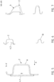
- FIG. 12 show different cross-sectional views according to section lines IV-IV to VII-VII figure 2 .
- FIG. 13 shows a corresponding cross-sectional view of section line IV-IV figure 2 .
- the crash box 3 can be seen here, as well as the hat-shaped profile 8 of the cross member 2, which is designed to the rear.
- An opening 9 is arranged oriented towards the front in the longitudinal direction X of the motor vehicle.
- the opening 9 is closed by a locking plate 4 here.
- the locking plate 4 extends not only over the opening 9, but also over a part 7 of the crossbeam 2 or of the annular end section which is oriented downwards.
- a lower part 10 of the annular end area 5 also has a hat-shaped profile.
- the cross member 2 itself has according to figure 5
- Section line VV has a hat-shaped profile 8 and the centrally arranged locking plate 4.
- the opening 9 is designed to be oriented forwards in the longitudinal direction X of the motor vehicle.
- the lower part and the upper part of the cross member are each designed in the shape of a hat.
- the locking plate 4 can have recesses, for example to save weight and/or to connect a towing eye, not shown in detail.
- section line VII-VII is shown.
- the sloping downward part is formed.
- the cross-sectional area of the cross member 2 is increased in this area.
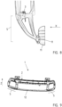
- FIG 9 shows a further embodiment variant of the bumper arrangement 1 according to the invention.
- an auxiliary cross member 12 is arranged, which is formed below the actual cross member 2 in relation to the vertical direction Z of the motor vehicle.
- This auxiliary cross member 12 connects the two ring-shaped end regions 5 to one another.
- the cross member 2 itself, but exclusively or auxiliary cross member 12 is formed from a steel material, in particular from a hot-workable and press-hardenable steel.
- the number of components can be reduced, particularly taking into account the locking plate 4, while at the same time the crash performance can be significantly increased, with a reduced dead weight of the entire bumper arrangement 1.
- Coated or uncoated material can be used particularly preferably.
- Each compression-moulded component, and therefore the crossbeam 2 or the locking plates 4, and also the auxiliary crossbeam 12 are preferably made of a material of the same thickness, and therefore a uniform material thickness for themselves. Strike plate 4, cross member 4 and auxiliary cross member 12 can, however, have different material thicknesses.
- the dead weight can also be reduced efficiently through the targeted use of materials, while at the same time the rigidity and crash performance can be increased.
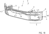
- figure 10 shows an alternative embodiment variant of a bumper arrangement 1 according to the invention.
- a region 15 is shown which is formed downwards in the vertical direction Z of the motor vehicle. The crash requirement of a bumper-to-bumper test is met by this offset or area 15 formed downwards.
- An annular area is formed in each of the outer end areas 5 .
- auxiliary cross member is arranged.
- the ring-shaped area is also oriented downwards in the vertical direction Z of the motor vehicle, in relation to the cross member 2 itself.
- the locking plates 4 (4.1, 4.2, 4.3) have openings at the front.
- the ring-shaped area in the respective end section of the cross member 2 itself is offset downwards in the vertical direction Z of the motor vehicle.
- the upper part of the annular area 15 is arranged at the level of the cross member 2 .
- the adjoining annular area is arranged so that it is oriented downwards in the vertical direction Z of the motor vehicle.
- the cross section 2 in the annular region 15 of the actual cross member 2 which in turn is produced as a uniform, one-piece press-formed part, is itself profiled. In the simplest case, this is a U-shaped profile. Particularly preferably, the hat-shaped cross section of the cross member also continues here in the entire ring-shaped area. This achieves a high level of rigidity.
- the overall height H5 of the end section is at least 50%, preferably 100% and very particularly preferably 150% greater than the height H of the cross member itself.
- the height H is more than 90 mm, in particular greater than 100 mm.
- the height H5 in the ring-shaped area is particularly preferably between 200 mm and 400 mm.
Landscapes
- Engineering & Computer Science (AREA)
- Mechanical Engineering (AREA)
- Body Structure For Vehicles (AREA)
- Vibration Dampers (AREA)
- Fittings On The Vehicle Exterior For Carrying Loads, And Devices For Holding Or Mounting Articles (AREA)
Claims (9)
- Agencement de pare-chocs (1) pour un véhicule automobile, présentant une traverse (2) qui peut être couplée par le biais de caissons de protection contre les chocs (3) au véhicule automobile et est fabriquée comme composant formé à la presse d'un seul tenant en un matériau homogène, dans lequella zone d'extrémité (5) est réalisée en anneau, caractérisé en ce quela forme annulaire est agencée orientée vers le bas par rapport à la traverse (2) dans le sens vertical du véhicule automobile (Z) de telle manière qu'une partie s'étendant orientée vers le bas de la zone annulaire soit agencée en dessous d'une liaison du caisson de protection contre les chocs.
- Agencement de pare-chocs (1) selon la revendication 1,
caractérisé en ce que la section transversale de la traverse (2) est réalisée en forme de chapeau, dans lequel l'ouverture (9) de la forme de chapeau est agencée tournée vers l'avant par rapport au sens longitudinal du véhicule automobile (X). - Agencement de pare-chocs selon la revendication 1 ou 2,
caractérisé en ce que la traverse est réalisée s'étendant orientée en biais vers le bas par rapport au sens vertical du véhicule automobile (Z) dans une zone d'extrémité (5) respective. - Agencement de pare-chocs (1) selon l'une quelconque des revendications précédentes,
caractérisé en ce que la zone annulaire est réalisée autoprofilée en section transversale, en particulier en forme de U, le plus préférentiellement en forme de chapeau. - Agencement de pare-chocs (1) selon l'une quelconque des revendications précédentes,
caractérisé en ce que la zone d'extrémité (5) est réalisée élargie dans son aire de section. - Agencement de pare-chocs (1) selon l'une quelconque des revendications précédentes,
caractérisé en ce que des zones annulaires agencées sur des côtés opposés sont reliées entre elles par une traverse auxiliaire (12), dans lequel la traverse auxiliaire (12) est agencée en dessous de la traverse (2). - Agencement de pare-chocs (1) selon l'une quelconque des revendications précédentes,
caractérisé en ce qu'une tôle de fermeture (4) est agencée au moins par section longitudinale qui ferme au moins partiellement en particulier l'ouverture (9) de la forme de chapeau. - Agencement de pare-chocs (1) selon l'une quelconque des revendications précédentes,
caractérisé en ce qu'un côté extérieur de la zone d'extrémité (5) est agencé dans l'état de montage par rapport au sens transversal du véhicule automobile avant une surface de roue de telle manière qu'en cas de déformation de la traverse (2) dans le sens longitudinal du véhicule automobile (X), un côté arrière de la traverse (2) s'appuie contre un passage de roue et/ou une surface de roue d'une roue (11). - Agencement de pare-chocs (1) selon l'une quelconque des revendications précédentes,
caractérisé en ce que la traverse (2) présente en vue en élévation autour de l'axe vertical de véhicule automobile une étendue incurvée, dans lequel en particulier les zones d'extrémité (5) présentent une courbure arquée ou sont réalisées coudées par rapport à la section médiane (13).
Applications Claiming Priority (1)
| Application Number | Priority Date | Filing Date | Title |
|---|---|---|---|
| DE102020130039.5A DE102020130039B3 (de) | 2020-11-13 | 2020-11-13 | Stoßfängeranordnung |
Publications (2)
| Publication Number | Publication Date |
|---|---|
| EP4001022A1 EP4001022A1 (fr) | 2022-05-25 |
| EP4001022B1 true EP4001022B1 (fr) | 2023-02-01 |
Family
ID=78592715
Family Applications (1)
| Application Number | Title | Priority Date | Filing Date |
|---|---|---|---|
| EP21207402.5A Active EP4001022B1 (fr) | 2020-11-13 | 2021-11-10 | Agencement de pare-chocs |
Country Status (5)
| Country | Link |
|---|---|
| US (1) | US11780392B2 (fr) |
| EP (1) | EP4001022B1 (fr) |
| CN (1) | CN114475494B (fr) |
| DE (1) | DE102020130039B3 (fr) |
| ES (1) | ES2940559T3 (fr) |
Families Citing this family (9)
| Publication number | Priority date | Publication date | Assignee | Title |
|---|---|---|---|---|
| US11713011B2 (en) * | 2020-11-23 | 2023-08-01 | Shape Corp. | Bumper assembly with reinforced impact dispersion plates |
| DE102021102366B4 (de) * | 2021-02-02 | 2024-04-18 | Benteler Automobiltechnik Gmbh | Stoßfängeranordnung für ein Kraftfahrzeug |
| DE102021102368A1 (de) | 2021-02-02 | 2022-08-04 | Benteler Automobiltechnik Gmbh | Stoßfängeranordnung mit endseitigem Hohlprofil |
| USD1025867S1 (en) * | 2022-08-02 | 2024-05-07 | GM Global Technology Operations LLC | Vehicle rear lower fascia plate |
| USD1029705S1 (en) * | 2022-08-02 | 2024-06-04 | GM Global Technology Operations LLC | Vehicle lower grille molding |
| USD1024889S1 (en) * | 2022-08-03 | 2024-04-30 | GM Global Technology Operations LLC | Vehicle rear lower fascia plate |
| EP4316919A1 (fr) | 2022-08-05 | 2024-02-07 | Constellium Singen GmbH | Extension latéral pour système de gestion de collision |
| DE102022120617B4 (de) * | 2022-08-16 | 2025-03-20 | Benteler Automobiltechnik Gmbh | Stoßfängeranordnung mit endseitiger Verlängerung |
| DE102022126993B3 (de) | 2022-10-14 | 2023-12-07 | Bayerische Motoren Werke Aktiengesellschaft | Vorderwagenstruktur für kraftfahrzeug |
Family Cites Families (12)
| Publication number | Priority date | Publication date | Assignee | Title |
|---|---|---|---|---|
| US6450276B1 (en) * | 1999-07-30 | 2002-09-17 | Valeo Inc. | Modular vehicle front end |
| DE102009004827B4 (de) * | 2009-01-13 | 2017-02-02 | Benteler Automobiltechnik Gmbh | Stoßfänger |
| DE102009009882B4 (de) * | 2009-02-20 | 2022-10-13 | Dr. Ing. H.C. F. Porsche Aktiengesellschaft | Frontenmodul für ein Kraftfahrzeug |
| JPWO2013157122A1 (ja) * | 2012-04-19 | 2015-12-21 | トヨタ自動車株式会社 | 車体前部構造 |
| DE102015105625B4 (de) * | 2015-04-13 | 2025-01-02 | Benteler Automobiltechnik Gmbh | Stoßfängeranordnung für ein Kraftfahrzeug |
| DE102016201008B4 (de) * | 2016-01-25 | 2019-05-16 | Ford Global Technologies, Llc | Stoßfängereinheit für ein Kraftfahrzeug |
| DE102016123628A1 (de) * | 2016-12-07 | 2018-06-07 | Benteler Automobiltechnik Gmbh | Stoßfängeranordnung für ein Kraftfahrzeug |
| DE102017200113B4 (de) * | 2017-01-05 | 2020-07-09 | Volkswagen Aktiengesellschaft | Stoßfängerquerträger für ein Kraftfahrzeug sowie Kraftfahrzeug mit einem solchen Stoßfängerquerträger |
| DE102017118514B3 (de) | 2017-08-14 | 2019-01-17 | Kirchhoff Automotive Deutschland Gmbh | Stoßfängerquerträger |
| DE102017124590B4 (de) | 2017-10-20 | 2025-07-03 | Benteler Automobiltechnik Gmbh | Einstückiger Doppelquerträger aus Extrusionsprofil |
| CN110126767A (zh) * | 2018-02-09 | 2019-08-16 | 福特环球技术公司 | 卡车前端处的保险杠组件和保险杠系统 |
| DE102020127056B4 (de) * | 2020-10-14 | 2024-07-04 | Benteler Automobiltechnik Gmbh | Stoßfängeranordnung für ein Kraftfahrzeug |
-
2020
- 2020-11-13 DE DE102020130039.5A patent/DE102020130039B3/de active Active
-
2021
- 2021-11-10 EP EP21207402.5A patent/EP4001022B1/fr active Active
- 2021-11-10 ES ES21207402T patent/ES2940559T3/es active Active
- 2021-11-12 US US17/525,045 patent/US11780392B2/en active Active
- 2021-11-12 CN CN202111337641.2A patent/CN114475494B/zh active Active
Also Published As
| Publication number | Publication date |
|---|---|
| EP4001022A1 (fr) | 2022-05-25 |
| US20220153215A1 (en) | 2022-05-19 |
| CN114475494A (zh) | 2022-05-13 |
| US11780392B2 (en) | 2023-10-10 |
| ES2940559T3 (es) | 2023-05-09 |
| DE102020130039B3 (de) | 2022-02-03 |
| CN114475494B (zh) | 2024-05-17 |
Similar Documents
| Publication | Publication Date | Title |
|---|---|---|
| EP4001022B1 (fr) | Agencement de pare-chocs | |
| DE102008059750B4 (de) | Stoßfänger | |
| DE102016012183B4 (de) | Crashstruktur für ein Fahrzeug | |
| DE202020005403U1 (de) | Stoßfängeranordnung | |
| EP2394834B1 (fr) | Support de collision de porte | |
| EP4035951B1 (fr) | Dispositif pare-chocs pour un véhicule automobile | |
| EP3442834B1 (fr) | Tablier externes à plusieurs sections pour véhicules | |
| EP1840005B1 (fr) | Carosserie d'un véhicule automobile avec une structure de traverse pour une zone d'assise du véhicule | |
| EP3737601A1 (fr) | Structure de carrosserie et carrosserie pour une voiture particulière | |
| DE102013101698B4 (de) | Kraftfahrzeugtragstruktur | |
| DE102021102365B4 (de) | Stoßfängeranordnung mit zusätzlicher Abstützung | |
| DE202021103263U1 (de) | Stoßfängeranordnung mit zusätzlicher Abstützung | |
| DE102020104097B4 (de) | Kraftfahrzeug-Stoßfänger | |
| EP4035950B1 (fr) | Agencement de pare-chocs à profilé creux d'extrémité | |
| DE202021103264U1 (de) | Stoßfängeranordnung für ein Kraftfahrzeug | |
| DE102016102534A1 (de) | Stoßfängersystem für ein Kraftfahrzeug | |
| DE10232842A1 (de) | Bodenversteifungsstruktur an Kraftfahrzeugen | |
| WO2015003983A1 (fr) | Dispositif d'absorption des impacts destiné à un véhicule automobile | |
| DE202020005404U1 (de) | Stoßfängeranordnung für ein Kraftfahrzeug | |
| EP3984831B1 (fr) | Dispositif pare-chocs pour un véhicule automobile | |
| DE102019112913B4 (de) | Vorderwagen eines Kraftfahrzeugs | |
| DE102006008669B4 (de) | Karosserie für einen Kraftwagen | |
| EP4357203B1 (fr) | Ensemble pare-chocs comprenant une traverse double et un crochet de remorquage | |
| DE102022120617B4 (de) | Stoßfängeranordnung mit endseitiger Verlängerung | |
| EP4570597A1 (fr) | Bumper doté d'une tôle de renforcement et d'une propriété de collision améliorée |
Legal Events
| Date | Code | Title | Description |
|---|---|---|---|
| PUAI | Public reference made under article 153(3) epc to a published international application that has entered the european phase |
Free format text: ORIGINAL CODE: 0009012 |
|
| STAA | Information on the status of an ep patent application or granted ep patent |
Free format text: STATUS: REQUEST FOR EXAMINATION WAS MADE |
|
| 17P | Request for examination filed |
Effective date: 20220325 |
|
| AK | Designated contracting states |
Kind code of ref document: A1 Designated state(s): AL AT BE BG CH CY CZ DE DK EE ES FI FR GB GR HR HU IE IS IT LI LT LU LV MC MK MT NL NO PL PT RO RS SE SI SK SM TR |
|
| GRAP | Despatch of communication of intention to grant a patent |
Free format text: ORIGINAL CODE: EPIDOSNIGR1 |
|
| STAA | Information on the status of an ep patent application or granted ep patent |
Free format text: STATUS: GRANT OF PATENT IS INTENDED |
|
| INTG | Intention to grant announced |
Effective date: 20220812 |
|
| GRAS | Grant fee paid |
Free format text: ORIGINAL CODE: EPIDOSNIGR3 |
|
| GRAA | (expected) grant |
Free format text: ORIGINAL CODE: 0009210 |
|
| STAA | Information on the status of an ep patent application or granted ep patent |
Free format text: STATUS: THE PATENT HAS BEEN GRANTED |
|
| RBV | Designated contracting states (corrected) |
Designated state(s): AL AT BE BG CH CY CZ DK EE ES FI FR GB GR HR HU IE IS IT LI LT LU LV MC MK MT NL NO PL PT RO RS SE SI SK SM TR |
|
| REG | Reference to a national code |
Ref country code: DE Ref legal event code: R108 |
|
| AK | Designated contracting states |
Kind code of ref document: B1 Designated state(s): AL AT BE BG CH CY CZ DK EE ES FI FR GB GR HR HU IE IS IT LI LT LU LV MC MK MT NL NO PL PT RO RS SE SI SK SM TR |
|
| REG | Reference to a national code |
Ref country code: GB Ref legal event code: FG4D Free format text: NOT ENGLISH |
|
| REG | Reference to a national code |
Ref country code: CH Ref legal event code: EP Ref country code: AT Ref legal event code: REF Ref document number: 1546854 Country of ref document: AT Kind code of ref document: T Effective date: 20230215 |
|
| REG | Reference to a national code |
Ref country code: IE Ref legal event code: FG4D Free format text: LANGUAGE OF EP DOCUMENT: GERMAN |
|
| REG | Reference to a national code |
Ref country code: ES Ref legal event code: FG2A Ref document number: 2940559 Country of ref document: ES Kind code of ref document: T3 Effective date: 20230509 |
|
| REG | Reference to a national code |
Ref country code: LT Ref legal event code: MG9D |
|
| REG | Reference to a national code |
Ref country code: NL Ref legal event code: MP Effective date: 20230201 |
|
| PG25 | Lapsed in a contracting state [announced via postgrant information from national office to epo] |
Ref country code: RS Free format text: LAPSE BECAUSE OF FAILURE TO SUBMIT A TRANSLATION OF THE DESCRIPTION OR TO PAY THE FEE WITHIN THE PRESCRIBED TIME-LIMIT Effective date: 20230201 Ref country code: PT Free format text: LAPSE BECAUSE OF FAILURE TO SUBMIT A TRANSLATION OF THE DESCRIPTION OR TO PAY THE FEE WITHIN THE PRESCRIBED TIME-LIMIT Effective date: 20230601 Ref country code: NO Free format text: LAPSE BECAUSE OF FAILURE TO SUBMIT A TRANSLATION OF THE DESCRIPTION OR TO PAY THE FEE WITHIN THE PRESCRIBED TIME-LIMIT Effective date: 20230501 Ref country code: NL Free format text: LAPSE BECAUSE OF FAILURE TO SUBMIT A TRANSLATION OF THE DESCRIPTION OR TO PAY THE FEE WITHIN THE PRESCRIBED TIME-LIMIT Effective date: 20230201 Ref country code: LV Free format text: LAPSE BECAUSE OF FAILURE TO SUBMIT A TRANSLATION OF THE DESCRIPTION OR TO PAY THE FEE WITHIN THE PRESCRIBED TIME-LIMIT Effective date: 20230201 Ref country code: LT Free format text: LAPSE BECAUSE OF FAILURE TO SUBMIT A TRANSLATION OF THE DESCRIPTION OR TO PAY THE FEE WITHIN THE PRESCRIBED TIME-LIMIT Effective date: 20230201 Ref country code: HR Free format text: LAPSE BECAUSE OF FAILURE TO SUBMIT A TRANSLATION OF THE DESCRIPTION OR TO PAY THE FEE WITHIN THE PRESCRIBED TIME-LIMIT Effective date: 20230201 |
|
| PG25 | Lapsed in a contracting state [announced via postgrant information from national office to epo] |
Ref country code: SE Free format text: LAPSE BECAUSE OF FAILURE TO SUBMIT A TRANSLATION OF THE DESCRIPTION OR TO PAY THE FEE WITHIN THE PRESCRIBED TIME-LIMIT Effective date: 20230201 Ref country code: PL Free format text: LAPSE BECAUSE OF FAILURE TO SUBMIT A TRANSLATION OF THE DESCRIPTION OR TO PAY THE FEE WITHIN THE PRESCRIBED TIME-LIMIT Effective date: 20230201 Ref country code: IS Free format text: LAPSE BECAUSE OF FAILURE TO SUBMIT A TRANSLATION OF THE DESCRIPTION OR TO PAY THE FEE WITHIN THE PRESCRIBED TIME-LIMIT Effective date: 20230601 Ref country code: GR Free format text: LAPSE BECAUSE OF FAILURE TO SUBMIT A TRANSLATION OF THE DESCRIPTION OR TO PAY THE FEE WITHIN THE PRESCRIBED TIME-LIMIT Effective date: 20230502 Ref country code: FI Free format text: LAPSE BECAUSE OF FAILURE TO SUBMIT A TRANSLATION OF THE DESCRIPTION OR TO PAY THE FEE WITHIN THE PRESCRIBED TIME-LIMIT Effective date: 20230201 |
|
| PG25 | Lapsed in a contracting state [announced via postgrant information from national office to epo] |
Ref country code: SM Free format text: LAPSE BECAUSE OF FAILURE TO SUBMIT A TRANSLATION OF THE DESCRIPTION OR TO PAY THE FEE WITHIN THE PRESCRIBED TIME-LIMIT Effective date: 20230201 Ref country code: RO Free format text: LAPSE BECAUSE OF FAILURE TO SUBMIT A TRANSLATION OF THE DESCRIPTION OR TO PAY THE FEE WITHIN THE PRESCRIBED TIME-LIMIT Effective date: 20230201 Ref country code: EE Free format text: LAPSE BECAUSE OF FAILURE TO SUBMIT A TRANSLATION OF THE DESCRIPTION OR TO PAY THE FEE WITHIN THE PRESCRIBED TIME-LIMIT Effective date: 20230201 Ref country code: DK Free format text: LAPSE BECAUSE OF FAILURE TO SUBMIT A TRANSLATION OF THE DESCRIPTION OR TO PAY THE FEE WITHIN THE PRESCRIBED TIME-LIMIT Effective date: 20230201 |
|
| PG25 | Lapsed in a contracting state [announced via postgrant information from national office to epo] |
Ref country code: SK Free format text: LAPSE BECAUSE OF FAILURE TO SUBMIT A TRANSLATION OF THE DESCRIPTION OR TO PAY THE FEE WITHIN THE PRESCRIBED TIME-LIMIT Effective date: 20230201 |
|
| PLBE | No opposition filed within time limit |
Free format text: ORIGINAL CODE: 0009261 |
|
| STAA | Information on the status of an ep patent application or granted ep patent |
Free format text: STATUS: NO OPPOSITION FILED WITHIN TIME LIMIT |
|
| 26N | No opposition filed |
Effective date: 20231103 |
|
| PG25 | Lapsed in a contracting state [announced via postgrant information from national office to epo] |
Ref country code: SI Free format text: LAPSE BECAUSE OF FAILURE TO SUBMIT A TRANSLATION OF THE DESCRIPTION OR TO PAY THE FEE WITHIN THE PRESCRIBED TIME-LIMIT Effective date: 20230201 |
|
| PG25 | Lapsed in a contracting state [announced via postgrant information from national office to epo] |
Ref country code: IT Free format text: LAPSE BECAUSE OF FAILURE TO SUBMIT A TRANSLATION OF THE DESCRIPTION OR TO PAY THE FEE WITHIN THE PRESCRIBED TIME-LIMIT Effective date: 20230201 |
|
| PG25 | Lapsed in a contracting state [announced via postgrant information from national office to epo] |
Ref country code: MC Free format text: LAPSE BECAUSE OF FAILURE TO SUBMIT A TRANSLATION OF THE DESCRIPTION OR TO PAY THE FEE WITHIN THE PRESCRIBED TIME-LIMIT Effective date: 20230201 |
|
| PG25 | Lapsed in a contracting state [announced via postgrant information from national office to epo] |
Ref country code: LU Free format text: LAPSE BECAUSE OF NON-PAYMENT OF DUE FEES Effective date: 20231110 |
|
| PG25 | Lapsed in a contracting state [announced via postgrant information from national office to epo] |
Ref country code: MC Free format text: LAPSE BECAUSE OF FAILURE TO SUBMIT A TRANSLATION OF THE DESCRIPTION OR TO PAY THE FEE WITHIN THE PRESCRIBED TIME-LIMIT Effective date: 20230201 Ref country code: LU Free format text: LAPSE BECAUSE OF NON-PAYMENT OF DUE FEES Effective date: 20231110 |
|
| REG | Reference to a national code |
Ref country code: BE Ref legal event code: MM Effective date: 20231130 |
|
| REG | Reference to a national code |
Ref country code: IE Ref legal event code: MM4A |
|
| PG25 | Lapsed in a contracting state [announced via postgrant information from national office to epo] |
Ref country code: IE Free format text: LAPSE BECAUSE OF NON-PAYMENT OF DUE FEES Effective date: 20231110 |
|
| PG25 | Lapsed in a contracting state [announced via postgrant information from national office to epo] |
Ref country code: BE Free format text: LAPSE BECAUSE OF NON-PAYMENT OF DUE FEES Effective date: 20231130 |
|
| PG25 | Lapsed in a contracting state [announced via postgrant information from national office to epo] |
Ref country code: IE Free format text: LAPSE BECAUSE OF NON-PAYMENT OF DUE FEES Effective date: 20231110 Ref country code: BE Free format text: LAPSE BECAUSE OF NON-PAYMENT OF DUE FEES Effective date: 20231130 |
|
| PG25 | Lapsed in a contracting state [announced via postgrant information from national office to epo] |
Ref country code: BG Free format text: LAPSE BECAUSE OF FAILURE TO SUBMIT A TRANSLATION OF THE DESCRIPTION OR TO PAY THE FEE WITHIN THE PRESCRIBED TIME-LIMIT Effective date: 20230201 |
|
| PG25 | Lapsed in a contracting state [announced via postgrant information from national office to epo] |
Ref country code: BG Free format text: LAPSE BECAUSE OF FAILURE TO SUBMIT A TRANSLATION OF THE DESCRIPTION OR TO PAY THE FEE WITHIN THE PRESCRIBED TIME-LIMIT Effective date: 20230201 |
|
| REG | Reference to a national code |
Ref country code: CH Ref legal event code: PL |
|
| REG | Reference to a national code |
Ref country code: CH Ref legal event code: PL |
|
| PG25 | Lapsed in a contracting state [announced via postgrant information from national office to epo] |
Ref country code: CH Free format text: LAPSE BECAUSE OF NON-PAYMENT OF DUE FEES Effective date: 20241130 |
|
| PG25 | Lapsed in a contracting state [announced via postgrant information from national office to epo] |
Ref country code: CY Free format text: LAPSE BECAUSE OF FAILURE TO SUBMIT A TRANSLATION OF THE DESCRIPTION OR TO PAY THE FEE WITHIN THE PRESCRIBED TIME-LIMIT; INVALID AB INITIO Effective date: 20211110 |
|
| PG25 | Lapsed in a contracting state [announced via postgrant information from national office to epo] |
Ref country code: TR Free format text: LAPSE BECAUSE OF FAILURE TO SUBMIT A TRANSLATION OF THE DESCRIPTION OR TO PAY THE FEE WITHIN THE PRESCRIBED TIME-LIMIT Effective date: 20230201 |
|
| PGFP | Annual fee paid to national office [announced via postgrant information from national office to epo] |
Ref country code: AT Payment date: 20260113 Year of fee payment: 5 |
|
| PGFP | Annual fee paid to national office [announced via postgrant information from national office to epo] |
Ref country code: FR Payment date: 20251126 Year of fee payment: 5 |
|
| PGFP | Annual fee paid to national office [announced via postgrant information from national office to epo] |
Ref country code: CZ Payment date: 20251105 Year of fee payment: 5 |
|
| PGFP | Annual fee paid to national office [announced via postgrant information from national office to epo] |
Ref country code: ES Payment date: 20251229 Year of fee payment: 5 |
|
| PG25 | Lapsed in a contracting state [announced via postgrant information from national office to epo] |
Ref country code: HU Free format text: LAPSE BECAUSE OF FAILURE TO SUBMIT A TRANSLATION OF THE DESCRIPTION OR TO PAY THE FEE WITHIN THE PRESCRIBED TIME-LIMIT; INVALID AB INITIO Effective date: 20211110 |