EP4001046A1 - Dispositif de maintenance pour véhicules ferroviaires, train de roulement d'un véhicule ferroviaire et procédé de maintenance - Google Patents
Dispositif de maintenance pour véhicules ferroviaires, train de roulement d'un véhicule ferroviaire et procédé de maintenance Download PDFInfo
- Publication number
- EP4001046A1 EP4001046A1 EP21207770.5A EP21207770A EP4001046A1 EP 4001046 A1 EP4001046 A1 EP 4001046A1 EP 21207770 A EP21207770 A EP 21207770A EP 4001046 A1 EP4001046 A1 EP 4001046A1
- Authority
- EP
- European Patent Office
- Prior art keywords
- maintenance
- running gear
- track
- carrying device
- transport
- Prior art date
- Legal status (The legal status is an assumption and is not a legal conclusion. Google has not performed a legal analysis and makes no representation as to the accuracy of the status listed.)
- Granted
Links
Images

Classifications
-
- B—PERFORMING OPERATIONS; TRANSPORTING
- B61—RAILWAYS
- B61B—RAILWAY SYSTEMS; EQUIPMENT THEREFOR NOT OTHERWISE PROVIDED FOR
- B61B15/00—Combinations of railway systems
-
- B—PERFORMING OPERATIONS; TRANSPORTING
- B61—RAILWAYS
- B61K—AUXILIARY EQUIPMENT SPECIALLY ADAPTED FOR RAILWAYS, NOT OTHERWISE PROVIDED FOR
- B61K5/00—Apparatus for placing vehicles on the track; Derailers; Lifting or lowering rail vehicle axles or wheels
-
- B—PERFORMING OPERATIONS; TRANSPORTING
- B61—RAILWAYS
- B61K—AUXILIARY EQUIPMENT SPECIALLY ADAPTED FOR RAILWAYS, NOT OTHERWISE PROVIDED FOR
- B61K5/00—Apparatus for placing vehicles on the track; Derailers; Lifting or lowering rail vehicle axles or wheels
- B61K5/04—Devices secured to the track
-
- B—PERFORMING OPERATIONS; TRANSPORTING
- B66—HOISTING; LIFTING; HAULING
- B66F—HOISTING, LIFTING, HAULING OR PUSHING, NOT OTHERWISE PROVIDED FOR, e.g. DEVICES WHICH APPLY A LIFTING OR PUSHING FORCE DIRECTLY TO THE SURFACE OF A LOAD
- B66F7/00—Lifting frames, e.g. for lifting vehicles; Platform lifts
- B66F7/10—Lifting frames, e.g. for lifting vehicles; Platform lifts with platforms supported directly by jacks
- B66F7/16—Lifting frames, e.g. for lifting vehicles; Platform lifts with platforms supported directly by jacks by one or more hydraulic or pneumatic jacks
- B66F7/18—Lifting frames, e.g. for lifting vehicles; Platform lifts with platforms supported directly by jacks by one or more hydraulic or pneumatic jacks by a single central jack
-
- B—PERFORMING OPERATIONS; TRANSPORTING
- B66—HOISTING; LIFTING; HAULING
- B66F—HOISTING, LIFTING, HAULING OR PUSHING, NOT OTHERWISE PROVIDED FOR, e.g. DEVICES WHICH APPLY A LIFTING OR PUSHING FORCE DIRECTLY TO THE SURFACE OF A LOAD
- B66F7/00—Lifting frames, e.g. for lifting vehicles; Platform lifts
- B66F7/26—Lifting frames, e.g. for lifting vehicles; Platform lifts for selective lifting of parts of vehicles
-
- B—PERFORMING OPERATIONS; TRANSPORTING
- B66—HOISTING; LIFTING; HAULING
- B66F—HOISTING, LIFTING, HAULING OR PUSHING, NOT OTHERWISE PROVIDED FOR, e.g. DEVICES WHICH APPLY A LIFTING OR PUSHING FORCE DIRECTLY TO THE SURFACE OF A LOAD
- B66F7/00—Lifting frames, e.g. for lifting vehicles; Platform lifts
- B66F7/28—Constructional details, e.g. end stops, pivoting supporting members, sliding runners adjustable to load dimensions
Definitions
- the invention relates to a maintenance device with a maintenance track and a transport device for rail vehicles, the transport device being set up for removing a running gear from a rail vehicle, for installing the running gear in the rail vehicle and for transporting the running gear, and a transport track and at least one with the Transport track connected and movable on the transport track first carrying device comprises, wherein the maintenance track and the transport track are arranged overlapping or crossing each other.
- a portal-shaped lifting device for undercarriages of rail vehicles is shown therein.
- a chassis is arranged on a base plate of the lifting device, which has two guide rails. wheels of the undercarriage are guided in the guide rails.
- a chassis frame can be raised via lifting means, which are guided downwards to the chassis from a cover plate of the lifting device arranged above the chassis.
- KR 10-2114867 B1 a track-guided vehicle with a scissor lift mounted on its base plate.
- the scissor lift has a platform with a railing.
- the invention is based on the object of specifying a maintenance device which has been developed further compared to the prior art and which enables the undercarriage of a rail vehicle to be removed from a side flank of the rail vehicle.
- this object is achieved with a maintenance device according to claim 1, in which the at least first carrying device is designed such that the running gear can be supported on the at least first carrying device via a carrying structure designed as a running gear frame when the car body is arranged above the running gear.
- This measure has the advantage that the chassis can be removed and installed in a short amount of time.
- the rail vehicle does not have to be moved during the dismantling or assembly of the running gear, ie it can remain parked at its stand on the maintenance track.
- Maintenance work on the car body can be carried out at the same time as the installation or removal of the chassis, with its transport on the transport track and with maintenance work on the chassis.
- the maintenance device can be used universally, i.e. for different types of running gear, as well as for different types of maintenance tracks (e.g. also for elevated maintenance tracks).
- Structurally complex systems in a depot or a maintenance stand can be dispensed with.
- the maintenance device according to the invention is simple and can be retrofitted in an existing depot or in an existing maintenance stand. A construction and a dismantling of the maintenance device according to the invention cause little effort.
- the chassis can be removed from and installed in the rail vehicle transversely or diagonally to the maintenance track.
- At least the first carrying device is designed as a lifting platform.
- This measure makes it possible to lift large loads while at the same time having a compact design of the first carrying device.
- the at least first carrying device has a lifting drive.
- a favorable solution is also achieved if the at least first carrying device is connected to the transport track via a plurality of rollers.
- This measure results in a low mechanical resistance to movements of the first carrying device on the transport track.
- an advantageous embodiment is achieved if the at least first carrying device has a travel drive.
- a remote control or a radio remote control is provided to control movements of the at least first carrying device.
- This measure makes it possible for maintenance personnel to control the maintenance device in the immediate vicinity of the first carrying device, but also from a greater distance (e.g. from a pulpit).
- An advantageous use of the maintenance device is achieved with a running gear of a rail vehicle that can be supported on the at least first carrying device of the maintenance device via a carrying structure designed as a running gear frame.
- the support structure is reinforced in at least one contact area with the at least first support device. This measure prevents damage and excessive wear of the chassis in the area of contact with the first carrying device due to the contact between the chassis and the first carrying device when the chassis is raised and lowered.
- An efficient procedure with regard to the removal of the running gear from the rail vehicle is achieved with a maintenance method in which at least one, designed as a lifting platform and movably connected to a transport track guided under the running gear, is guided under the running gear arranged on a maintenance track that a lifting platform of the at least first carrying device is raised until the wheel flange undersides of wheels of the running gear are arranged above the upper rail edges of the maintenance track, that the running gear is decoupled from a car body of a rail vehicle arranged above it, and that the at least first carrying device with the running gear supported on it is on the Transport track is led away from the maintenance track.
- a in 1 Illustrated first side view of an exemplary embodiment of a maintenance facility according to the invention shows a side view of a first carrying device 1 and a chassis 2 of a rail vehicle.
- the maintenance device has a maintenance track 3 and a transport device, the transport device being used in particular for dismantling or removing the running gear 2 from the rail vehicle, for assembling or installing the running gear 2 in the rail vehicle and for transporting the running gear 2 (e.g. from maintenance track 3 to an in 1 Maintenance station, not shown, and back to the maintenance track 3) is set up.
- the transport device comprises a transport track 4 and the first carrying device 1, which is connected to the transport track 4 and can be moved on the transport track 4.
- a maintenance pit 5 is provided below the maintenance track 3, which has two rails.
- the running gear 2 is above its in 1 wheels not shown arranged.
- the first carrying device 1 is railed onto the transport track 4 via its rollers, which form a first wheel set 6 and a second wheel set 7 of the first carrying device 1 .
- the first wheel set 6 and the second wheel set 7 are mounted in a base frame 8 of the first carrying device 1 .
- the maintenance track 3 and the transport track 4 are arranged to overlap and cross each other transversely, i.e. at an angle of 90° to each other.
- the maintenance track 3 and the transport track 4 are arranged at an angle other than 90°, advantageously this other angle is greater than 30° and less than 150°, ie inclined to one another.
- the first carrying device 1 is designed as a track-guided lifting platform and has a 2 shown electrohydraulic lifting drive 9 and also in 2 illustrated electric traction drive 10 on.
- a radio and battery-based remote control 12 which is assigned to the transport device, is provided for controlling travel movements of the first carrying device 1 on the transport track 4 and for controlling lifting and lowering movements of a lifting platform 11 of the first carrying device 1 by maintenance personnel close to the first carrying device 1 .
- a control signal 13 from the remote control 12 to the first carrying device 1 and a status signal 14 from the first carrying device 1 to the remote control 12 can be seen.
- a radio remote control can also be provided for controlling the first carrying device 1 from a great distance.
- the first carrying device 1 is guided on the transport track 4 under the chassis 2, this is raised by lifting the lifting platform 11 and then transported away by means of the first carrying device 1 on the transport track 4 to the maintenance area.
- the chassis 2 is transported back from the maintenance station and the chassis 2 is rerailed onto the maintenance track 3 by means of the first carrying device 1 , which in turn is controlled by the remote control 12 for this purpose.
- the first carrying device 1 is arranged below a cross member 15, which is part of a carrying structure 16 of the running gear 2 designed as a running gear frame.
- the lifting platform 11 is connected to a lifting piston 17 of the first carrying device 1, which controls the lifting and lowering movements of the lifting platform 11 allows.
- the lifting piston 17 is guided in a lifting cylinder 18 of the first carrying device 1 .
- the lifting platform 11 In order to be able to support the chassis 2 on the lifting platform 11 and to be able to lead it to the maintenance area via the transport track 4, the lifting platform 11 is raised. In order to avoid damage and excessive wear in a contact area between the crossbeam 15 and the lifting platform 11, the crossbeam 15 designed as a steel beam has a hardened material layer 19 on its underside and is therefore reinforced in the contact area with the first carrying device 1.
- the first carrying device 1 has the centrally arranged lifting piston 17 and the lifting platform 11 connected to the lifting piston 17 . According to the invention, however, it is also possible to design the first carrying device 1, for example, as a scissor lift with an actuator which is connected in an articulated manner to a linkage of the scissor lift.
- first carrying device 1 in addition to the first carrying device 1, there is also a second carrying device that is structurally and functionally identical to the first carrying device 1, with the first carrying device 1 supporting the running gear 2 in the area of an in 2 shown first longitudinal member 20 and the second carrying device supports the chassis 2 in the region of a second longitudinal member, not shown.
- the first carrying device 1 and the second carrying device can be controlled both independently of one another and also synchronized with one another by means of the remote control 12 .
- the first carrying device 1 is connected via a plurality of rollers, which have a first set of wheels 6 and an in 1 Form visible second wheelset 7, movably connected to a transport track 4, which comprises two rails.
- the transport track 4 is arranged transversely to a maintenance track 3, above which the running gear 2, supported on the first carrying device 1, is arranged.
- the first carrying device 1 is designed as a lifting platform with a lifting piston 17 and a lifting platform 11 .
- the lifting piston 17 is guided in a lifting cylinder 18 which is supplied with hydraulic fluid by a lifting drive 9 designed as an electrohydraulic pump.
- a lifting drive 9 designed as an electrohydraulic pump.
- the lifting piston 17 and the lifting platform 11 connected to it are raised and lowered. in that in 2
- the lifting platform 11 is raised so far that the running gear 2 is supported on it and the wheel flange undersides of a first wheel 21 and a second wheel 22 and two other wheels of the running gear 2 are arranged above the upper rail edges of the maintenance track 3.
- the running gear 2 can be guided away from the maintenance track 3 on the transport track 4 by means of the first carrying device 1 .
- the first carrying device 1 has an electric traction drive 10 which is coupled to the first wheel set 6 and via which drive torques are transmitted to the first wheel set 6 .
- the traction drive 10 and the lifting drive 9 are connected to a battery 23 arranged in the first carrying device 1 to supply them with electricity via power lines connected, which is designed as a lithium-ion battery.
- the lifting cylinder 18, the lifting drive 9 and the battery 23 are firmly connected to a base plate 24 of the first carrying device 1.
- the base plate 24 is in turn connected to a base frame 8 of the first carrying device 1 .
- the travel drive 10 and the lifting drive 9 have controls with radio-based transmitting and receiving units, whereby the travel drive 10 and the lifting drive 9 and thus travel, lifting and lowering movements of the first carrying device 1 via an in 1 shown remote control 12 are controllable.
- the first carrying device 1 is controlled manually, i.e. that the first carrying device 1 does not have a travel drive 10 and is pushed or pulled by maintenance personnel on the transport track 4 and that the first carrying device 1 as a lifting drive 9 has a purely mechanical Force translator (e.g. a crank drive that can be operated manually by the maintenance personnel).
- a purely mechanical Force translator e.g. a crank drive that can be operated manually by the maintenance personnel
- the first carrying device 1 does not have a battery 23, but that the traction drive 10 and the lifting drive 9 are connected via a long cable to a power supply unit of a maintenance station or a vehicle depot and are supplied with electricity via this.
- the undercarriage 2 has a supporting structure 16 designed as an undercarriage frame made of steel with a first longitudinal beam 20, an in 1 visible cross member 15 and a non-visible second longitudinal member.
- the cross member 15 is welded to the first side member 20 and the second side member.
- the crossbeam 15, the first longitudinal beam 20 and the second longitudinal beam have reinforcements in the form of hardened material layers 19 on the undersides in contact areas with the lifting platform 11.
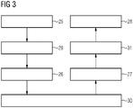
- FIG. 3 shows a flowchart for an exemplary embodiment variant of a maintenance method according to the invention for rail vehicles, for which a maintenance facility according to 1 and 2 is used and which one in 1 and 2 shown chassis 2 of a rail vehicle is carried out.
- a first carrying device 1 designed as a lifting platform and movably connected to a transport track 4 guided under the running gear 2 is first remotely guided under the running gear 2 to remove or dismantle the running gear 2 from the rail vehicle (first driving step 25) .
- a lifting platform 11 of the first carrying device 1 is raised hydraulically and remotely until wheel flange undersides of wheels of the running gear 2 are located above the upper rail edges of a maintenance track 3 on which the running gear 2 is supported before a lifting process (lifting step 29).
- the running gear 2 is decoupled from a car body of the rail vehicle arranged above it.
- the first carrying device 1 with the running gear 2 supported on it is remotely guided away on the transport track 4 from the maintenance track 3 to a maintenance station (second driving step 26). This completes the removal or dismantling of the chassis 2.
- Maintenance activities are carried out on the chassis 2 at the maintenance station (maintenance step 30).
- the running gear 2 is installed or assembled in the rail vehicle.
- the first carrying device 1 with the running gear 2 supported on it is first guided remotely from the maintenance area on the transport track 4 to the maintenance track 3 until the wheels of the running gear 2 are aligned with the maintenance track 3 (third driving step 27).
- the chassis 2 is coupled to the car body and the lifting platform 11 of the first carrying device 1 is lowered hydraulically and by remote control until the chassis 2 is supported on the maintenance track 3 (lowering step 31). Finally, the first carrying device 1 is guided away from the maintenance track 3 on the transport track 4 by remote control (fourth travel step 28).
Landscapes
- Engineering & Computer Science (AREA)
- Mechanical Engineering (AREA)
- Life Sciences & Earth Sciences (AREA)
- Geology (AREA)
- Structural Engineering (AREA)
- Transportation (AREA)
- Vehicle Cleaning, Maintenance, Repair, Refitting, And Outriggers (AREA)
Applications Claiming Priority (1)
| Application Number | Priority Date | Filing Date | Title |
|---|---|---|---|
| ATA50992/2020A AT524401A1 (de) | 2020-11-13 | 2020-11-13 | Wartungseinrichtung für Schienenfahrzeuge, Fahrwerk sowie Fahrwerkskomponente eines Schienenfahrzeugs und Wartungsverfahren |
Publications (3)
| Publication Number | Publication Date |
|---|---|
| EP4001046A1 true EP4001046A1 (fr) | 2022-05-25 |
| EP4001046C0 EP4001046C0 (fr) | 2024-06-05 |
| EP4001046B1 EP4001046B1 (fr) | 2024-06-05 |
Family
ID=78617181
Family Applications (1)
| Application Number | Title | Priority Date | Filing Date |
|---|---|---|---|
| EP21207770.5A Active EP4001046B1 (fr) | 2020-11-13 | 2021-11-11 | Dispositif de maintenance pour véhicules ferroviaires, train de roulement d'un véhicule ferroviaire et procédé de maintenance |
Country Status (3)
| Country | Link |
|---|---|
| EP (1) | EP4001046B1 (fr) |
| AT (1) | AT524401A1 (fr) |
| PL (1) | PL4001046T3 (fr) |
Citations (8)
| Publication number | Priority date | Publication date | Assignee | Title |
|---|---|---|---|---|
| US5370058A (en) * | 1993-11-15 | 1994-12-06 | Whiting Equipment Canada Inc. | Low rise drop yoke system |
| RU2099222C1 (ru) * | 1995-10-27 | 1997-12-20 | Научно-внедренческий центр "Путевые машины" Дальневосточной государственной академии путей сообщения | Устройство для замены тележек транспортного средства |
| EP1935746A1 (fr) * | 2006-12-22 | 2008-06-25 | NEUERO Technology GmbH | Voie ferrée de maintenance |
| RU2626425C1 (ru) * | 2016-08-09 | 2017-07-27 | Сергей Николаевич Еремеев | Способ замены колесных пар железнодорожного вагона (варианты) |
| DE202017005428U1 (de) * | 2017-10-20 | 2018-01-08 | Neuero Technology Gmbh | Wartungsgleisanlage |
| DE202019107158U1 (de) * | 2019-12-20 | 2020-05-14 | Beijing Magnetic-Flux Equipment Manufacturing Co., Ltd. | Vorrichtung zum Austausch eines Drehgestells für Schienenfahrzeuge |
| KR102114867B1 (ko) | 2018-12-05 | 2020-05-27 | 한국생산기술연구원 | 레일용 전복 안전 장치를 구비한 시설원예용 전기작업차 및 전복 안전 장치의 작동방법 |
| CN111469884A (zh) | 2020-04-21 | 2020-07-31 | 硕维科技(杭州)有限公司 | 一种地铁伺服架检修辅助设备 |
Family Cites Families (1)
| Publication number | Priority date | Publication date | Assignee | Title |
|---|---|---|---|---|
| JPS562589Y2 (fr) * | 1977-01-12 | 1981-01-21 |
-
2020
- 2020-11-13 AT ATA50992/2020A patent/AT524401A1/de unknown
-
2021
- 2021-11-11 EP EP21207770.5A patent/EP4001046B1/fr active Active
- 2021-11-11 PL PL21207770.5T patent/PL4001046T3/pl unknown
Patent Citations (8)
| Publication number | Priority date | Publication date | Assignee | Title |
|---|---|---|---|---|
| US5370058A (en) * | 1993-11-15 | 1994-12-06 | Whiting Equipment Canada Inc. | Low rise drop yoke system |
| RU2099222C1 (ru) * | 1995-10-27 | 1997-12-20 | Научно-внедренческий центр "Путевые машины" Дальневосточной государственной академии путей сообщения | Устройство для замены тележек транспортного средства |
| EP1935746A1 (fr) * | 2006-12-22 | 2008-06-25 | NEUERO Technology GmbH | Voie ferrée de maintenance |
| RU2626425C1 (ru) * | 2016-08-09 | 2017-07-27 | Сергей Николаевич Еремеев | Способ замены колесных пар железнодорожного вагона (варианты) |
| DE202017005428U1 (de) * | 2017-10-20 | 2018-01-08 | Neuero Technology Gmbh | Wartungsgleisanlage |
| KR102114867B1 (ko) | 2018-12-05 | 2020-05-27 | 한국생산기술연구원 | 레일용 전복 안전 장치를 구비한 시설원예용 전기작업차 및 전복 안전 장치의 작동방법 |
| DE202019107158U1 (de) * | 2019-12-20 | 2020-05-14 | Beijing Magnetic-Flux Equipment Manufacturing Co., Ltd. | Vorrichtung zum Austausch eines Drehgestells für Schienenfahrzeuge |
| CN111469884A (zh) | 2020-04-21 | 2020-07-31 | 硕维科技(杭州)有限公司 | 一种地铁伺服架检修辅助设备 |
Also Published As
| Publication number | Publication date |
|---|---|
| PL4001046T3 (pl) | 2024-10-21 |
| AT524401A1 (de) | 2022-05-15 |
| EP4001046C0 (fr) | 2024-06-05 |
| EP4001046B1 (fr) | 2024-06-05 |
Similar Documents
| Publication | Publication Date | Title |
|---|---|---|
| DE2146689A1 (de) | Verfahren und Anordnung zum Errichten von Turmkonstruktionen | |
| DE29819391U1 (de) | Vorrichtung zur Durchführung von Reparatur- und Serviceleistungen insbesondere an Rotorblättern von Windkraftanlagen | |
| DE2507983A1 (de) | Vorrichtung zum bewegen von schiffsbauteilen, z.b. zum versetzen vorgefertigter rumpfteile oder sonstiger teile eines schiffskoerpers | |
| EP1780167A2 (fr) | Grue automotrice avec contrepoids | |
| DE4022685C1 (en) | Rolling stock wheel-set change facility - uses sections, of track which drop to allow wheels to be removed | |
| EP0982217A1 (fr) | Dispositif de levage et d'abaissement combiné pour l'échange de sous-groupes aux véhicules ferroviaires sur voies élévées avec des fosses de l'inspection continues | |
| DE102006030432B3 (de) | Verfahren und Vorrichtung zum Wechseln von Unterflurbauteilen an Schienenfahrzeugen | |
| DE3702421C1 (en) | Method and means for renewing the fastening of equipment of the travel way for an electromagnetic high-speed railway | |
| EP0293359B1 (fr) | Wagon surbaissé à hauteur réglable pour trafic intermodal rail-route | |
| DE102008048356A1 (de) | Vorrichtung zum Verlegen einer vorgefertigten Auskleidung in U-Bahnstationen und Verkehrstunneln | |
| EP4001046B1 (fr) | Dispositif de maintenance pour véhicules ferroviaires, train de roulement d'un véhicule ferroviaire et procédé de maintenance | |
| EP1841919B1 (fr) | Procede pour nettoyer le ballast d'une voie ferree | |
| DE202006010225U1 (de) | Vorrichtung zum Wechseln von Unterflurbauteilen an Schienenfahrzeugen, insbesondere von Drehgestellen | |
| EP3670427B1 (fr) | Dispositif de levage encastré | |
| DE2945721C2 (de) | Verfahren zur Herstellung einer fahrbaren Gleisbehandlungsvorrichtung | |
| EP2988982B1 (fr) | Structure porteuse d'un véhicule ferroviaire | |
| DE19726359C2 (de) | Hydraulisch gelagertes Fahr- und Stützwerk für Containerbrücken in Modulbauweise | |
| DE102006062245B4 (de) | Wartungsgleisanlage | |
| EP4004289B1 (fr) | Procédé et appareil pour remplacer des ouvrages de pont dans des systèmes de voies ferrées | |
| DE102005020454A1 (de) | Verfahren und Vorrichtung zum Radsatzwechsel an Schienenfahrzeugen mittels einer verfahrbaren Einrichtung | |
| EP0690547B1 (fr) | Montage d'un stator dans une boíte | |
| EP3904270B1 (fr) | Dispositif de levage et procédé d'extraction d'un mât ou d'un poteau ancré dans une fondation | |
| DE4134041C1 (en) | Railway wheel-set hoist - has replacement bridges moved upwards in guide and automatically disengaged from main bridge | |
| DE10239518B3 (de) | Hallenanordnung mit mehreren Hallenfeldern | |
| DE1658602B1 (de) | Vorrichtung zum Montieren der jeweils einen vollstaendigen Brueckenabschnitt umfassenden Fertigbauteile einer Spannbetonbruecke im abschnittsweisen Freivorbau |
Legal Events
| Date | Code | Title | Description |
|---|---|---|---|
| PUAI | Public reference made under article 153(3) epc to a published international application that has entered the european phase |
Free format text: ORIGINAL CODE: 0009012 |
|
| STAA | Information on the status of an ep patent application or granted ep patent |
Free format text: STATUS: THE APPLICATION HAS BEEN PUBLISHED |
|
| AK | Designated contracting states |
Kind code of ref document: A1 Designated state(s): AL AT BE BG CH CY CZ DE DK EE ES FI FR GB GR HR HU IE IS IT LI LT LU LV MC MK MT NL NO PL PT RO RS SE SI SK SM TR |
|
| STAA | Information on the status of an ep patent application or granted ep patent |
Free format text: STATUS: REQUEST FOR EXAMINATION WAS MADE |
|
| 17P | Request for examination filed |
Effective date: 20221118 |
|
| RBV | Designated contracting states (corrected) |
Designated state(s): AL AT BE BG CH CY CZ DE DK EE ES FI FR GB GR HR HU IE IS IT LI LT LU LV MC MK MT NL NO PL PT RO RS SE SI SK SM TR |
|
| GRAP | Despatch of communication of intention to grant a patent |
Free format text: ORIGINAL CODE: EPIDOSNIGR1 |
|
| STAA | Information on the status of an ep patent application or granted ep patent |
Free format text: STATUS: GRANT OF PATENT IS INTENDED |
|
| RIC1 | Information provided on ipc code assigned before grant |
Ipc: B66F 7/28 20060101ALI20231211BHEP Ipc: B66F 7/18 20060101ALI20231211BHEP Ipc: B61K 5/04 20060101ALI20231211BHEP Ipc: B61K 5/00 20060101ALI20231211BHEP Ipc: B61B 15/00 20060101AFI20231211BHEP |
|
| INTG | Intention to grant announced |
Effective date: 20240111 |
|
| GRAS | Grant fee paid |
Free format text: ORIGINAL CODE: EPIDOSNIGR3 |
|
| GRAA | (expected) grant |
Free format text: ORIGINAL CODE: 0009210 |
|
| STAA | Information on the status of an ep patent application or granted ep patent |
Free format text: STATUS: THE PATENT HAS BEEN GRANTED |
|
| AK | Designated contracting states |
Kind code of ref document: B1 Designated state(s): AL AT BE BG CH CY CZ DE DK EE ES FI FR GB GR HR HU IE IS IT LI LT LU LV MC MK MT NL NO PL PT RO RS SE SI SK SM TR |
|
| REG | Reference to a national code |
Ref country code: CH Ref legal event code: EP |
|
| REG | Reference to a national code |
Ref country code: DE Ref legal event code: R096 Ref document number: 502021003917 Country of ref document: DE |
|
| REG | Reference to a national code |
Ref country code: IE Ref legal event code: FG4D Free format text: LANGUAGE OF EP DOCUMENT: GERMAN |
|
| U01 | Request for unitary effect filed |
Effective date: 20240624 |
|
| U07 | Unitary effect registered |
Designated state(s): AT BE BG DE DK EE FI FR IT LT LU LV MT NL PT SE SI Effective date: 20240704 |
|
| PG25 | Lapsed in a contracting state [announced via postgrant information from national office to epo] |
Ref country code: HR Free format text: LAPSE BECAUSE OF FAILURE TO SUBMIT A TRANSLATION OF THE DESCRIPTION OR TO PAY THE FEE WITHIN THE PRESCRIBED TIME-LIMIT Effective date: 20240605 |
|
| PG25 | Lapsed in a contracting state [announced via postgrant information from national office to epo] |
Ref country code: GR Free format text: LAPSE BECAUSE OF FAILURE TO SUBMIT A TRANSLATION OF THE DESCRIPTION OR TO PAY THE FEE WITHIN THE PRESCRIBED TIME-LIMIT Effective date: 20240906 |
|
| PG25 | Lapsed in a contracting state [announced via postgrant information from national office to epo] |
Ref country code: ES Free format text: LAPSE BECAUSE OF FAILURE TO SUBMIT A TRANSLATION OF THE DESCRIPTION OR TO PAY THE FEE WITHIN THE PRESCRIBED TIME-LIMIT Effective date: 20240605 |
|
| PG25 | Lapsed in a contracting state [announced via postgrant information from national office to epo] |
Ref country code: NO Free format text: LAPSE BECAUSE OF FAILURE TO SUBMIT A TRANSLATION OF THE DESCRIPTION OR TO PAY THE FEE WITHIN THE PRESCRIBED TIME-LIMIT Effective date: 20240905 Ref country code: HR Free format text: LAPSE BECAUSE OF FAILURE TO SUBMIT A TRANSLATION OF THE DESCRIPTION OR TO PAY THE FEE WITHIN THE PRESCRIBED TIME-LIMIT Effective date: 20240605 Ref country code: GR Free format text: LAPSE BECAUSE OF FAILURE TO SUBMIT A TRANSLATION OF THE DESCRIPTION OR TO PAY THE FEE WITHIN THE PRESCRIBED TIME-LIMIT Effective date: 20240906 Ref country code: ES Free format text: LAPSE BECAUSE OF FAILURE TO SUBMIT A TRANSLATION OF THE DESCRIPTION OR TO PAY THE FEE WITHIN THE PRESCRIBED TIME-LIMIT Effective date: 20240605 Ref country code: RS Free format text: LAPSE BECAUSE OF FAILURE TO SUBMIT A TRANSLATION OF THE DESCRIPTION OR TO PAY THE FEE WITHIN THE PRESCRIBED TIME-LIMIT Effective date: 20240905 |
|
| U20 | Renewal fee for the european patent with unitary effect paid |
Year of fee payment: 4 Effective date: 20241118 |
|
| PG25 | Lapsed in a contracting state [announced via postgrant information from national office to epo] |
Ref country code: IS Free format text: LAPSE BECAUSE OF FAILURE TO SUBMIT A TRANSLATION OF THE DESCRIPTION OR TO PAY THE FEE WITHIN THE PRESCRIBED TIME-LIMIT Effective date: 20241005 |
|
| PG25 | Lapsed in a contracting state [announced via postgrant information from national office to epo] |
Ref country code: CZ Free format text: LAPSE BECAUSE OF FAILURE TO SUBMIT A TRANSLATION OF THE DESCRIPTION OR TO PAY THE FEE WITHIN THE PRESCRIBED TIME-LIMIT Effective date: 20240605 |
|
| PG25 | Lapsed in a contracting state [announced via postgrant information from national office to epo] |
Ref country code: RO Free format text: LAPSE BECAUSE OF FAILURE TO SUBMIT A TRANSLATION OF THE DESCRIPTION OR TO PAY THE FEE WITHIN THE PRESCRIBED TIME-LIMIT Effective date: 20240605 Ref country code: SK Free format text: LAPSE BECAUSE OF FAILURE TO SUBMIT A TRANSLATION OF THE DESCRIPTION OR TO PAY THE FEE WITHIN THE PRESCRIBED TIME-LIMIT Effective date: 20240605 |
|
| PG25 | Lapsed in a contracting state [announced via postgrant information from national office to epo] |
Ref country code: SM Free format text: LAPSE BECAUSE OF FAILURE TO SUBMIT A TRANSLATION OF THE DESCRIPTION OR TO PAY THE FEE WITHIN THE PRESCRIBED TIME-LIMIT Effective date: 20240605 |
|
| PG25 | Lapsed in a contracting state [announced via postgrant information from national office to epo] |
Ref country code: SM Free format text: LAPSE BECAUSE OF FAILURE TO SUBMIT A TRANSLATION OF THE DESCRIPTION OR TO PAY THE FEE WITHIN THE PRESCRIBED TIME-LIMIT Effective date: 20240605 Ref country code: SK Free format text: LAPSE BECAUSE OF FAILURE TO SUBMIT A TRANSLATION OF THE DESCRIPTION OR TO PAY THE FEE WITHIN THE PRESCRIBED TIME-LIMIT Effective date: 20240605 Ref country code: RO Free format text: LAPSE BECAUSE OF FAILURE TO SUBMIT A TRANSLATION OF THE DESCRIPTION OR TO PAY THE FEE WITHIN THE PRESCRIBED TIME-LIMIT Effective date: 20240605 Ref country code: IS Free format text: LAPSE BECAUSE OF FAILURE TO SUBMIT A TRANSLATION OF THE DESCRIPTION OR TO PAY THE FEE WITHIN THE PRESCRIBED TIME-LIMIT Effective date: 20241005 Ref country code: CZ Free format text: LAPSE BECAUSE OF FAILURE TO SUBMIT A TRANSLATION OF THE DESCRIPTION OR TO PAY THE FEE WITHIN THE PRESCRIBED TIME-LIMIT Effective date: 20240605 |
|
| PLBE | No opposition filed within time limit |
Free format text: ORIGINAL CODE: 0009261 |
|
| STAA | Information on the status of an ep patent application or granted ep patent |
Free format text: STATUS: NO OPPOSITION FILED WITHIN TIME LIMIT |
|
| 26N | No opposition filed |
Effective date: 20250306 |
|
| REG | Reference to a national code |
Ref country code: CH Ref legal event code: PL |
|
| PG25 | Lapsed in a contracting state [announced via postgrant information from national office to epo] |
Ref country code: MC Free format text: LAPSE BECAUSE OF FAILURE TO SUBMIT A TRANSLATION OF THE DESCRIPTION OR TO PAY THE FEE WITHIN THE PRESCRIBED TIME-LIMIT Effective date: 20240605 |
|
| REG | Reference to a national code |
Ref country code: CH Ref legal event code: PL |
|
| PG25 | Lapsed in a contracting state [announced via postgrant information from national office to epo] |
Ref country code: CH Free format text: LAPSE BECAUSE OF NON-PAYMENT OF DUE FEES Effective date: 20241130 |
|
| PG25 | Lapsed in a contracting state [announced via postgrant information from national office to epo] |
Ref country code: IE Free format text: LAPSE BECAUSE OF NON-PAYMENT OF DUE FEES Effective date: 20241111 |
|
| U20 | Renewal fee for the european patent with unitary effect paid |
Year of fee payment: 5 Effective date: 20251120 |
|
| PGFP | Annual fee paid to national office [announced via postgrant information from national office to epo] |
Ref country code: PL Payment date: 20251030 Year of fee payment: 5 |
|
| PG25 | Lapsed in a contracting state [announced via postgrant information from national office to epo] |
Ref country code: HU Free format text: LAPSE BECAUSE OF FAILURE TO SUBMIT A TRANSLATION OF THE DESCRIPTION OR TO PAY THE FEE WITHIN THE PRESCRIBED TIME-LIMIT; INVALID AB INITIO Effective date: 20211111 |
|
| PG25 | Lapsed in a contracting state [announced via postgrant information from national office to epo] |
Ref country code: CY Free format text: LAPSE BECAUSE OF FAILURE TO SUBMIT A TRANSLATION OF THE DESCRIPTION OR TO PAY THE FEE WITHIN THE PRESCRIBED TIME-LIMIT; INVALID AB INITIO Effective date: 20211111 |