EP4001102B1 - Rotoranordnungen für einen drehflügler - Google Patents
Rotoranordnungen für einen drehflügler Download PDFInfo
- Publication number
- EP4001102B1 EP4001102B1 EP21186242.0A EP21186242A EP4001102B1 EP 4001102 B1 EP4001102 B1 EP 4001102B1 EP 21186242 A EP21186242 A EP 21186242A EP 4001102 B1 EP4001102 B1 EP 4001102B1
- Authority
- EP
- European Patent Office
- Prior art keywords
- rotor
- blade
- connector
- bearing
- hub
- Prior art date
- Legal status (The legal status is an assumption and is not a legal conclusion. Google has not performed a legal analysis and makes no representation as to the accuracy of the status listed.)
- Active
Links
Images




Classifications
-
- B—PERFORMING OPERATIONS; TRANSPORTING
- B64—AIRCRAFT; AVIATION; COSMONAUTICS
- B64C—AEROPLANES; HELICOPTERS
- B64C27/00—Rotorcraft; Rotors peculiar thereto
- B64C27/32—Rotors
- B64C27/46—Blades
- B64C27/473—Constructional features
-
- B—PERFORMING OPERATIONS; TRANSPORTING
- B64—AIRCRAFT; AVIATION; COSMONAUTICS
- B64C—AEROPLANES; HELICOPTERS
- B64C27/00—Rotorcraft; Rotors peculiar thereto
- B64C27/32—Rotors
- B64C27/37—Rotors having articulated joints
- B64C27/39—Rotors having articulated joints with individually articulated blades, i.e. with flapping or drag hinges
-
- B—PERFORMING OPERATIONS; TRANSPORTING
- B64—AIRCRAFT; AVIATION; COSMONAUTICS
- B64C—AEROPLANES; HELICOPTERS
- B64C27/00—Rotorcraft; Rotors peculiar thereto
- B64C27/54—Mechanisms for controlling blade adjustment or movement relative to rotor head, e.g. lag-lead movement
- B64C27/78—Mechanisms for controlling blade adjustment or movement relative to rotor head, e.g. lag-lead movement in association with pitch adjustment of blades of anti-torque rotor
-
- B—PERFORMING OPERATIONS; TRANSPORTING
- B64—AIRCRAFT; AVIATION; COSMONAUTICS
- B64C—AEROPLANES; HELICOPTERS
- B64C11/00—Propellers, e.g. of ducted type; Features common to propellers and rotors for rotorcraft
- B64C11/02—Hub construction
- B64C11/04—Blade mountings
- B64C11/06—Blade mountings for variable-pitch blades
-
- B—PERFORMING OPERATIONS; TRANSPORTING
- B64—AIRCRAFT; AVIATION; COSMONAUTICS
- B64C—AEROPLANES; HELICOPTERS
- B64C27/00—Rotorcraft; Rotors peculiar thereto
- B64C27/32—Rotors
- B64C27/33—Rotors having flexing arms
-
- B—PERFORMING OPERATIONS; TRANSPORTING
- B64—AIRCRAFT; AVIATION; COSMONAUTICS
- B64C—AEROPLANES; HELICOPTERS
- B64C27/00—Rotorcraft; Rotors peculiar thereto
- B64C27/32—Rotors
- B64C27/35—Rotors having elastomeric joints
-
- B—PERFORMING OPERATIONS; TRANSPORTING
- B64—AIRCRAFT; AVIATION; COSMONAUTICS
- B64C—AEROPLANES; HELICOPTERS
- B64C27/00—Rotorcraft; Rotors peculiar thereto
- B64C27/32—Rotors
- B64C27/46—Blades
- B64C27/473—Constructional features
- B64C27/48—Root attachment to rotor head
-
- B—PERFORMING OPERATIONS; TRANSPORTING
- B64—AIRCRAFT; AVIATION; COSMONAUTICS
- B64C—AEROPLANES; HELICOPTERS
- B64C27/00—Rotorcraft; Rotors peculiar thereto
- B64C27/54—Mechanisms for controlling blade adjustment or movement relative to rotor head, e.g. lag-lead movement
- B64C27/58—Transmitting means, e.g. interrelated with initiating means or means acting on blades
- B64C27/59—Transmitting means, e.g. interrelated with initiating means or means acting on blades mechanical
- B64C27/605—Transmitting means, e.g. interrelated with initiating means or means acting on blades mechanical including swash plate, spider or cam mechanisms
-
- B—PERFORMING OPERATIONS; TRANSPORTING
- B64—AIRCRAFT; AVIATION; COSMONAUTICS
- B64C—AEROPLANES; HELICOPTERS
- B64C27/00—Rotorcraft; Rotors peculiar thereto
- B64C27/82—Rotorcraft; Rotors peculiar thereto characterised by the provision of an auxiliary rotor or fluid-jet device for counter-balancing lifting rotor torque or changing direction of rotorcraft
Definitions
- the present disclosure relates to rotor assemblies for rotorcraft.
- Helicopters typically comprise a main rotor and a tail rotor. Both rotors are complex assemblies, having rotor blades, each typically configured to be controllably pitched (i.e., rotated about an axis, substantially perpendicular to the rotor's rotation axis) and to passively flap (deflect back and forth along a plane, containing the rotor's rotation ais-i.e., out of the plane, within which the rotor blades rotate).
- US 3 520 637 A discloses a rotor assembly for a rotorcraft comprising a rotor hub with rotor-blade supports and rotor-blade assemblies, each coupled to a respective one of the rotor-blade supports and comprising a flap axle, a hub connector, a rotor blade and a torsion strap.
- rotors comprise thrust and pitch bearing joints, which require periodic lubrication.
- the rotor assembly comprises a rotor hub and rotor-blade assemblies.
- the rotor hub comprises rotor-blade supports.
- Each of the rotor-blade assemblies is coupled to a respective one of the rotor-blade supports.
- the rotor hub has a rotation axis about which the rotor hub has a rotational symmetry of order N.
- the rotor-blade supports are N in number.
- Each of the rotor-blade assemblies comprises a flap axle, a hub connector, a rotor blade, and a torsion strap.
- the flap axle extends through a respective one of the rotor-blade supports and has a central flap-axle axis.
- the hub connector is coupled to a respective one of the rotor-blade supports via the flap axle, is pivotable relative to a respective one of the rotor-blade supports about the central flap-axle axis, and defines a central hub-connector axis that is perpendicular to the central flap-axle axis.
- the rotor blade is coupled to the hub connector, is pivotable relative to the hub connector about the central hub-connector axis, and, together with the hub connector, is pivotable relative to a respective one of the rotor-blade supports about the central flap-axle axis.
- the torsion strap has a first end, coupled to the rotor blade, and a second end, through which the flap axle passes.
- rotor-blade assemblies including those with greater than two rotor blades, may include a single rotor hub, with rotor blade assemblies extending from the rotor hub in the same plane. Such a configuration reduces complexity and the envelope, or packaging volume, of the rotor assembly, compared to rotor assemblies in which each opposing pair of rotor blades extends in a distinct plane, as often is the case with tail rotor designs.
- Fig. 1 solid lines, if any, connecting various elements and/or components may represent mechanical, electrical, fluid, optical, electromagnetic and other couplings and/or combinations thereof.
- "coupled” means associated directly as well as indirectly.
- a member A may be directly associated with a member B, or may be indirectly associated therewith, e.g., via another member C. It will be understood that not all relationships among the various disclosed elements are necessarily represented. Accordingly, couplings other than those depicted in the block diagrams may also exist.
- Dashed lines, if any, connecting blocks designating the various elements and/or components represent couplings similar in function and purpose to those represented by solid lines; however, couplings represented by the dashed lines may either be selectively provided or may relate to alternative examples of the subject matter, disclosed herein.
- elements and/or components, if any, represented with dashed lines indicate alternative examples of the subject matter, disclosed herein.
- One or more elements shown in solid and/or dashed lines may be omitted from a particular example without departing from the scope of the subject matter, disclosed herein.
- Environmental elements, if any, are represented with dotted lines. Virtual (imaginary) elements may also be shown for clarity.
- the blocks may represent operations and/or portions thereof and lines connecting the various blocks do not imply any particular order or dependency of the operations or portions thereof. Blocks represented by dashed lines indicate alternative operations and/or portions thereof. Dashed lines, if any, connecting the various blocks represent alternative dependencies of the operations or portions thereof. It will be understood that not all dependencies among the various disclosed operations are necessarily represented.
- Fig. 7 and the accompanying disclosure describing the operations of the method(s) set forth herein should not be interpreted as necessarily determining a sequence in which the operations are to be performed. Rather, although one illustrative order is indicated, it is to be understood that the sequence of the operations may be modified when appropriate. Accordingly, certain operations may be performed in a different order or simultaneously. Additionally, those skilled in the art will appreciate that not all operations described need be performed.
- first, second, etc. are used herein merely as labels, and are not intended to impose ordinal, positional, or hierarchical requirements on the items to which these terms refer. Moreover, reference to, e.g., a “second” item does not require or preclude the existence of, e.g., a "first” or lower-numbered item, and/or, e.g., a "third" or higher-numbered item.
- a system, apparatus, structure, article, element, component, or hardware “configured to” perform a specified function is indeed capable of performing the specified function without any alteration, rather than merely having potential to perform the specified function after further modification.
- the system, apparatus, structure, article, element, component, or hardware “configured to” perform a specified function is specifically selected, created, implemented, utilized, programmed, and/or designed for the purpose of performing the specified function.
- "configured to” denotes existing characteristics of a system, apparatus, structure, article, element, component, or hardware which enable the system, apparatus, structure, article, element, component, or hardware to perform the specified function without further modification.
- a system, apparatus, structure, article, element, component, or hardware described as being “configured to” perform a particular function may additionally or alternatively be described as being “adapted to” and/or as being “operative to” perform that function.
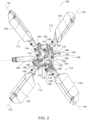
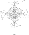
- rotor assembly 100 for rotorcraft 102 comprises rotor hub 104 and rotor-blade assemblies 112.
- Rotor hub 104 comprises rotor-blade supports 108.
- Each of rotor-blade assemblies 112 is coupled to a respective one of rotor-blade supports 108.
- Rotor hub 104 has rotation axis 106, about which rotor hub 104 has a rotational symmetry of order N.
- Rotor-blade supports 108 are N in number.
- Each of rotor-blade assemblies 112 comprises flap axle 114, hub connector 116, rotor blade 120, and torsion strap 122.
- Flap axle 114 extends through a respective one of rotor-blade supports 108 and has central flap-axle axis 110.
- Hub connector 116 is coupled to a respective one of rotor-blade supports 108 via flap axle 114, is pivotable relative to a respective one of rotor-blade supports 108 about central flap-axle axis 110, and defines central hub-connector axis 118 that is perpendicular to central flap-axle axis 110.
- Rotor blade 120 is coupled to hub connector 116, is pivotable relative to hub connector 116 about central hub-connector axis 118, and, together with hub connector 116, is pivotable relative to a respective one of rotor-blade supports 108 about central flap-axle axis 110.
- Torsion strap 122 has first end 124, coupled to rotor blade 120, and second end 126, through which flap axle 114 passes.
- rotor-blade assemblies 112 By having each rotor blade 120 with its own torsion strap, as opposed to a single torsion strap extending between two opposing rotor blades, rotor-blade assemblies 112, including those with greater than two rotor blades, may include a single rotor hub, with rotor-blade assemblies 112 extending from rotor hub 104 in the same plane. Such a configuration reduces complexity and the envelope, or packaging volume, of rotor assembly 100, compared to rotor assemblies in which each opposing pair of rotor blades extends in a distinct plane (e.g., with stacked hubs), as often is the case with tail rotor designs.
- central flap-axle axis 110 also is referred to as a flap axis
- central hub-connector axis 118 also is referred to as a rotor-blade pitch axis.
- pairs of rotor blades may be directly across rotor hub 104 from each other, thereby countering, or reacting against, the corresponding centrifugal forces of the rotor blades.
- example 3 of the subject matter, disclosed herein. According to example 3, which encompasses example 1, above, N is an odd number.
- rotor assembly 100 may be constructed to be stiff without introducing stability issues that may result from an even number of rotor blades.
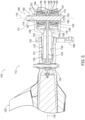
- hub connector 116 comprises connector shaft 127, first clamp arm 125 that extends from connector shaft 127 toward rotor hub 104, and second clamp arm 128 that extends from connector shaft 127 toward rotor hub 104.
- Rotor blade 120 is pivotable relative to connector shaft 127 about central hub-connector axis 118.
- Flap axle 114 extends through first clamp arm 125 and second clamp arm 128 of hub connector 116.
- Connector shaft 127 facilitates pitch adjustment of rotor blade 120.
- First clamp arm 125 and second clamp arm 128 facilitate coupling of a respective rotor blade assembly to a respective rotor-blade support of rotor hub 104 via the corresponding flap axle.
- the relationship of first clamp arm 125 and second clamp arm 128 with flap axle 114 further facilitates flap movement of the corresponding one of rotor-blade assemblies 112.
- rotor blade 120 comprises blade shaft 129.
- Blade shaft 129 comprises blade-shaft internal cavity 131.
- Connector shaft 127 of hub connector 116 is positioned at least partially within blade-shaft internal cavity 131.
- Blade shaft 129 of rotor blade 120 is pivotable relative to connector shaft 127 of hub connector 116 about central hub-connector axis 118.
- blade shaft 129 of rotor blade 120 is pivotally supported relative to connector shaft 127 of hub connector 116 via bearing element 130, located inside blade-shaft internal cavity 131.
- Bearing element 130 constrains the pitch movement of the corresponding rotor blade.
- bearing element 130 comprises two bearing elements, spaced apart from each other along central hub-connector axis 118.
- the bearing elements counter, or react, torques applied to connector shaft 127 by blade shaft 129, such as a result of flap motion and chord-wise motion of the corresponding rotor blade or undesirable pivotal forces applied by rotor blade 120, such as due to wind or other external forces.
- connector shaft 127 of hub connector 116 defines connector-shaft internal cavity 134. At least a portion of torsion strap 122 is located inside connector-shaft internal cavity 134.
- torsion strap 122 prefferably extends along central hub-connector axis 118 and thus along the vector of the corresponding centrifugal force resulting from the rotation of the corresponding rotor blade about rotation axis 106.
- each of rotor-blade supports 108 comprises pair of bearing assemblies 140. Flap axle 114 of each of rotor-blade assemblies 112 is received within and supported by pair of bearing assemblies 140 of a respective one of rotor-blade supports 108. Pair of bearing assemblies 140 is configured such that rotation of each of rotor-blade assemblies 112 relative to a respective one of rotor-blade supports 108 about central flap-axle axis 110 is angularly limited.
- the bearing assemblies limit the available flap motion of the rotor blades relative to rotor hub 104.
- off-the-shelf bearing assemblies may be selected or the bearing assemblies may be customized with a desired limitation of movement between the inner and outer races of the bearing assemblies.
- each one of pair of bearing assemblies 140 is an elastomeric bearing assembly.
- Elastomeric bearing assemblies have desirable resilient characteristics for limiting flap motion of rotor blades without harsh stops at the full extent of their permitted motion. Moreover, elastomeric bearing assemblies have desirable longevity and maintenance characteristics when used in rotor applications, such as helicopter tail rotor applications. For example, elastomeric bearing assemblies do not require lubrication.
- each of pair of bearing assemblies 140 comprises inner race 142, outer race 144, and elastomeric layer 146 between inner race 142 and outer race 144.
- Bearing assemblies 140 therefore may be customized with selection of material of elastomeric layer 146 to result in desired flap motion characteristics.
- inner race 142 and outer race 144 are constructed of steel or other hard metal, and elastomeric layer 146 is constructed of rubber or other resilient elastomeric material.
- each pair of bearing assemblies 140 further comprises additional elastomeric layer 147 and metallic shim 149 that is located between elastomeric layer 146 and additional elastomeric layer 147.
- Bearing assemblies 140 therefore may be customized with selection of number and material of elastomeric layers and metallic shims to result in desired flap motion characteristics.
- additional elastomeric layer 147 is constructed of rubber or other resilient elastomeric material
- metallic shim 149 is constructed of steel or other metal.
- elastomeric layer 146 and additional elastomeric layer 147 are coaxially arranged conical frustums, comprising respective single frustoconical central openings, having different volumes.
- inner race 142 of each one of bearing assemblies 140 is elastomerically supported relative to outer race 144.
- pair of bearing assemblies 140 are described as conical bearing assemblies.
- each of pair of bearing assemblies 140 comprises inner race 142, outer race 144, elastomeric layers 151 between inner race 142 and outer race 144, and metallic shims 148, interspersed among elastomeric layers 151.
- Bearing assemblies 140 therefore may be customized with selection of number and material of elastomeric layers 151 and metallic shims 148 to result in desired flap motion characteristics.
- elastomeric layers are constructed of rubber or other resilient elastomeric material
- metallic shims are constructed of steel or other metal.
- example 15 of the subject matter, disclosed herein.
- metallic shims 148 separate elastomeric layers 151 from each other.
- bearing assemblies 140 therefore may be customized with selection of number and material of elastomeric layers 151 and metallic shims 148 to result in desired flap motion characteristics.
- elastomeric layers 151 are coaxially arranged conical frustums, comprising respective single frustoconical central openings, having different volumes.
- inner race 142 of each one of the bearing assemblies 140 is elastomerically supported relative to outer race 144.
- pair of bearing assemblies 140 are described as conical bearing assemblies.
- flap axle 114 of each of rotor-blade assemblies 112 extends through, and is fixed relative to, inner race 142 of each of pair of bearing assemblies 140 of a respective one of rotor-blade supports 108.
- Outer race 144 of each of pair of bearing assemblies 140 is fixed to a respective one of rotor-blade supports 108.
- Flap axle 114 is fixed relative to hub connector 116.
- Inner race 142 thereby pivots with flap axle 114 and the rest of the corresponding rotor-blade assembly about central flap-axle axis 110 when the rotor-blade assembly flaps. That is, the entirety of the corresponding rotor-blade assembly flaps as a unitary structure, and other than the relative pitch movement of rotor blade 120 relative to hub connector 116, the bearing assemblies operatively constrain all other movement of the rotor-blade assembly relative to rotor hub 104.
- first clamp arm 125 comprises first axle hole 152
- second clamp arm 128 comprises second axle hole 153.
- Each of rotor-blade assemblies 112 further comprises bushing 150.
- Bushing 150 is positioned in first axle hole 152 or in second axle hole 153.
- Flap axle 114 extends through bushing 150, first axle hole 152, and second axle hole 153.
- Bushing 150 abuts inner race 142 of one of pair of bearing assemblies 140 of a respective one of rotor-blade supports 108.
- clamp arms, flap axle 114, and bushing 150 are able to be clamped together with the inner races of the bearing assemblies, thereby fixing rotor blade 120 to the inner races, such that the bearing assemblies serve to limit the flap motion of rotor blade 120.
- first axle hole 152 is larger than second axle hole 153.
- Bushing 150 is positioned in first axle hole 152.
- Flap axle 114 fits in a close slip fit arrangement with second axle hole 153 and within the bore of bushing 150, while bushing 150 fits in a close slip fit arrangement with first axle hole 152, making for ease of assembly and ultimate fixing of central flap-axle axis 110 when clamped together.
- each of rotor-blade assemblies 112 further comprises first bearing-preload shim 154 and second bearing-preload shim 155, respectively positioned on opposing sides of second end 126 of torsion strap 122.
- Flap axle 114 extends through first bearing-preload shim 154 and through second bearing-preload shim 155.
- First bearing-preload shim 154 and second bearing-preload shim 155 are in contact with and are fixed relative to inner race 142 of a respective one of pair of bearing assemblies 140 of a respective one of rotor-blade supports 108.
- the bearing-preload shims in effect sandwich torsion strap 122, such that torsion strap 122 with the bearing-preload shims are clamped together with the clamp arms, flap axle 114, and bushing 150, such that second end 126 of torsion strap 122 is fixed to flap axle 114. Accordingly, the entirety of a rotor-blade assembly is fixed relative to and pivots with the inner races of the bearing assemblies.
- multiple bearing-preload shims and bearing-preload shims of different thicknesses may be selected and installed on opposing sides of second end 126 of torsion strap 122 to provide any desired degree of preload of the bearing assemblies.
- flap axle 114 comprises fastener pair 156.
- Fastener pair 156 is configured to draw together under pressure first clamp arm 125, second clamp arm 128, bushing 150, inner race 142 of each one of pair of bearing assemblies 140 of a respective one of rotor-blade supports 108, first bearing-preload shim 154, second bearing-preload shim 155, and second end 126 of torsion strap 122 to fix hub connector 116 relative to inner race 142 of each one of pair of bearing assemblies 140 of a respective one of rotor-blade supports 108.
- Fastener pair 156 operatively fixes the entirety of rotor blade 120 to the inner races of the bearing assemblies, so that the bearing assemblies function to limit the flap motion of rotor blade 120.
- fastener pair 156 comprises a bolt and a nut or a lockbolt (e.g., a pin and a collar).
- inner race 142 of each one of pair of bearing assemblies 140 of each one of rotor-blade supports 108 is a conical frustum, comprising a cylindrical central opening, leading end 168, and trailing end 170 that is larger than leading end 168.
- Leading end 168 is in contact with a respective one of first bearing-preload shim 154 or second bearing-preload shim 155 of a respective one of rotor-blade assemblies 112.
- the inner races of the bearing assemblies when compressed by fastener pair 156 toward torsion strap 122 and against the bearing-preload shims, cause one or more elastomeric layers to be compressed between the inner races and the outer races of bearing assemblies 140.
- each of pair of bearing assemblies 140 is a tapered bearing assembly.
- the bearing assemblies are able to be preloaded when operatively installed.
- pair of bearing assemblies 140 are described as conical bearing assemblies.
- rotor hub 104 comprises central body region 136, through which rotation axis 106 passes.
- Rotor-blade supports 108 extend from central body region 136 away from rotation axis 106.
- each of rotor-blade supports 108 By extending from central body region 136, each of rotor-blade supports 108 provides structure for operative coupling of a corresponding one of rotor-blade assemblies 112.
- each of rotor-blade supports 108 comprises internal channel 138.
- Flap axle 114 of each one of rotor-blade assemblies 112 is perpendicular to internal channel 138 of a respective one of rotor-blade supports 108.
- Second end 126 of torsion strap 122 of each one of rotor-blade assemblies 112 extends into internal channel 138 of a respective one of rotor-blade supports 108 and is coupled to flap axle 114.
- Presence of internal channel 138 enables second end 126 or torsion strap 122 to be coupled to flap axle 114 along central hub-connector axis 118 and thus along the vector of the corresponding centrifugal force resulting from the rotation of the corresponding rotor blade about rotation axis 106.
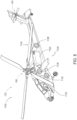
- rotor assembly 100 further comprises pitch control mechanism 158, configured to selectively pivot rotor blade 120 about central hub-connector axis 118.
- Pitch control of rotor blades enables selective adjustment of the thrust, produced by rotor assembly 100.
- pitch control mechanism 158 comprises body 160 and pitch-control links 164.
- Body 160 is translatable along rotation axis 106.
- Body 160 comprises pitch control arms 162.
- Rotor blade 120 comprises pitch lever 166.
- Pitch-control links 164 interconnect respective ones of pitch control arms 162 of body 160 and pitch lever 166 of rotor blade 120.
- the pitch of each of the rotor blades of rotor assembly 100 are controlled collectively when body 160 translates along rotation axis 106.
- aircraft 1102 is rotorcraft 102.
- illustrative method 1100 may include specification and design (block 1104) of aircraft 1102 and material procurement (block 1106).
- component and subassembly manufacturing (block 1108) and system integration (block 1110) of aircraft 1102 may take place.
- aircraft 1102 may go through certification and delivery (block 1112) to be placed in service (block 1114).
- aircraft 1102 may be scheduled for routine maintenance and service (block 1116). Routine maintenance and service may include modification, reconfiguration, refurbishment, etc. of one or more systems of aircraft 1102.
- a system integrator may include, without limitation, any number of aircraft manufacturers and major-system subcontractors; a third party may include, without limitation, any number of vendors, subcontractors, and suppliers; and an operator may be an airline, leasing company, military entity, service organization, and so on.
- aircraft 1102 produced by illustrative method 1100 may include airframe 1118 with a plurality of high-level systems 1120 and interior 1122.
- high-level systems 1120 include one or more of propulsion system 1124, electrical system 1126, hydraulic system 1128, and environmental system 1130. Any number of other systems may be included.
- propulsion system 1124 one or more of propulsion system 1124, electrical system 1126, hydraulic system 1128, and environmental system 1130. Any number of other systems may be included.
- propulsion system 1124 include one or more of propulsion system 1124, electrical system 1126, hydraulic system 1128, and environmental system 1130. Any number of other systems may be included.
- propulsion system 1124 include one or more of propulsion system 1124, electrical system 1126, hydraulic system 1128, and environmental system 1130. Any number of other systems may be included.
- electrical system 1126 electrical system 1126
- hydraulic system 1128 hydraulic system 1128
- environmental system 1130 any number of other systems may be included.
- Any number of other systems may be included.
- Apparatus(es) and method(s) shown or described herein may be employed during any one or more of the stages of the manufacturing and service method 1100.
- components or subassemblies corresponding to component and subassembly manufacturing (block 1108) may be fabricated or manufactured in a manner similar to components or subassemblies produced while aircraft 1102 is in service (block 1114).
- one or more examples of the apparatus(es), method(s), or combination thereof may be utilized during production stages 1108 and 1110, for example, by substantially expediting assembly of or reducing the cost of aircraft 1102.
- one or more examples of the apparatus or method realizations, or a combination thereof may be utilized, for example and without limitation, while aircraft 1102 is in service (block 1114) and/or during maintenance and service (block 1116).
Landscapes
- Engineering & Computer Science (AREA)
- Aviation & Aerospace Engineering (AREA)
- Mechanical Engineering (AREA)
- Wind Motors (AREA)
- Turbine Rotor Nozzle Sealing (AREA)
Claims (15)
- Rotoranordnung (100) für ein Rotorfahrzeug (102), wobei die Rotoranordnung (100) aufweist:eine Rotornabe (104), die Rotorblattstützen (108) aufweist; undRotorblattanordnungen (112), von denen jede an eine jeweilige der Rotorblattstützen (108) gekoppelt ist;wobei:die Rotornabe (104) eine Drehachse (106) aufweist, um welche die Rotornabe (104) eine Rotationssymmetrie einer Ordnung N aufweist;die Rotorblattstützen (108) hinsichtlich einer Anzahl N sind; undjede der Rotorblattanordnungen (112) aufweist:eine Klappenachse (114), die sich durch eine jeweilige der Rotorblattstützen (108) erstreckt und die eine zentrale Klappenachsenachse (110) aufweist;eine Nabenverbindungseinrichtung (116), die an eine jeweilige der Rotorblattstützen (108) über die Klappenachse (114) gekoppelt ist, die schwenkbar relativ zu einer entsprechenden der Rotorblattstützen (108) um die zentrale Klappenachse (110) ist und die eine zentrale Nabenverbindungsachse (118) definiert, die senkrecht zur zentralen Klappenachsenachse (110) ist;ein Rotorblatt (120), das an die Nabenverbindungseinrichtung (116) gekoppelt ist, das relativ zur Nabenverbindungseinrichtung (116) schwenkbar um die zentrale Nabenverbindungsachse (118) ist und dass, zusammen mit der Nabenverbindungseinrichtung (116), relativ zu einer jeweiligen der Rotorblattstützen (108) schwenkbar um die zentrale Klappenachsenachse (110) ist; undein Torsionsband (122), das ein erstes Ende (124), das an das Rotorblatt (120) gekoppelt ist, und ein zweites Ende (126) aufweist, durch welches die Klappenachse (114) verläuft.
- Rotoranordnung (100) nach Anspruch 1, wobei:die Nabenverbindungseinrichtung (116) eine Verbindungswelle (127), einen ersten Klemmenarm (125), der sich von der Verbindungswelle (127) aus in Richtung der Rotornabe (104) erstreckt, und einen zweiten Klemmenarm (128) aufweist, der sich von der Verbindungswelle (127) aus in Richtung der Rotornabe (104) erstreckt;das Rotorblatt (120) relativ zur Verbindungswelle (127) schwenkbar um die zentrale Nabenverbindungsachse (118) ist; undsich die Klappenachse (114) durch den ersten Klemmenarm (125) und den zweiten Klemmenarm (128) der Nabenverbindungseinrichtung (116) erstreckt.
- Rotoranordnung (100) nach Anspruch 2, wobei:das Rotorblatt (120) eine Blattwelle (129) aufweist;die Blattwelle (129) eine blattwelleninnere Kavität (131) aufweist;die Verbindungswelle (127) der Nabenverbindungseinrichtung (116) zumindest teilweise innerhalb der blattwelleninneren Kavität (131) positioniert ist; unddie Blattwelle (129) des Rotorblatts (120) relativ zur Verbindungswelle (127) der Nabenverbindungseinrichtung (116) schwenkbar um die zentrale Nabenverbindungsachse (118) ist.
- Rotoranordnung (100) nach Anspruch 3, wobei die Blattwelle (129) des Rotorblatts (120) schwenkbar relativ zur Verbindungswelle (127) der Nabenverbindungseinrichtung (116) über ein Lagerelement (130) gestützt ist, das innerhalb der blattwelleninneren Kavität (131) lokalisiert ist.
- Rotoranordnung (100) nach Anspruch 4, wobei das Lagerelement (130) zwei Lagerelemente aufweist, die entlang der zentralen Nabenverbindungsachse (118) voneinander beabstandet sind.
- Rotoranordnung (100) nach einem der Ansprüche 2 bis 5; wobei:die Verbindungswelle (127) der Nabenverbindungseinrichtung (116) eine verbindungswelleninnere Kavität (134) definiert; undzumindest ein Abschnitt des Torsionsbands (122) innerhalb der verbindungswelleninneren Kavität (134) lokalisiert ist.
- Rotoranordnung (100) nach einem der Ansprüche 2 bis 6; wobei:jeder der Rotorblattstützen (108) ein Paar von Lageranordnungen (140) aufweist;die Klappenachse (114) von jeder der Rotorblattanordnungen (112) in dem Paar der Lageranordnungen (140) einer jeweiligen der Rotorblattstützen (108) aufgenommen und von ihm gestützt ist; unddas Paar von Lageranordnungen (140) derart eingerichtet ist, dass eine Drehung jeder der Rotorblattanordnungen (112) relativ zu einer jeweiligen der Rotorblattstützen (108) um die zentrale Klappenachsenachse (110) hinsichtlich eines Winkels begrenzt ist.
- Rotoranordnung (100) nach Anspruch 7, wobei jedes Paar von Lageranordnungen (140) aufweist:einen Innenring (142);einen Außenring (144); undeine Elastomerschicht (146) zwischen dem Innenring (142) und dem Außenring (144).
- Rotoranordnung (100) nach Anspruch 8, wobei jedes Paar der Lageranordnungen (140) ferner aufweist:eine zusätzliche Elastomerschicht (147); undeine Metallausgleichsscheibe (149), die zwischen der Elastomerschicht (146) und der zusätzlichen Elastomerschicht (147) lokalisiert ist.
- Rotoranordnung (100) nach Anspruch 7, wobei jedes Paar von Lageranordnungen (140) aufweist:einen Innenring (142);einen Außenring (144);Elastomerschichten (151) zwischen dem Innenring (142) und dem Außenring (144); undMetallausgleichsscheiben (148), die die Elastomerschichten (151) durchsetzen.
- Rotoranordnung (100) nach einem der Ansprüche 8 bis 10, wobei:sich die Klappenachse (114) von jeder der Rotorblattanordnungen (112) durch den Innenring (142) von jedem Paar von Lageranordnungen (140) einer jeweiligen der Rotorblattstützen (108) erstreckt und relativ dazu fixiert ist;der Außenring (144) von jedem Paar von Lageranordnungen (140) an einer jeweiligen der Rotorblattstützen (108) fixiert ist; unddie Klappenachse (114) relativ zur Nabenverbindungseinrichtung (116) fixiert ist.
- Rotoranordnung (100) nach Anspruch 11, wobei:der erste Klemmenarm (125) ein erstes Achsenloch (152) aufweist und der zweite Klemmenarm (128) ein zweites Achsenloch (153) aufweist;jede der Rotorblattanordnungen (112) ferner eine Buchse (150) aufweist;die Buchse (150) in dem ersten Achsenloch (152) oder in dem zweiten Achsenloch (153) positioniert ist;sich die Klappenachse (114) durch die Buchse (150), das erste Achsenloch (152) und das zweite Achsenloch (153) erstreckt; unddie Buchse (150) gegen den Innenring (142) von einer des Paars von Lageranordnungen (140) einer jeweiligen der Rotorblattstützen (108) stößt.
- Rotoranordnung (100) nach Anspruch 12, wobei:jede der Rotorblattanordnungen (112) ferner eine erste Lagervorspannausgleichsscheibe (154) und eine zweite Lagervorspannausgleichsscheibe (155) aufweist, die jeweils auf gegenüberliegenden Seiten des zweiten Endes (126) des Torsionsbands (122) positioniert sind;sich die Klappenachse (114) durch die erste Lagervorspannausgleichsscheibe (154) und durch die zweite Lagervorspannausgleichsscheibe (155) erstreckt; unddie erste Lagervorspannausgleichsscheibe (154) und die zweite Lagervorspannausgleichsscheibe (155) mit dem Innenring (142) einer jeweiligen des Paars von Lageranordnungen (140) einer jeweiligen der Rotorblattstützen (108) in Kontakt sind und relativ dazu fixiert sind.
- Rotoranordnung (100) nach Anspruch 13, wobei:die Klappenachse (114) ein Befestigungsmittelpaar (156) aufweist; unddas Befestigungsmittelpaar (156) eingerichtet ist, sich zusammenzuziehen unter einem Druck des ersten Klemmenarms (125), des zweiten Klemmenarms (128), der Buchse (150), des Innenrings (142) von jeder des Paars von Lageranordnungen (140) einer jeweiligen der Rotorblattstützen (108), der ersten Lagervorspannausgleichsscheibe (154), der zweiten Lagervorspannausgleichsscheibe (155) und des zweiten Endes (126) des Torsionsbands (122), um die Nabenverbindungseinrichtung (116) relativ zum Innenring (142) von jeder des Paars von Lageranordnungen (140) einer jeweiligen der Rotorblattstützen (108) zu fixieren.
- Rotoranordnung (100) nach Anspruch 14, wobei:der Innenring (142) von jeder des Paars von Lageranordnungen (140) von jeder der Rotorblattstützen (108) ein Kegelstumpf ist, der eine zylindrische Zentralöffnung, ein vorderes Ende (168) und ein hinteres Ende (170) aufweist, das größer als das vordere Ende (168) ist; unddas vordere Ende (168) in Kontakt mit einer jeweiligen von der ersten Lagervorspannausgleichsscheibe (154) oder der zweiten Lagervorspannausgleichsscheibe (155) einer jeweiligen der Rotorblattanordnungen (112) Ist.
Applications Claiming Priority (2)
| Application Number | Priority Date | Filing Date | Title |
|---|---|---|---|
| US202063112446P | 2020-11-11 | 2020-11-11 | |
| US17/326,222 US11787533B2 (en) | 2020-11-11 | 2021-05-20 | Rotor assemblies for rotorcraft |
Publications (2)
| Publication Number | Publication Date |
|---|---|
| EP4001102A1 EP4001102A1 (de) | 2022-05-25 |
| EP4001102B1 true EP4001102B1 (de) | 2023-05-31 |
Family
ID=76958883
Family Applications (1)
| Application Number | Title | Priority Date | Filing Date |
|---|---|---|---|
| EP21186242.0A Active EP4001102B1 (de) | 2020-11-11 | 2021-07-16 | Rotoranordnungen für einen drehflügler |
Country Status (3)
| Country | Link |
|---|---|
| US (1) | US11787533B2 (de) |
| EP (1) | EP4001102B1 (de) |
| CN (1) | CN114537656A (de) |
Families Citing this family (1)
| Publication number | Priority date | Publication date | Assignee | Title |
|---|---|---|---|---|
| US11104414B2 (en) * | 2019-10-01 | 2021-08-31 | Textron Innovations Inc. | Rotor assembly and method of assembling same |
Family Cites Families (7)
| Publication number | Priority date | Publication date | Assignee | Title |
|---|---|---|---|---|
| US3520637A (en) | 1969-07-24 | 1970-07-14 | Boeing Co | Torsion-tension coupling |
| US4543040A (en) * | 1982-09-30 | 1985-09-24 | The Boeing Company | Helicopter rotor system |
| US4859148A (en) | 1988-02-26 | 1989-08-22 | United Technologies Corporation | Preloaded tunable elastomeric flapping hinge bearing and method of preloading |
| FR2886993B1 (fr) * | 2005-06-13 | 2007-08-03 | Eurocopter France | Systeme de protection, articulation a soufflet et aeronef |
| US7926759B2 (en) | 2007-11-28 | 2011-04-19 | The Boeing Company | Tail rotor hub |
| US8500407B1 (en) * | 2010-03-28 | 2013-08-06 | The Boeing Company | Composite blade root-end drill-through lug and attachment method |
| US10604247B2 (en) | 2015-06-11 | 2020-03-31 | Sikorsky Aircraft Corporation | Tension torsion strap |
-
2021
- 2021-05-20 US US17/326,222 patent/US11787533B2/en active Active
- 2021-07-16 EP EP21186242.0A patent/EP4001102B1/de active Active
- 2021-08-25 CN CN202110979439.3A patent/CN114537656A/zh active Pending
Also Published As
| Publication number | Publication date |
|---|---|
| EP4001102A1 (de) | 2022-05-25 |
| US20220144418A1 (en) | 2022-05-12 |
| US11787533B2 (en) | 2023-10-17 |
| CN114537656A (zh) | 2022-05-27 |
Similar Documents
| Publication | Publication Date | Title |
|---|---|---|
| US10392098B2 (en) | High stiffness hub assemblies for rotor systems | |
| US9873507B2 (en) | Rotorcraft elastomeric bearing assembly | |
| US8985951B2 (en) | Multiple-yoke main rotor assembly | |
| US6659722B2 (en) | Composite rotor blade and method of manufacture | |
| US8122586B2 (en) | Method for connecting a tension-torsion strap | |
| US10507912B2 (en) | Inboard bearing assemblies with improved accessibility | |
| US10457380B2 (en) | Articulated rotor systems with pitch independent damping | |
| US9657816B2 (en) | Drive link for tiltrotor rotor system | |
| US6328256B1 (en) | Low-height tunable tilt rotor downstop | |
| EP2927121B1 (de) | Modulares drehflügelrotorkopfsystem | |
| EP4001102B1 (de) | Rotoranordnungen für einen drehflügler | |
| US10703469B2 (en) | Compact folding yoke with flexible yoke arms in a folding rotor blade assembly | |
| US10486807B2 (en) | Inboard bearing assemblies having independent shoes | |
| US10604247B2 (en) | Tension torsion strap | |
| US10514060B2 (en) | Inboard bearing assemblies with anti-rotation features | |
| US10597143B2 (en) | Low moment rotor hub | |
| US10479497B2 (en) | Inboard bearing assemblies having load transfer shoe bolts | |
| US20190016458A1 (en) | Hub Bolt Supported Inboard Bearing Assemblies | |
| US10472059B2 (en) | Inboard bearing assemblies for proprotor systems | |
| EP3392134B1 (de) | Befestigung für ein horizontales leitwerk eines drehflügelflugzeugs | |
| US11912403B2 (en) | Pitch link centering tool | |
| US11732747B2 (en) | Journal bearings | |
| CA2314835A1 (en) | Low-height tunable tilt rotor downstop | |
| Sehgal et al. | Design and development of a four‐bladed tail rotor system for the USMC H‐1 upgrade program |
Legal Events
| Date | Code | Title | Description |
|---|---|---|---|
| PUAI | Public reference made under article 153(3) epc to a published international application that has entered the european phase |
Free format text: ORIGINAL CODE: 0009012 |
|
| STAA | Information on the status of an ep patent application or granted ep patent |
Free format text: STATUS: THE APPLICATION HAS BEEN PUBLISHED |
|
| AK | Designated contracting states |
Kind code of ref document: A1 Designated state(s): AL AT BE BG CH CY CZ DE DK EE ES FI FR GB GR HR HU IE IS IT LI LT LU LV MC MK MT NL NO PL PT RO RS SE SI SK SM TR |
|
| STAA | Information on the status of an ep patent application or granted ep patent |
Free format text: STATUS: REQUEST FOR EXAMINATION WAS MADE |
|
| 17P | Request for examination filed |
Effective date: 20220930 |
|
| RBV | Designated contracting states (corrected) |
Designated state(s): AL AT BE BG CH CY CZ DE DK EE ES FI FR GB GR HR HU IE IS IT LI LT LU LV MC MK MT NL NO PL PT RO RS SE SI SK SM TR |
|
| GRAP | Despatch of communication of intention to grant a patent |
Free format text: ORIGINAL CODE: EPIDOSNIGR1 |
|
| STAA | Information on the status of an ep patent application or granted ep patent |
Free format text: STATUS: GRANT OF PATENT IS INTENDED |
|
| INTG | Intention to grant announced |
Effective date: 20230112 |
|
| RAP3 | Party data changed (applicant data changed or rights of an application transferred) |
Owner name: THE BOEING COMPANY |
|
| GRAS | Grant fee paid |
Free format text: ORIGINAL CODE: EPIDOSNIGR3 |
|
| GRAA | (expected) grant |
Free format text: ORIGINAL CODE: 0009210 |
|
| STAA | Information on the status of an ep patent application or granted ep patent |
Free format text: STATUS: THE PATENT HAS BEEN GRANTED |
|
| AK | Designated contracting states |
Kind code of ref document: B1 Designated state(s): AL AT BE BG CH CY CZ DE DK EE ES FI FR GB GR HR HU IE IS IT LI LT LU LV MC MK MT NL NO PL PT RO RS SE SI SK SM TR |
|
| REG | Reference to a national code |
Ref country code: GB Ref legal event code: FG4D Ref country code: CH Ref legal event code: EP |
|
| REG | Reference to a national code |
Ref country code: AT Ref legal event code: REF Ref document number: 1570790 Country of ref document: AT Kind code of ref document: T Effective date: 20230615 Ref country code: DE Ref legal event code: R096 Ref document number: 602021002541 Country of ref document: DE |
|
| REG | Reference to a national code |
Ref country code: IE Ref legal event code: FG4D |
|
| P01 | Opt-out of the competence of the unified patent court (upc) registered |
Effective date: 20230525 |
|
| REG | Reference to a national code |
Ref country code: LT Ref legal event code: MG9D |
|
| REG | Reference to a national code |
Ref country code: NL Ref legal event code: MP Effective date: 20230531 |
|
| REG | Reference to a national code |
Ref country code: AT Ref legal event code: MK05 Ref document number: 1570790 Country of ref document: AT Kind code of ref document: T Effective date: 20230531 |
|
| PG25 | Lapsed in a contracting state [announced via postgrant information from national office to epo] |
Ref country code: SE Free format text: LAPSE BECAUSE OF FAILURE TO SUBMIT A TRANSLATION OF THE DESCRIPTION OR TO PAY THE FEE WITHIN THE PRESCRIBED TIME-LIMIT Effective date: 20230531 Ref country code: NO Free format text: LAPSE BECAUSE OF FAILURE TO SUBMIT A TRANSLATION OF THE DESCRIPTION OR TO PAY THE FEE WITHIN THE PRESCRIBED TIME-LIMIT Effective date: 20230831 Ref country code: ES Free format text: LAPSE BECAUSE OF FAILURE TO SUBMIT A TRANSLATION OF THE DESCRIPTION OR TO PAY THE FEE WITHIN THE PRESCRIBED TIME-LIMIT Effective date: 20230531 Ref country code: AT Free format text: LAPSE BECAUSE OF FAILURE TO SUBMIT A TRANSLATION OF THE DESCRIPTION OR TO PAY THE FEE WITHIN THE PRESCRIBED TIME-LIMIT Effective date: 20230531 |
|
| PG25 | Lapsed in a contracting state [announced via postgrant information from national office to epo] |
Ref country code: RS Free format text: LAPSE BECAUSE OF FAILURE TO SUBMIT A TRANSLATION OF THE DESCRIPTION OR TO PAY THE FEE WITHIN THE PRESCRIBED TIME-LIMIT Effective date: 20230531 Ref country code: PL Free format text: LAPSE BECAUSE OF FAILURE TO SUBMIT A TRANSLATION OF THE DESCRIPTION OR TO PAY THE FEE WITHIN THE PRESCRIBED TIME-LIMIT Effective date: 20230531 Ref country code: NL Free format text: LAPSE BECAUSE OF FAILURE TO SUBMIT A TRANSLATION OF THE DESCRIPTION OR TO PAY THE FEE WITHIN THE PRESCRIBED TIME-LIMIT Effective date: 20230531 Ref country code: LV Free format text: LAPSE BECAUSE OF FAILURE TO SUBMIT A TRANSLATION OF THE DESCRIPTION OR TO PAY THE FEE WITHIN THE PRESCRIBED TIME-LIMIT Effective date: 20230531 Ref country code: LT Free format text: LAPSE BECAUSE OF FAILURE TO SUBMIT A TRANSLATION OF THE DESCRIPTION OR TO PAY THE FEE WITHIN THE PRESCRIBED TIME-LIMIT Effective date: 20230531 Ref country code: IS Free format text: LAPSE BECAUSE OF FAILURE TO SUBMIT A TRANSLATION OF THE DESCRIPTION OR TO PAY THE FEE WITHIN THE PRESCRIBED TIME-LIMIT Effective date: 20230930 Ref country code: HR Free format text: LAPSE BECAUSE OF FAILURE TO SUBMIT A TRANSLATION OF THE DESCRIPTION OR TO PAY THE FEE WITHIN THE PRESCRIBED TIME-LIMIT Effective date: 20230531 Ref country code: GR Free format text: LAPSE BECAUSE OF FAILURE TO SUBMIT A TRANSLATION OF THE DESCRIPTION OR TO PAY THE FEE WITHIN THE PRESCRIBED TIME-LIMIT Effective date: 20230901 |
|
| PG25 | Lapsed in a contracting state [announced via postgrant information from national office to epo] |
Ref country code: FI Free format text: LAPSE BECAUSE OF FAILURE TO SUBMIT A TRANSLATION OF THE DESCRIPTION OR TO PAY THE FEE WITHIN THE PRESCRIBED TIME-LIMIT Effective date: 20230531 |
|
| PG25 | Lapsed in a contracting state [announced via postgrant information from national office to epo] |
Ref country code: SK Free format text: LAPSE BECAUSE OF FAILURE TO SUBMIT A TRANSLATION OF THE DESCRIPTION OR TO PAY THE FEE WITHIN THE PRESCRIBED TIME-LIMIT Effective date: 20230531 |
|
| PG25 | Lapsed in a contracting state [announced via postgrant information from national office to epo] |
Ref country code: SM Free format text: LAPSE BECAUSE OF FAILURE TO SUBMIT A TRANSLATION OF THE DESCRIPTION OR TO PAY THE FEE WITHIN THE PRESCRIBED TIME-LIMIT Effective date: 20230531 Ref country code: SK Free format text: LAPSE BECAUSE OF FAILURE TO SUBMIT A TRANSLATION OF THE DESCRIPTION OR TO PAY THE FEE WITHIN THE PRESCRIBED TIME-LIMIT Effective date: 20230531 Ref country code: RO Free format text: LAPSE BECAUSE OF FAILURE TO SUBMIT A TRANSLATION OF THE DESCRIPTION OR TO PAY THE FEE WITHIN THE PRESCRIBED TIME-LIMIT Effective date: 20230531 Ref country code: PT Free format text: LAPSE BECAUSE OF FAILURE TO SUBMIT A TRANSLATION OF THE DESCRIPTION OR TO PAY THE FEE WITHIN THE PRESCRIBED TIME-LIMIT Effective date: 20231002 Ref country code: EE Free format text: LAPSE BECAUSE OF FAILURE TO SUBMIT A TRANSLATION OF THE DESCRIPTION OR TO PAY THE FEE WITHIN THE PRESCRIBED TIME-LIMIT Effective date: 20230531 Ref country code: DK Free format text: LAPSE BECAUSE OF FAILURE TO SUBMIT A TRANSLATION OF THE DESCRIPTION OR TO PAY THE FEE WITHIN THE PRESCRIBED TIME-LIMIT Effective date: 20230531 Ref country code: CZ Free format text: LAPSE BECAUSE OF FAILURE TO SUBMIT A TRANSLATION OF THE DESCRIPTION OR TO PAY THE FEE WITHIN THE PRESCRIBED TIME-LIMIT Effective date: 20230531 |
|
| PG25 | Lapsed in a contracting state [announced via postgrant information from national office to epo] |
Ref country code: MC Free format text: LAPSE BECAUSE OF FAILURE TO SUBMIT A TRANSLATION OF THE DESCRIPTION OR TO PAY THE FEE WITHIN THE PRESCRIBED TIME-LIMIT Effective date: 20230531 |
|
| PG25 | Lapsed in a contracting state [announced via postgrant information from national office to epo] |
Ref country code: MC Free format text: LAPSE BECAUSE OF FAILURE TO SUBMIT A TRANSLATION OF THE DESCRIPTION OR TO PAY THE FEE WITHIN THE PRESCRIBED TIME-LIMIT Effective date: 20230531 |
|
| REG | Reference to a national code |
Ref country code: DE Ref legal event code: R097 Ref document number: 602021002541 Country of ref document: DE |
|
| REG | Reference to a national code |
Ref country code: BE Ref legal event code: MM Effective date: 20230731 |
|
| PG25 | Lapsed in a contracting state [announced via postgrant information from national office to epo] |
Ref country code: LU Free format text: LAPSE BECAUSE OF NON-PAYMENT OF DUE FEES Effective date: 20230716 |
|
| PG25 | Lapsed in a contracting state [announced via postgrant information from national office to epo] |
Ref country code: LU Free format text: LAPSE BECAUSE OF NON-PAYMENT OF DUE FEES Effective date: 20230716 |
|
| PLBE | No opposition filed within time limit |
Free format text: ORIGINAL CODE: 0009261 |
|
| STAA | Information on the status of an ep patent application or granted ep patent |
Free format text: STATUS: NO OPPOSITION FILED WITHIN TIME LIMIT |
|
| REG | Reference to a national code |
Ref country code: IE Ref legal event code: MM4A |
|
| PG25 | Lapsed in a contracting state [announced via postgrant information from national office to epo] |
Ref country code: SI Free format text: LAPSE BECAUSE OF FAILURE TO SUBMIT A TRANSLATION OF THE DESCRIPTION OR TO PAY THE FEE WITHIN THE PRESCRIBED TIME-LIMIT Effective date: 20230531 |
|
| 26N | No opposition filed |
Effective date: 20240301 |
|
| PG25 | Lapsed in a contracting state [announced via postgrant information from national office to epo] |
Ref country code: SI Free format text: LAPSE BECAUSE OF FAILURE TO SUBMIT A TRANSLATION OF THE DESCRIPTION OR TO PAY THE FEE WITHIN THE PRESCRIBED TIME-LIMIT Effective date: 20230531 Ref country code: IT Free format text: LAPSE BECAUSE OF FAILURE TO SUBMIT A TRANSLATION OF THE DESCRIPTION OR TO PAY THE FEE WITHIN THE PRESCRIBED TIME-LIMIT Effective date: 20230531 Ref country code: BE Free format text: LAPSE BECAUSE OF NON-PAYMENT OF DUE FEES Effective date: 20230731 |
|
| PG25 | Lapsed in a contracting state [announced via postgrant information from national office to epo] |
Ref country code: IE Free format text: LAPSE BECAUSE OF NON-PAYMENT OF DUE FEES Effective date: 20230716 |
|
| PG25 | Lapsed in a contracting state [announced via postgrant information from national office to epo] |
Ref country code: IE Free format text: LAPSE BECAUSE OF NON-PAYMENT OF DUE FEES Effective date: 20230716 |
|
| PG25 | Lapsed in a contracting state [announced via postgrant information from national office to epo] |
Ref country code: BG Free format text: LAPSE BECAUSE OF FAILURE TO SUBMIT A TRANSLATION OF THE DESCRIPTION OR TO PAY THE FEE WITHIN THE PRESCRIBED TIME-LIMIT Effective date: 20230531 |
|
| PG25 | Lapsed in a contracting state [announced via postgrant information from national office to epo] |
Ref country code: BG Free format text: LAPSE BECAUSE OF FAILURE TO SUBMIT A TRANSLATION OF THE DESCRIPTION OR TO PAY THE FEE WITHIN THE PRESCRIBED TIME-LIMIT Effective date: 20230531 |
|
| REG | Reference to a national code |
Ref country code: CH Ref legal event code: PL |
|
| PG25 | Lapsed in a contracting state [announced via postgrant information from national office to epo] |
Ref country code: CH Free format text: LAPSE BECAUSE OF NON-PAYMENT OF DUE FEES Effective date: 20240731 |
|
| PG25 | Lapsed in a contracting state [announced via postgrant information from national office to epo] |
Ref country code: CY Free format text: LAPSE BECAUSE OF FAILURE TO SUBMIT A TRANSLATION OF THE DESCRIPTION OR TO PAY THE FEE WITHIN THE PRESCRIBED TIME-LIMIT; INVALID AB INITIO Effective date: 20210716 |
|
| PG25 | Lapsed in a contracting state [announced via postgrant information from national office to epo] |
Ref country code: HU Free format text: LAPSE BECAUSE OF FAILURE TO SUBMIT A TRANSLATION OF THE DESCRIPTION OR TO PAY THE FEE WITHIN THE PRESCRIBED TIME-LIMIT; INVALID AB INITIO Effective date: 20210716 |
|
| PGFP | Annual fee paid to national office [announced via postgrant information from national office to epo] |
Ref country code: DE Payment date: 20250729 Year of fee payment: 5 |
|
| PGFP | Annual fee paid to national office [announced via postgrant information from national office to epo] |
Ref country code: GB Payment date: 20250728 Year of fee payment: 5 |
|
| PGFP | Annual fee paid to national office [announced via postgrant information from national office to epo] |
Ref country code: FR Payment date: 20250725 Year of fee payment: 5 |
|
| PG25 | Lapsed in a contracting state [announced via postgrant information from national office to epo] |
Ref country code: TR Free format text: LAPSE BECAUSE OF FAILURE TO SUBMIT A TRANSLATION OF THE DESCRIPTION OR TO PAY THE FEE WITHIN THE PRESCRIBED TIME-LIMIT Effective date: 20230531 |