EP4001105B1 - Squelette de renfort pour un agencement de pare-feu d'un aéronef à voilure tournante - Google Patents
Squelette de renfort pour un agencement de pare-feu d'un aéronef à voilure tournante Download PDFInfo
- Publication number
- EP4001105B1 EP4001105B1 EP20400021.0A EP20400021A EP4001105B1 EP 4001105 B1 EP4001105 B1 EP 4001105B1 EP 20400021 A EP20400021 A EP 20400021A EP 4001105 B1 EP4001105 B1 EP 4001105B1
- Authority
- EP
- European Patent Office
- Prior art keywords
- supporting
- skeleton
- stiffener
- firewall
- arms
- Prior art date
- Legal status (The legal status is an assumption and is not a legal conclusion. Google has not performed a legal analysis and makes no representation as to the accuracy of the status listed.)
- Active
Links
Images


Classifications
-
- B—PERFORMING OPERATIONS; TRANSPORTING
- B64—AIRCRAFT; AVIATION; COSMONAUTICS
- B64C—AEROPLANES; HELICOPTERS
- B64C1/00—Fuselages; Constructional features common to fuselages, wings, stabilising surfaces or the like
- B64C1/40—Sound or heat insulation, e.g. using insulation blankets
-
- B—PERFORMING OPERATIONS; TRANSPORTING
- B64—AIRCRAFT; AVIATION; COSMONAUTICS
- B64C—AEROPLANES; HELICOPTERS
- B64C1/00—Fuselages; Constructional features common to fuselages, wings, stabilising surfaces or the like
- B64C1/06—Frames; Stringers; Longerons ; Fuselage sections
- B64C1/061—Frames
-
- B—PERFORMING OPERATIONS; TRANSPORTING
- B64—AIRCRAFT; AVIATION; COSMONAUTICS
- B64C—AEROPLANES; HELICOPTERS
- B64C1/00—Fuselages; Constructional features common to fuselages, wings, stabilising surfaces or the like
- B64C1/40—Sound or heat insulation, e.g. using insulation blankets
- B64C1/403—Arrangement of fasteners specially adapted therefor, e.g. of clips
-
- B—PERFORMING OPERATIONS; TRANSPORTING
- B64—AIRCRAFT; AVIATION; COSMONAUTICS
- B64C—AEROPLANES; HELICOPTERS
- B64C27/00—Rotorcraft; Rotors peculiar thereto
- B64C27/006—Safety devices
-
- B—PERFORMING OPERATIONS; TRANSPORTING
- B64—AIRCRAFT; AVIATION; COSMONAUTICS
- B64C—AEROPLANES; HELICOPTERS
- B64C27/00—Rotorcraft; Rotors peculiar thereto
- B64C27/04—Helicopters
-
- B—PERFORMING OPERATIONS; TRANSPORTING
- B64—AIRCRAFT; AVIATION; COSMONAUTICS
- B64F—GROUND OR AIRCRAFT-CARRIER-DECK INSTALLATIONS SPECIALLY ADAPTED FOR USE IN CONNECTION WITH AIRCRAFT; DESIGNING, MANUFACTURING, ASSEMBLING, CLEANING, MAINTAINING OR REPAIRING AIRCRAFT, NOT OTHERWISE PROVIDED FOR; HANDLING, TRANSPORTING, TESTING OR INSPECTING AIRCRAFT COMPONENTS, NOT OTHERWISE PROVIDED FOR
- B64F5/00—Designing, manufacturing, assembling, cleaning, maintaining or repairing aircraft, not otherwise provided for; Handling, transporting, testing or inspecting aircraft components, not otherwise provided for
- B64F5/40—Maintaining or repairing aircraft
Definitions
- the present embodiments are related to a stiffener skeleton that is configured to be mounted to an upper deck of a rotary wing aircraft in a maintenance phase, in particular on a firewall arrangement provided on an upper deck of a rotary wing aircraft.
- an associated fuselage typically comprises an upper primary skin that separates an aircraft interior region, which is formed by the fuselage, from an aircraft upper deck arranged above the fuselage.
- the aircraft interior region usually accommodates at least a cockpit and may further accommodate a cabin for passengers and/or cargo.
- the aircraft upper deck generally includes an engine accommodating region that accommodates one or more engines, typically air breathing gas turbines, and that is, therefore, also referred to as the "engine deck".
- the one or more engines are adapted for driving the rotary wing aircraft, e. g. by providing power to an associated power distribution unit, such as a gearbox, which then provides this power to a suitable propelling unit, such as e. g. a rotor, propeller or other.
- a suitable propelling unit such as e. g. a rotor, propeller or other.
- the engines are arranged on the engine deck outside of the aircraft interior region, on top of the fuselage and close to the other main components of a respective powerplant, the main gear box and the main rotor.
- the engine deck of a given rotary wing aircraft must be fire proof in a fire event. Therefore, the engine deck as a whole is usually equipped with a suitable firewall arrangement which forms a fire protection zone.
- the fire protection zone accommodates the engines within the firewall arrangement such that the firewall arrangement defines a fire proof separation between the engines, towards the forward and aft regions of the engine deck and the aircraft interior region formed by the fuselage of a given rotary wing aircraft.
- the firewall arrangement is further provided to protect a respective environmental control system, a main gear box, and flight controls of the given rotary wing aircraft.
- a firewall arrangement in an engine deck usually comprises a front firewall as well as a rear firewall, and is typically delimited by the upper primary skin of the fuselage that forms a lower firewall, as well as by a cowling that represents an upper loft of a given rotary wing aircraft and covers the engine deck.
- the rotary wing aircraft is a twin-engine aircraft
- both engines are usually separated from each other by a center or mid firewall of the firewall arrangement for protecting both engines from each other, such that each engine is arranged in a separate and independently closed engine compartment.
- the firewall arrangement ensures an air, water, and fluid separation of each engine compartment. Remaining gaps between mobile and fixed parts on the engine deck are hermetically sealed with suitable fire proof seals and/or gaskets.
- the engine(s) is (are) attached to the upper primary skin and corresponding framework members such as beams or frames by means of several engine mounts, and certain parts of the firewall arrangement are generally removable in order to enable access to the engine(s) or other mechanical parts, e. g. in a maintenance phase.
- the front firewall and the rear firewall represent a barrier to respective front and rear portions of a given aircraft upper deck.
- the cowling is usually at least partially removable to provide access to the engines, e. g. in a maintenance phase.
- firewall arrangements are described in the documents EP 2 046 638 B1 , EP 2 443 034 B1 , EP 2 917 532 B1 , US 9 868 545 B2 , and US 2018/0156131 A1 .
- the document EP 3 556 661 A1 describes a rotary wing aircraft with an engine compartment that is provided with a firewall arrangement.
- the firewall arrangement includes a front firewall and a center firewall.
- the front firewall has an upper firewall portion and a lower firewall portion.
- the document EP 3 056 423 A1 describes a rotary wing aircraft with a fuselage that defines at least an interior region and an engine accommodating region that is arranged inside of the fuselage and comprises at least one fire protection zone that is defined by at least one associated firewall arrangement.
- the at least one fire protection zone accommodates at least one engine within the at least one associated firewall arrangement such that the associated firewall arrangement defines a fire-resistant separation between the at least one engine and the interior region of the fuselage.
- the at least one associated firewall arrangement comprises a plurality of interconnected firewalls that delimit the at least one fire protection zone, including a front firewall, a rear firewall, a lower firewall, and a mid firewall.
- the respective front and rear firewalls, as well as mid firewalls, if any, are secondary parts which are typically made of titanium sheet.
- a typical thickness of such a titanium sheet amounts to 1.2mm, although fire resistance is already deemed to be achieved with a minimum thickness of 0.4mm.
- the front, rear, and mid firewalls are designed to increase the stability of a respective aircraft upper deck secondary structure and to keep a covering cowling in position while the cowling is providing stiffness to the firewalls.
- the cowling in turn forms a protection of the engine deck and, more generally, of the aircraft upper deck against the external environment of a given rotary wing aircraft as, in closed state, the cowling covers all installations and equipment located on the aircraft upper deck.
- the cowling improves a respective aerodynamic behaviour of the given rotary wing aircraft due to an underlying shaping, thus, reducing aerodynamic drag, while carrying and transferring all occurring flight loads to a given aircraft primary structure, i. e. a given aircraft airframe.
- the cowling supports and withstands also other loads, such as loads of a given conditioning and ventilation system, air intake protection grids, an engine plenum, and engine exhaust nozzles.
- the document US 6,138,949 A describes a rotary wing aircraft with a main rotor support structure that includes fire shields for preventing fire from transmitting from an engine compartment into an adjacent compartment.
- the fire shields include a plurality of fire panels that are hung from, and threadingly engaged with, associated main beams.
- the fire panels are made from titanium material and have a thickness of about 0.03mm.
- the fire panels are designed to prevent fire transmission, but they are not designed to carry any applied walking loads. Instead, the fire panels are attached to vertical posts through a sliding attachment by means of associated seal plates, which form a stiffening framework such that the fire panels are stiffened and not easily damaged in a maintenance phase.
- the stiffening framework is comparatively bulky and heavy and increases, thus, an overall weight of the rotary wing aircraft.
- the document US 2,989,273 describes an emplaning and servicing outfit for light helicopters that comprises an equipment for disassembling and reassembling certain component elements of the helicopter, devices for holding, protecting and handling respectively disassembled elements during the emplaning operation into a cargo aircraft, and members readily adaptable on the helicopter for enabling the latter to transport said equipment and devices during its proper flight, without resorting to other means.
- the equipment for disassembling and reassembling certain component elements of the helicopter comprises a working bridge consisting of a floor element and a pair of tubular supporting struts having their upper ends pivoted in yokes mounted beneath the bridge.
- the working bridge can be mounted on either side of the helicopter and secured on the tubular elements of the frame structure of the helicopter comprising tubes with the assistance of knee-action fasteners.
- the working bridge has associated therewith a detachable hoisting crane.
- This hoisting crane comprises a crane mast equipped with a footstep bearing adapted to be secured on a pair of converging structural tubes of the helicopter frame with the assistance of a pair of clamps anchored thereon by means of nuts.
- the crane mast carries a support having pivoted thereon a longitudinal angle brace and a transverse angle brace adapted to be anchored on the helicopter frame structure by means of pivot pins.
- the detachable hoisting crane is provided to hoist any desired mechanical part disposed above the helicopter structure.
- the detachable hoisting crane can be dismantled, folded and disposed so as to have minimum over-all dimensions.
- a stiffener skeleton is provided that is configured to be mounted to an upper deck of a rotary wing aircraft in a maintenance phase and to be removed from the upper deck after the maintenance phase.
- the stiffener skeleton comprises an upper stiffening structure with a plurality of supporting arms for providing upside stiffening support, and a lateral stiffening structure with a plurality of supporting legs for providing lateral stiffening support.
- the plurality of supporting arms and the plurality of supporting legs form a self-supporting frame structure.
- the self-supporting frame structure is configured to be arranged in the maintenance phase on a firewall arrangement provided on an upper deck of a rotary wing aircraft for supporting and stiffening at least a front firewall, a rear firewall, and a mid firewall of the firewall arrangement.
- the plurality of supporting arms may be formed by three foldable arms or parts, and the plurality of supporting legs may be formed by four foldable legs or parts.
- the plurality of supporting arms and the plurality of supporting legs may be clipped together, preferably in a releasable manner.
- the plurality of supporting legs is preferably mountable to an upper deck of a given rotary wing aircraft.
- an extension supporting arm may be provided and connected to one of the plurality of supporting arms, preferably in a releasable manner.
- the stiffener skeleton may be positioned on a firewall arrangement provided on an upper deck of a rotary wing aircraft.
- the stiffener skeleton may be removed from the firewall arrangement, e. g. upon finalizing a respective maintenance phase, such that the weight of the stiffener skeleton does not increase the overall weight of the rotary wing aircraft in normal operating mode.
- the firewall arrangement defines a fire proof separation between at least one aircraft engine that is accommodated in an associated engine compartment and other adjacent aircraft regions.
- Such other adjacent aircraft regions include an aircraft interior region, as well as e. g. an engine compartment(s) of a further aircraft engine(s), and forward and aft regions to the engine accommodating region, such as e. g. gearbox or exhaust accommodating regions.
- the firewall arrangement may comprise a front firewall, a rear firewall, and a mid firewall.
- a safety hook may be attached to the stiffener skeleton to further secure the stiffener skeleton on the firewall arrangement.
- the safety hook may e. g. be connected via a rope to a framework in a maintenance hangar.
- a suitable eye or lug may be provided on the stiffener skeleton.
- the maintenance phase may be shortened by improving stiffness and rigidity of the firewall arrangement by means of the stiffener skeleton.
- respective maintenance costs may advantageously be reduced.
- the stiffener skeleton comprises mounting means that are configured to be fixedly mounted to associated fixation means provided at an upper deck of a rotary wing aircraft.
- the mounting means are integrated into the plurality of supporting legs.
- the stiffener skeleton comprises lower linking arms that interconnect associated supporting legs of the plurality of supporting legs.
- the upper stiffening structure is attached, preferably detachably, to the lateral stiffening structure in an assembled state, in particular by means of associated snap-fit or clip connections.
- the self-supporting frame structure is foldable.
- the stiffener skeleton comprises a plurality of supporting legs connections that detachably attaches the plurality of supporting legs to the plurality of supporting arms in an assembled state of the stiffener skeleton.
- At least one of the plurality of supporting legs comprises an associated hinge that enables folding of the at least one of the plurality of supporting legs at least in a disassembled state of the stiffener skeleton.
- At least one of the plurality of supporting arms comprises an associated hinge that enables folding of the at least one of the plurality of supporting arms at least in a disassembled state of the stiffener skeleton.
- At least one of the plurality of supporting arms comprises an associated hinge that enables folding of the at least one of the plurality of supporting arms in an assembled state of the stiffener skeleton
- each one of the lower linking arms comprises an associated hinge that enables folding of the lower linking arms in the assembled state of the stiffener skeleton
- the stiffener skeleton comprises a plurality of hinges that pivotally connects the plurality of supporting legs to the plurality of supporting arms to enable folding of the plurality of supporting legs toward the plurality of supporting arms in an assembled state of the stiffener skeleton.
- At least two of the plurality of supporting legs and an associated one of the plurality of supporting arms form a C- or U-shaped skeleton section.
- a first and a second leg of the plurality of supporting legs and a first supporting arm of the plurality of supporting arms form a front skeleton section
- a third and a fourth leg of the plurality of supporting legs and a second supporting arm of the plurality of supporting arms form a rear skeleton section
- a third supporting arm of the plurality of supporting arms connects the front skeleton section to the rear skeleton section
- the stiffener skeleton comprises an extension supporting arm that is connected to one of the plurality of supporting arms, in particular by means of an associated hinge.
- FIG. 1 shows a rotary wing aircraft 1 that is exemplarily illustrated as a helicopter.
- helicopter 1 the rotary wing aircraft 1
- helicopter 1 the rotary wing aircraft 1
- the helicopter 1 comprises at least one multi-blade main rotor for providing lift and forward or backward thrust during operation.
- the at least one multi-blade main rotor preferentially comprises a plurality of rotor blades that are mounted at an associated rotor head to a rotor shaft, which rotates in operation of the helicopter around an associated rotor axis.
- the helicopter 1 comprises a landing gear, such as e. g. a skid-type or wheel-type landing gear.
- illustration of the at least one multi-blade main rotor and the landing gear, as well as of other components that would only unneccessarily complicate the drawing, is omitted.
- the helicopter 1 illustratively comprises a fuselage 2 that forms an aircraft interior region 2a, 2b.
- the aircraft interior region 2a, 2b preferably accommodates at least a cockpit 2a and may further accommodate a cabin 2b for passengers and/or cargo.
- a tail boom 3 is connected to the fuselage 2 of the helicopter 1.
- the helicopter 1 illustratively further comprises at least one preferentially shrouded counter-torque device 4 configured to provide counter-torque during operation, i. e. to counter the torque created by rotation of the at least one multi-blade main rotor for purposes of balancing the helicopter in terms of yaw.
- the at least one counter-torque device 4 is illustratively provided at an aft section of the tail boom 3 and preferably comprises a tail rotor 4a.
- the aft section of the tail boom 3 preferably further comprises a fin 5.
- the fuselage 2 comprises an upper primary skin 2c that separates the aircraft interior region 2a, 2b from an aircraft upper deck 6 arranged above the fuselage 2.
- the upper primary skin 2c forms an upper end of the fuselage 2.
- the upper primary skin 2c includes a front deck skin 2h, an engine deck skin 2i, and a rear deck skin 2j.
- the engine deck skin 2i is associated with an engine deck 6a that is part of the aircraft upper deck 6 and that illustratively forms an engine accommodating region 7 with a firewall arrangement 10.
- the aircraft upper deck 6 and, more particularly, at least the engine deck 6a is covered by a cowling 8 that is mounted on top of the fuselage 2.
- the fuselage 2 includes side shells 2f, 2g which illustratively encase the aircraft interior region 2a, 2b and which are mounted to interconnected frames and longitudinal beams to form a primary structure of the helicopter 1 that is designed and adapted for global load carrying duties.
- the fuselage's upper primary skin 2c is also involved in these global load carrying duties and, consequently, contributes to global load carrying of the fuselage 2.
- FIG. 2 shows the firewall arrangement 10 of Figure 1 , which preferably includes at least a front firewall 10a and a rear firewall 10b.
- the firewall arrangement 10 further includes a mid firewall 10c.
- each one of the front firewall 10a, the rear firewall 10b, and the mid firewall 10c comprises a fire proof material, including at least one of titanium, steel, ceramics, a polymeric composite, or a hybrid organic-inorganic composite.
- at least one of the front firewall 10a, the rear firewall 10b, or the mid firewall 10c has a titanium sheet with a minimum thickness of at least 0.4mm, preferably with a thickness in a range from 0.6mm to 0.8mm, preferentially with a thickness of 1.2mm.
- the mid firewall 10c but also the front firewall 10a and the rear firewall 10b, form a channel 10d that is adapted for accommodating at least partly a tail rotor drive shaft passing through the engine deck 6a of Figure 1 .
- the front firewall 10a is illustratively provided with an upper extension 10e and the rear firewall 10b is provided with a rear cover 10f.
- a gasket 10g is integrated into the front firewall 10a by way of example.
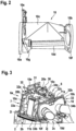
- Figure 3 shows the engine deck 6a of Figure 1 , which is part of the aircraft upper deck 6 of the helicopter 1 of Figure 1 and which forms the engine accommodating region 7 with the firewall arrangement 10 of Figure 1 and Figure 2 .
- the firewall arrangement 10 illustratively includes the front firewall 10a, the rear firewall 10b, the mid firewall 10c, the channel 10d, the upper extension 10e, and the rear cover 10f according to Figure 2 , while the gasket 10g is not visible in Figure 3 .
- the engine deck 6a is arranged above the fuselage 2 of Figure 1 .
- the front and rear firewalls 10a, 10b delimit the engine deck 6a, i. e. the engine accommodating region 7, in longitudinal direction of the helicopter 1 of Figure 1 .
- the engine accommodating region 7 accommodates at least one aircraft engine within the firewall arrangement 10 such that the firewall arrangement 10 defines a fire proof separation at least between the at least one aircraft engine and the aircraft interior region (2a, 2b in Figure 1 ).
- the firewall arrangement 10 preferably defines a fire proof separation between the at least one aircraft engine and other adjacent aircraft regions.
- Such other adjacent aircraft regions include the aircraft interior region (2a, 2b in Figure 1 ), as well as e. g. an engine compartment(s) of a further aircraft engine(s), and forward and aft regions to the engine accommodating region 7, such as e. g. gearbox or exhaust accommodating regions.
- the engine accommodating region 7 accommodates two aircraft engines 11a, 11b within the firewall arrangement 10, which are separated from each other by means of the mid firewall 10c of the firewall arrangement 10.
- Each aircraft engine 11a, 11b is preferably arranged in an associated engine compartment 20a, 20b.
- two adjacent engine compartments 20a, 20b are provided and the aircraft engine 11a is arranged in the engine compartment 20a and the aircraft engine 11b is arranged in the engine compartment 20b.
- the two aircraft engines 11a, 11b are embodied as air breathing propulsion gas turbines, which combust a fuel/air mix for power generation.
- each aircraft engine 11a, 11b is preferably mounted to associated engine mounts provided in the associated engine compartment 20a, 20b.
- the aircraft engines 11a, 11b and the associated engine mounts are not described in detail.
- the aircraft engines 11a, 11b and the associated engine mounts may be implemented by engines and engine mounts that are well-known to the person skilled in the art so that a detailed description thereof can be omitted, for brevity and conciseness.
- the two aircraft engines 11a, 11b and, thus, the two adjacent engine compartments 20a, 20b are covered by the cowling 8 of Figure 1 in mounted state of the cowling 8.
- the cowling 8 is not shown for illustrating a dismounted state of the cowling 8, which may e. g. be required to enable removal of one of the two aircraft engines 11a, 11b from its associated engine compartment 20a, 20b.
- the firewall arrangement 10 requires a stiffening support in order to prevent besides others damage to the firewall arrangement 10 during the maintenance phase.
- such a stiffening support may be provided by means of a stiffener skeleton 30.
- Illustrative realizations of the stiffener skeleton 30 are described in detail below at Figure 4 to Figure 7 .
- the stiffener skeleton 30 is configured to be mounted to the engine deck 6a and, more generally, to the aircraft upper deck 6 in a maintenance phase.
- the stiffener skeleton 30 is removed from the aircraft upper deck 6 after the maintenance phase and is, thus, not permanently installed on the aircraft upper deck 6.
- the stiffener skeleton 30 preferably comprises at least an upper stiffening structure 32 with a plurality of supporting arms 32a, 32b, 32c for providing upside stiffening support, and a lateral stiffening structure 33 with a plurality of supporting legs 33a, 33b, 34a, 34b for providing lateral stiffening support.
- the supporting legs 33a, 33b, 34a, 34b are intended to provide lateral stiffening support, they are also referred to as the "lateral supporting legs 33a, 33b, 34a, 34b".
- the stiffener skeleton 30 may further comprise an extension supporting arm 31 that is connected to one of the plurality of supporting arms 32a, 32b, 32c, illustratively to the supporting arm 32c.
- the extension supporting arm 31 forms a stiffening support for the upper extension 10e of the firewall arrangement 10.
- the lateral supporting legs 33a, 34a and the supporting arm 32a form a stiffening support for the front firewall 10a of the firewall arrangement 10
- the lateral supporting legs 33b, 34b and the supporting arm 32b form a stiffening support for the rear firewall 10b of the firewall arrangement 10.
- the supporting arm 32c forms a stiffening support for the mid firewall 10c of the firewall arrangement.
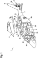
- Figure 4 shows the stiffener skeleton 30 of Figure 3 with the upper stiffening structure 32 and the lateral stiffening structure 33.
- the upper stiffening structure 32 has the plurality of supporting arms 32a, 32b, 32c and the lateral stiffening structure 33 has the plurality of lateral supporting legs 33a, 33b, 34a, 34b.
- the plurality of supporting arms 32a, 32b, 32c and the plurality of lateral supporting legs 33a, 33b, 34a, 34b form a self-supporting frame structure 40.
- this self-supporting frame structure 40 is configured to be arranged in a maintenance phase on the firewall arrangement 10 provided on the upper deck 6 of the rotary wing aircraft 1 of Figure 1 for supporting and stiffening at least the front firewall 10a, the rear firewall 10b and the mid firewall 10c of the firewall arrangement 10 of Figure 1 to Figure 3 .
- suitable mounting means 36a, 36b, 36c, 36d may be provided. These mounting means 36a, 36b, 36c, 36d are preferably configured to be fixedly mounted to associated fixation means, such as e. g. already existing engine mounts, provided at the upper deck 6 of the rotary wing aircraft 1.
- the mounting means 36a, 36b, 36c, 36d are integrated into the plurality of lateral supporting legs 33a, 33b, 34a, 34b.
- At least two of the plurality of lateral supporting legs 33a, 34a, 33b, 34b and an associated one of the plurality of supporting arms 32a, 32b, 32c form a C- or U-shaped skeleton section.
- the lateral supporting legs 33a, 34a and the supporting arm 32a form a front skeleton section 37
- the lateral supporting legs 33b, 34b and the supporting arm 32b form a rear skeleton section 38.
- the front skeleton section 37 is connected to the rear skeleton 38 via the supporting arm 32c.
- the front and rear skeleton sections 37, 38 are preferably C- or U-shaped.
- the supporting arms 32a, 32b are connected to each other by means of the supporting arm 32c.
- the supporting arms 32a, 32b, 32c illustratively form an H-shaped structure.
- the front and rear skeleton sections 37, 38 are likewise connected to each other.
- two optional lower linking arms 35a, 35b of the stiffener skeleton 30 preferably interconnect associated lateral supporting legs of the plurality of lateral supporting legs 33a, 33b, 34a, 34b.
- the optional lower linking arm 35a interconnects the lateral supporting legs 33a, 33b
- the optional lower linking arm 35b interconnects the lateral supporting legs 34a, 34b.
- the stiffener skeleton 30 further comprises the extension supporting arm 31 of Figure 3 . As described above, the extension supporting arm 31 is connected to the supporting arm 32c.
- At least the extension supporting arm 31, the supporting arms 32a, 32b, 32c and the lateral supporting legs 33a, 33b, 34a, 34b, but preferentially also the optional lower linking arms 35a, 35b and the mounting means 36a, 36b, 36c, 36d, are formed by rods, bars or beams. They may be made from any material that is suitable for stiffening and rigidifying at least the firewall arrangement 10 of Figure 1 to Figure 3 , such as e. g. metal or steel.
- At least the extension supporting arm 31, the supporting arms 32a, 32b, 32c and the lateral supporting legs 33a, 33b, 34a, 34b, but preferentially also the optional lower linking arms 35a, 35b and the mounting means 36a, 36b, 36c, 36d, are durably mounted to each other in an assembled state of the stiffener skeleton 30, i. e. rigidly attached to or integrally formed with each other to build up the self-supporting frame structure 40 such that at least a quick and easy disassembling of the stiffener skeleton 30 is disabled.
- at least a partial quick and easy disassembling and/or folding of the stiffener skeleton 30 may be enabled, e. g. when the stiffener skeleton 30 is not in use or for transportation purposes, as explained by way of example below at Figure 5 to Figure 7 .
- Figure 5 shows the stiffener skeleton 30 of Figure 4 with the extension supporting arm 31, the upper stiffening structure 32 having the plurality of supporting arms 32a, 32b, 32c, the lateral stiffening structure 33 having the plurality of lateral supporting legs 33a, 33b, 34a, 34b, the lower linking arms 35a, 35b, and the mounting means 36a, 36b, 36c, 36d.
- the lower linking arms 35a, 35b are optional and may, thus, be omitted.
- the upper stiffening structure 32 is now detachably attached to the lateral stiffening structure 33 in the assembled state.
- the lower linking arms 35a, 35b are also detachably attached to the lateral stiffening structure 33.
- the detachable attachment of the upper stiffening structure 32 and the lower linking arms 35a, 35b to the lateral stiffening structure 33 is illustratively realized via a plurality of lateral supporting legs connections 43a, 43b, 44a, 44b and lower linking arms connections 47a, 47b, 48a, 48b.
- the upper stiffening structure 32 as such may now be disassembled. Therefore, the supporting arms 32a, 32b of the plurality of supporting arms 32a, 32b, 32c of the upper stiffening structure 32 are now detachably attached to the supporting arm 32c in the assembled state via associated upper supporting arms connections 41a, 41b. Similarly, the supporting arm 32c is now detachably attached to the extension supporting arm 31 via an upper supporting arms connection 41c.
- At least a quick and easy disassembling of the stiffener skeleton 30 is enabled by implementing at least the lateral supporting legs connections 43a, 43b, 44a, 44b as snap-fit or clip connections.
- the lower linking arms connections 47a, 47b, 48a, 48b and/or the upper supporting arms connections 41a, 41b, 41c may also be implemented as snap-fit or clip connections.
- the supporting arms 32a, 32b, 32c of the upper stiffening structure 32, the lateral supporting legs 33a, 33b, 34a, 34b of the lateral stiffening structure 33 and/or the lower linking arms 35a, 35b may be foldable, at least in a disassembled state of the stiffener skeleton 30. This may be achieved by providing the supporting arms 32a, 32b, 32c with associated upper supporting arms hinges 42a, 42b, 42c, the lateral supporting legs 33a, 33b, 34a, 34b with associated lateral supporting legs hinges 45a, 45b, 46a, 46b and/or the lower linking arms 35a, 35b with associated lower linking arms hinges 49a, 49b.
- Figure 6 shows the stiffener skeleton 30 of Figure 4 with the front and rear skeleton sections 37, 38.
- the stiffener skeleton 30 is formed with the extension supporting arm 31, the upper stiffening structure 32 having the plurality of supporting arms 32a, 32b, 32c, the lateral stiffening structure 33 having the plurality of lateral supporting legs 33a, 33b, 34a, 34b, the lower linking arms 35a, 35b, and the mounting means 36a, 36b, 36c, 36d.
- the lower linking arms 35a, 35b are optional and may, thus, be omitted.
- the stiffener skeleton 30, which forms the self-supporting frame structure 40 is now foldable in an assembled state of the stiffener skeleton 30.
- the supporting arm 32c is now preferably connected to the extension supporting arm 31 via an associated upper supporting arms hinge 42d, and to the supporting arms 32a, 32b via associated upper supporting arms hinges 42e, 42f, and is provided with the upper supporting arms hinge 42c according to Figure 5 .
- the lower linking arms 35a, 35b are now preferably connected to the lateral supporting legs 33a, 33b, 34a, 34b via associated lateral supporting legs hinges 45c, 45d, 46c, 46d, and they are provided with the lower linking arms hinges 49a, 49b according to Figure 5 .
- the extension supporting arm 31 By moving the extension supporting arm 31 in a direction indicated by an arrow 50 around the upper supporting arms hinge 42d, the extension supporting arm 31 is folded towards the supporting arm 32c. Furthermore, by moving the upper supporting arms hinge 42c in a direction indicated by an arrow 52 and the lower linking arms hinges 49a, 49b into a direction indicated by arrows 51, the rear skeleton section 38 is folded towards the front skeleton section 37.
- Figure 7 shows the stiffener skeleton 30 of Figure 4 with the front and rear skeleton sections 37, 38.
- the stiffener skeleton 30 is formed with the extension supporting arm 31, the upper stiffening structure 32 having the plurality of supporting arms 32a, 32b, 32c, the lateral stiffening structure 33 having the plurality of lateral supporting legs 33a, 33b, 34a, 34b, the lower linking arms 35a, 35b, and the mounting means 36a, 36b, 36c, 36d.
- the lower linking arms 35a, 35b are optional and may, thus, be omitted.
- the stiffener skeleton 30, which forms the self-supporting frame structure 40 is now again foldable in an assembled state of the stiffener skeleton 30. More specifically, the supporting arm 32c is now preferably connected to the extension supporting arm 31 via the associated upper supporting arms hinge 42d according to Figure 5 , and the lateral supporting legs 33a, 33b, 34a, 34b are now preferably connected to the supporting arms 32a, 32b via associated upper supporting arms hinges 42g, 42h, 42i, 42j.
- the extension supporting arm 31 By moving the extension supporting arm 31 in a direction indicated by the arrow 50 of Figure 6 around the upper supporting arms hinge 42d, the extension supporting arm 31 is folded towards the supporting arm 32c. Furthermore, by moving the lateral supporting legs 33a, 33b together with the lower linking arm 35a in a direction indicated by an arrow 53, the lateral supporting legs 33a, 33b and the lower linking arm 35a are folded towards the upper stiffening structure 32. Moreover, by moving the lateral supporting legs 34a, 34b together with the lower linking arm 35b in a direction indicated by an arrow 54, the lateral supporting legs 34a, 34b and the lower linking arm 35b are likewise folded towards the upper stiffening structure 32.
- a safety hook may be attached to the stiffener skeleton 30 of Figure 3 to Figure 7 to further secure the stiffener skeleton 30 e. g. during mounting on the firewall arrangement 10 of Figure 1 to Figure 3 .
- a suitable eye or lug may be mounted to the stiffener skeleton.
- the length of one or more of the plurality of supporting arms 32a, 32b, 32c of the upper stiffening structure 32 according to any one of Figure 3 to Figure 7 may be adjustable, e. g. using a suitable length adjustment device, and so on.
Landscapes
- Engineering & Computer Science (AREA)
- Aviation & Aerospace Engineering (AREA)
- Mechanical Engineering (AREA)
- Manufacturing & Machinery (AREA)
- Transportation (AREA)
- Tires In General (AREA)
- Body Structure For Vehicles (AREA)
- Structures Of Non-Positive Displacement Pumps (AREA)
- Bridges Or Land Bridges (AREA)
Claims (14)
- Ossature (30) de renforcement qui est configurée pour être montée sur un plancher supérieur (6) d'un aéronef à voilure tournante (1) lors d'une phase de maintenance et pour être démontée du plancher supérieur (6) après la phase de maintenance, comprenant :une structure de renforcement supérieure (32) avec une pluralité de bras de soutien (32a, 32b, 32c) pour apporter un soutien de renforcement supérieur ; etune structure de renforcement latérale (33) avec une pluralité de pieds de soutien (33a, 33b, 34a, 34b) pour apporter un soutien de renforcement latéral ;dans laquelle la pluralité de bras de soutien (32a, 32b, 32c) et la pluralité de pieds de soutien (33a, 33b, 34a, 34b) forment une structure (40) autoportante formant cadre;et dans laquelle la structure (40) autoportante formant cadre est configurée pour être disposée, lors de la phase de maintenance, sur un agencement (10) de cloison pare-feu prévu sur un plancher supérieur (6) d'un aéronef à voilure tournante (1) pour soutenir et renforcer au moins une cloison pare-feu avant (10a), une cloison pare-feu arrière (10b), et une cloison pare-feu centrale (10c) de l'agencement (10) de cloison pare-feu.
- Ossature (30) de renforcement selon la revendication 1, comprenant en outre des moyens de montage (36a, 36b, 36c, 36d) qui sont configurés pour être montés de façon fixe sur les moyens de fixation associés prévus sur un plancher supérieur (6) d'un aéronef à voilure tournante (1).
- Ossature (30) de renforcement selon la revendication 2, dans laquelle les moyens de montage (36a, 36b, 36c, 36d) sont intégrés dans la pluralité de pieds de soutien (33a, 33b, 34a, 34b).
- Ossature (30) de renforcement selon l'une quelconque des revendications précédentes, comprenant en outre des bras de liaison (35a, 35b) inférieurs qui raccordent entre eux les pieds de soutien (33a, 33b, 34a, 34b) associés de la pluralité de pieds de soutien (33a, 33b, 34a, 34b).
- Ossature (30) de renforcement selon l'une quelconque des revendications précédentes, dans laquelle la structure de renforcement supérieure (32) est fixée, de préférence de façon détachable, sur la structure de renforcement latérale (33) dans un état assemblé, en particulier au moyen de raccordements encliquetables ou à clips associés.
- Ossature (30) de renforcement selon l'une quelconque des revendications précédentes, dans laquelle la structure (40) autoportante formant cadre est pliable.
- Ossature (30) de renforcement selon l'une quelconque des revendications précédentes, comprenant en outre une pluralité de raccordements (43a, 43b, 44a, 44b) de pieds de soutien qui fixent de façon détachable la pluralité de pieds de soutien (33a, 33b, 34a, 34b) sur la pluralité de bras de soutien (32a, 32b, 32c) dans un état assemblé de l'ossature (30) de renforcement.
- Ossature (30) de renforcement selon la revendication 7, dans laquelle au moins un parmi la pluralité de pieds de soutien (33a, 33b, 34a, 34b) comprend une articulation (45a, 45b, 46a, 46b) associée qui permet le pliage dudit au moins un parmi la pluralité de pieds de soutien (33a, 33b, 34a, 34b), au moins dans un état démonté de l'ossature (30) de renforcement.
- Ossature (30) de renforcement selon la revendication 7 ou 8, dans laquelle au moins un parmi la pluralité de bras de soutien (32a, 32b, 32c) comprend une articulation (42a, 42b, 42c) associée qui permet le pliage dudit au moins un parmi la pluralité de bras de soutien (32a, 32b, 32c), au moins dans un état démonté de l'ossature (30) de renforcement.
- Ossature (30) de renforcement selon l'une quelconque des revendications 1 à 6, dans laquelle au moins un bras (32c) parmi la pluralité de bras de soutien comprend une articulation (42c) associée qui permet le pliage dudit au moins un bras (32c) parmi la pluralité de bras de soutien dans un état assemblé de l'ossature (30) de renforcement, et dans laquelle chacun des bras de liaison (35a, 35b) inférieurs comprend une articulation (49a, 49b) associée qui permet le pliage des bras de liaison (35a, 35b) inférieurs dans l'état assemblé de l'ossature (30) de renforcement.
- Ossature (30) de renforcement selon l'une quelconque des revendications 1 à 6, comprenant en outre une pluralité d'articulations (42g, 42h, 42i, 42j) qui raccordent à pivotement la pluralité de pieds de soutien (33a, 33b, 34a, 34b) à la pluralité de bras de soutien (32a, 32b, 32c) afin de permettre le pliage de la pluralité de pieds de soutien (33a, 33b, 34a, 34b) en direction de la pluralité de bras de soutien (32a, 32b, 32c) dans un état assemblé de l'ossature (30) de renforcement.
- Ossature (30) de renforcement selon l'une quelconque des revendications précédentes, dans laquelle au moins deux pieds parmi la pluralité de pieds de soutien (33a, 34a, 33b, 34b) et un bras associé parmi la pluralité de bras de soutien (32a, 32b) forment une partie (37, 38) d'ossature en forme de C ou de U.
- Ossature (30) de renforcement selon l'une quelconque des revendications précédentes, dans laquelle un premier et un deuxième pieds (33a, 34a) de la pluralité de pieds de soutien (33a, 33b, 34a, 34b) et un premier bras de soutien (32a) de la pluralité de bras de soutien (32a, 32b, 32c) forment une partie avant (37) d'ossature, dans laquelle un troisième et un quatrième pieds (33b, 34b) de la pluralité de pieds de soutien (33a, 33b, 34a, 34b) et un deuxième bras de soutien (32b) de la pluralité de bras de soutien (32a, 32b, 32c) forment une partie arrière (38) d'ossature, et dans laquelle un troisième bras de soutien (32c) de la pluralité de bras de soutien (32a, 32b, 32c) raccorde la partie avant (37) de l'ossature à la partie arrière (38) de l'ossature.
- Ossature (30) de renforcement selon l'une quelconque des revendications précédentes, comprenant en outre un bras de soutien pour prolongement (31) qui est raccordé à l'un (32c) parmi la pluralité de bras de soutien, en particulier au moyen d'une articulation (42d) associée.
Priority Applications (5)
| Application Number | Priority Date | Filing Date | Title |
|---|---|---|---|
| EP20400021.0A EP4001105B1 (fr) | 2020-11-20 | 2020-11-20 | Squelette de renfort pour un agencement de pare-feu d'un aéronef à voilure tournante |
| KR1020210076824A KR102555342B1 (ko) | 2020-11-20 | 2021-06-14 | 회전익 항공기의 방화벽 구조물 용 보강재 골격 |
| JP2021099310A JP7197635B2 (ja) | 2020-11-20 | 2021-06-15 | 回転翼航空機の防火壁配置のための補強材骨格 |
| US17/350,438 US11655017B2 (en) | 2020-11-20 | 2021-06-17 | Stiffener skeleton for a firewall arrangement of a rotary wing aircraft |
| CN202110705718.0A CN114590392B (zh) | 2020-11-20 | 2021-06-24 | 用于旋翼航空器的防火墙装置的加强骨架 |
Applications Claiming Priority (1)
| Application Number | Priority Date | Filing Date | Title |
|---|---|---|---|
| EP20400021.0A EP4001105B1 (fr) | 2020-11-20 | 2020-11-20 | Squelette de renfort pour un agencement de pare-feu d'un aéronef à voilure tournante |
Publications (2)
| Publication Number | Publication Date |
|---|---|
| EP4001105A1 EP4001105A1 (fr) | 2022-05-25 |
| EP4001105B1 true EP4001105B1 (fr) | 2023-07-05 |
Family
ID=74175585
Family Applications (1)
| Application Number | Title | Priority Date | Filing Date |
|---|---|---|---|
| EP20400021.0A Active EP4001105B1 (fr) | 2020-11-20 | 2020-11-20 | Squelette de renfort pour un agencement de pare-feu d'un aéronef à voilure tournante |
Country Status (5)
| Country | Link |
|---|---|
| US (1) | US11655017B2 (fr) |
| EP (1) | EP4001105B1 (fr) |
| JP (1) | JP7197635B2 (fr) |
| KR (1) | KR102555342B1 (fr) |
| CN (1) | CN114590392B (fr) |
Families Citing this family (2)
| Publication number | Priority date | Publication date | Assignee | Title |
|---|---|---|---|---|
| US12582853B2 (en) * | 2023-07-03 | 2026-03-24 | Textron Innovations Inc. | Fire zone thermal protection for adjacent components |
| CN117382890B (zh) * | 2023-10-24 | 2024-08-27 | 湖南山河华宇航空科技有限公司 | 航空发动机安装架及飞机 |
Family Cites Families (14)
| Publication number | Priority date | Publication date | Assignee | Title |
|---|---|---|---|---|
| US2989273A (en) * | 1956-10-17 | 1961-06-20 | Sud Aviation | Outfit for emplaning and servicing light helicopters |
| US3166277A (en) * | 1963-07-19 | 1965-01-19 | Hiller Aircraft Company Inc | Vehicle work platform |
| US3744743A (en) * | 1970-09-11 | 1973-07-10 | Gates Learjet Corp | Helicopter power plant system |
| US6138949A (en) | 1998-10-30 | 2000-10-31 | Sikorsky Aircraft Corporation | Main rotor pylon support structure |
| FR2904604B1 (fr) | 2006-08-04 | 2009-02-27 | Airbus France Sas | Element de structure d'un aeronef |
| FR2946621B1 (fr) | 2009-06-15 | 2013-02-08 | Aircelle Sa | Procede d'assemblage d'une protection thermique sur une structure interne fixe de nacelle de turboreacteur |
| US8733500B1 (en) | 2012-11-12 | 2014-05-27 | Hexcel Corporation | Acoustic structure with internal thermal regulators |
| FR3015431B1 (fr) | 2013-12-19 | 2017-12-15 | Airbus Operations Sas | Structure primaire de mat d'accrochage renforcee. |
| PL3056423T3 (pl) * | 2015-02-16 | 2018-04-30 | Airbus Helicopters Deutschland GmbH | Statek powietrzny z kadłubem, który wyznacza co najmniej obszar wewnętrzny i obszar mieszczący układ napędowy |
| EP3281861B1 (fr) * | 2016-08-11 | 2019-10-02 | AIRBUS HELICOPTERS DEUTSCHLAND GmbH | Aéronef à voilure tournante équipé d'un fuselage qui comprend au moins un panneau durci structurel |
| US10947904B2 (en) | 2016-12-07 | 2021-03-16 | Rohr, Inc. | Sealing cooling inner fixed structure |
| CN109941351B (zh) * | 2017-12-20 | 2020-12-11 | 广州汽车集团股份有限公司 | 发动机舱结构及车辆 |
| US10669038B2 (en) | 2018-04-20 | 2020-06-02 | Textron Innovations Inc. | Engine inlet system with integral firewall seal |
| PL3932801T3 (pl) * | 2020-06-30 | 2022-09-19 | Airbus Helicopters Deutschland GmbH | Wiropłat z układem przegrody przeciwogniowej |
-
2020
- 2020-11-20 EP EP20400021.0A patent/EP4001105B1/fr active Active
-
2021
- 2021-06-14 KR KR1020210076824A patent/KR102555342B1/ko active Active
- 2021-06-15 JP JP2021099310A patent/JP7197635B2/ja active Active
- 2021-06-17 US US17/350,438 patent/US11655017B2/en active Active
- 2021-06-24 CN CN202110705718.0A patent/CN114590392B/zh active Active
Also Published As
| Publication number | Publication date |
|---|---|
| JP2022082417A (ja) | 2022-06-01 |
| KR102555342B1 (ko) | 2023-07-12 |
| CN114590392B (zh) | 2024-05-24 |
| KR20220069791A (ko) | 2022-05-27 |
| US11655017B2 (en) | 2023-05-23 |
| EP4001105A1 (fr) | 2022-05-25 |
| JP7197635B2 (ja) | 2022-12-27 |
| US20220161915A1 (en) | 2022-05-26 |
| CN114590392A (zh) | 2022-06-07 |
Similar Documents
| Publication | Publication Date | Title |
|---|---|---|
| US8573531B2 (en) | Airplane with rear engines | |
| CA3050051C (fr) | Un helicoptere compose equipe d'un arrangement de voilure fixe | |
| CA3148165C (fr) | Aeronef a voilure tournante comportant une configuration de coupe-feu | |
| US5377934A (en) | Helicopter conversion | |
| EP3411293B1 (fr) | Aéronef modulaire | |
| US9533768B2 (en) | Aircraft engine mounting system | |
| US9751619B1 (en) | Remotely controlled co-axial rotorcraft for heavy-lift aerial-crane operations | |
| EP2933187B1 (fr) | Aéronef à voilure tournante avec une queue à poutres multiples | |
| US9738379B2 (en) | Removable lift assembly for a rotorcraft, and a rotorcraft | |
| EP4001105B1 (fr) | Squelette de renfort pour un agencement de pare-feu d'un aéronef à voilure tournante | |
| US10112707B1 (en) | Remotely controlled co-axial rotorcraft for heavy-lift aerial-crane operations | |
| US11820485B2 (en) | Rotary wing aircraft with a firewall arrangement | |
| RU2657650C1 (ru) | Рама мультикоптера (варианты) | |
| EP3556661B1 (fr) | Système d'entrée de moteur avec joint coupe-feu integral | |
| US12258121B2 (en) | Rotary wing aircraft with a firewall arrangement having at least one funnel-shaped lower firewall | |
| US20210229794A1 (en) | Vehicle with at least one emergency exit system | |
| RU2693362C1 (ru) | Летательный аппарат горизонтального полёта с вертикальным взлётом и посадкой и несущая платформа для летательного аппарата горизонтального полёта с вертикальным взлётом и посадкой | |
| EP4717585A1 (fr) | Aéronef à voilure tournante avec un fuselage qui comprend une structure de coque de support de charge et une structure d'élément de raidissement de support de charge | |
| WO2012102640A2 (fr) | Cellule d'avion à très haute maniabilité à régimes multiples | |
| RU2844699C1 (ru) | Конвертоплан модульный | |
| RU2844699C9 (ru) | Конвертоплан модульный | |
| RU2806918C1 (ru) | Сверхлегкий или легкий летательный аппарат вертолетного типа модульной конструкции |
Legal Events
| Date | Code | Title | Description |
|---|---|---|---|
| PUAI | Public reference made under article 153(3) epc to a published international application that has entered the european phase |
Free format text: ORIGINAL CODE: 0009012 |
|
| STAA | Information on the status of an ep patent application or granted ep patent |
Free format text: STATUS: THE APPLICATION HAS BEEN PUBLISHED |
|
| STAA | Information on the status of an ep patent application or granted ep patent |
Free format text: STATUS: REQUEST FOR EXAMINATION WAS MADE |
|
| AK | Designated contracting states |
Kind code of ref document: A1 Designated state(s): AL AT BE BG CH CY CZ DE DK EE ES FI FR GB GR HR HU IE IS IT LI LT LU LV MC MK MT NL NO PL PT RO RS SE SI SK SM TR |
|
| 17P | Request for examination filed |
Effective date: 20220429 |
|
| RBV | Designated contracting states (corrected) |
Designated state(s): AL AT BE BG CH CY CZ DE DK EE ES FI FR GB GR HR HU IE IS IT LI LT LU LV MC MK MT NL NO PL PT RO RS SE SI SK SM TR |
|
| GRAP | Despatch of communication of intention to grant a patent |
Free format text: ORIGINAL CODE: EPIDOSNIGR1 |
|
| STAA | Information on the status of an ep patent application or granted ep patent |
Free format text: STATUS: GRANT OF PATENT IS INTENDED |
|
| INTG | Intention to grant announced |
Effective date: 20230329 |
|
| RIN1 | Information on inventor provided before grant (corrected) |
Inventor name: THE OTHER INVENTORS HAVE WAIVED THEIR RIGHT TO BE THUS MENTIONED. Inventor name: ARNOULD, PIERRE Inventor name: KAMMERER, MARKUS Inventor name: NEUKIRCH, HUBERT Inventor name: GESTER, MATHIEU Inventor name: MONTIL, NICOLAS Inventor name: VAYSSIERE, AURELIEN |
|
| GRAS | Grant fee paid |
Free format text: ORIGINAL CODE: EPIDOSNIGR3 |
|
| GRAA | (expected) grant |
Free format text: ORIGINAL CODE: 0009210 |
|
| STAA | Information on the status of an ep patent application or granted ep patent |
Free format text: STATUS: THE PATENT HAS BEEN GRANTED |
|
| AK | Designated contracting states |
Kind code of ref document: B1 Designated state(s): AL AT BE BG CH CY CZ DE DK EE ES FI FR GB GR HR HU IE IS IT LI LT LU LV MC MK MT NL NO PL PT RO RS SE SI SK SM TR |
|
| P01 | Opt-out of the competence of the unified patent court (upc) registered |
Effective date: 20230530 |
|
| REG | Reference to a national code |
Ref country code: CH Ref legal event code: EP |
|
| REG | Reference to a national code |
Ref country code: AT Ref legal event code: REF Ref document number: 1584633 Country of ref document: AT Kind code of ref document: T Effective date: 20230715 |
|
| REG | Reference to a national code |
Ref country code: DE Ref legal event code: R096 Ref document number: 602020013288 Country of ref document: DE |
|
| REG | Reference to a national code |
Ref country code: IE Ref legal event code: FG4D |
|
| REG | Reference to a national code |
Ref country code: LT Ref legal event code: MG9D |
|
| REG | Reference to a national code |
Ref country code: NL Ref legal event code: MP Effective date: 20230705 |
|
| REG | Reference to a national code |
Ref country code: AT Ref legal event code: MK05 Ref document number: 1584633 Country of ref document: AT Kind code of ref document: T Effective date: 20230705 |
|
| PG25 | Lapsed in a contracting state [announced via postgrant information from national office to epo] |
Ref country code: NL Free format text: LAPSE BECAUSE OF FAILURE TO SUBMIT A TRANSLATION OF THE DESCRIPTION OR TO PAY THE FEE WITHIN THE PRESCRIBED TIME-LIMIT Effective date: 20230705 |
|
| PG25 | Lapsed in a contracting state [announced via postgrant information from national office to epo] |
Ref country code: ES Free format text: LAPSE BECAUSE OF FAILURE TO SUBMIT A TRANSLATION OF THE DESCRIPTION OR TO PAY THE FEE WITHIN THE PRESCRIBED TIME-LIMIT Effective date: 20230705 |
|
| PG25 | Lapsed in a contracting state [announced via postgrant information from national office to epo] |
Ref country code: IS Free format text: LAPSE BECAUSE OF FAILURE TO SUBMIT A TRANSLATION OF THE DESCRIPTION OR TO PAY THE FEE WITHIN THE PRESCRIBED TIME-LIMIT Effective date: 20231105 |
|
| PG25 | Lapsed in a contracting state [announced via postgrant information from national office to epo] |
Ref country code: SE Free format text: LAPSE BECAUSE OF FAILURE TO SUBMIT A TRANSLATION OF THE DESCRIPTION OR TO PAY THE FEE WITHIN THE PRESCRIBED TIME-LIMIT Effective date: 20230705 Ref country code: RS Free format text: LAPSE BECAUSE OF FAILURE TO SUBMIT A TRANSLATION OF THE DESCRIPTION OR TO PAY THE FEE WITHIN THE PRESCRIBED TIME-LIMIT Effective date: 20230705 Ref country code: PT Free format text: LAPSE BECAUSE OF FAILURE TO SUBMIT A TRANSLATION OF THE DESCRIPTION OR TO PAY THE FEE WITHIN THE PRESCRIBED TIME-LIMIT Effective date: 20231106 Ref country code: NO Free format text: LAPSE BECAUSE OF FAILURE TO SUBMIT A TRANSLATION OF THE DESCRIPTION OR TO PAY THE FEE WITHIN THE PRESCRIBED TIME-LIMIT Effective date: 20231005 Ref country code: LV Free format text: LAPSE BECAUSE OF FAILURE TO SUBMIT A TRANSLATION OF THE DESCRIPTION OR TO PAY THE FEE WITHIN THE PRESCRIBED TIME-LIMIT Effective date: 20230705 Ref country code: LT Free format text: LAPSE BECAUSE OF FAILURE TO SUBMIT A TRANSLATION OF THE DESCRIPTION OR TO PAY THE FEE WITHIN THE PRESCRIBED TIME-LIMIT Effective date: 20230705 Ref country code: IS Free format text: LAPSE BECAUSE OF FAILURE TO SUBMIT A TRANSLATION OF THE DESCRIPTION OR TO PAY THE FEE WITHIN THE PRESCRIBED TIME-LIMIT Effective date: 20231105 Ref country code: HR Free format text: LAPSE BECAUSE OF FAILURE TO SUBMIT A TRANSLATION OF THE DESCRIPTION OR TO PAY THE FEE WITHIN THE PRESCRIBED TIME-LIMIT Effective date: 20230705 Ref country code: FI Free format text: LAPSE BECAUSE OF FAILURE TO SUBMIT A TRANSLATION OF THE DESCRIPTION OR TO PAY THE FEE WITHIN THE PRESCRIBED TIME-LIMIT Effective date: 20230705 Ref country code: ES Free format text: LAPSE BECAUSE OF FAILURE TO SUBMIT A TRANSLATION OF THE DESCRIPTION OR TO PAY THE FEE WITHIN THE PRESCRIBED TIME-LIMIT Effective date: 20230705 Ref country code: AT Free format text: LAPSE BECAUSE OF FAILURE TO SUBMIT A TRANSLATION OF THE DESCRIPTION OR TO PAY THE FEE WITHIN THE PRESCRIBED TIME-LIMIT Effective date: 20230705 |
|
| PG25 | Lapsed in a contracting state [announced via postgrant information from national office to epo] |
Ref country code: PL Free format text: LAPSE BECAUSE OF FAILURE TO SUBMIT A TRANSLATION OF THE DESCRIPTION OR TO PAY THE FEE WITHIN THE PRESCRIBED TIME-LIMIT Effective date: 20230705 |
|
| REG | Reference to a national code |
Ref country code: DE Ref legal event code: R097 Ref document number: 602020013288 Country of ref document: DE |
|
| PG25 | Lapsed in a contracting state [announced via postgrant information from national office to epo] |
Ref country code: SM Free format text: LAPSE BECAUSE OF FAILURE TO SUBMIT A TRANSLATION OF THE DESCRIPTION OR TO PAY THE FEE WITHIN THE PRESCRIBED TIME-LIMIT Effective date: 20230705 Ref country code: RO Free format text: LAPSE BECAUSE OF FAILURE TO SUBMIT A TRANSLATION OF THE DESCRIPTION OR TO PAY THE FEE WITHIN THE PRESCRIBED TIME-LIMIT Effective date: 20230705 Ref country code: EE Free format text: LAPSE BECAUSE OF FAILURE TO SUBMIT A TRANSLATION OF THE DESCRIPTION OR TO PAY THE FEE WITHIN THE PRESCRIBED TIME-LIMIT Effective date: 20230705 Ref country code: DK Free format text: LAPSE BECAUSE OF FAILURE TO SUBMIT A TRANSLATION OF THE DESCRIPTION OR TO PAY THE FEE WITHIN THE PRESCRIBED TIME-LIMIT Effective date: 20230705 Ref country code: CZ Free format text: LAPSE BECAUSE OF FAILURE TO SUBMIT A TRANSLATION OF THE DESCRIPTION OR TO PAY THE FEE WITHIN THE PRESCRIBED TIME-LIMIT Effective date: 20230705 Ref country code: SK Free format text: LAPSE BECAUSE OF FAILURE TO SUBMIT A TRANSLATION OF THE DESCRIPTION OR TO PAY THE FEE WITHIN THE PRESCRIBED TIME-LIMIT Effective date: 20230705 |
|
| PLBE | No opposition filed within time limit |
Free format text: ORIGINAL CODE: 0009261 |
|
| STAA | Information on the status of an ep patent application or granted ep patent |
Free format text: STATUS: NO OPPOSITION FILED WITHIN TIME LIMIT |
|
| 26N | No opposition filed |
Effective date: 20240408 |
|
| PG25 | Lapsed in a contracting state [announced via postgrant information from national office to epo] |
Ref country code: MC Free format text: LAPSE BECAUSE OF FAILURE TO SUBMIT A TRANSLATION OF THE DESCRIPTION OR TO PAY THE FEE WITHIN THE PRESCRIBED TIME-LIMIT Effective date: 20230705 |
|
| PG25 | Lapsed in a contracting state [announced via postgrant information from national office to epo] |
Ref country code: LU Free format text: LAPSE BECAUSE OF NON-PAYMENT OF DUE FEES Effective date: 20231120 |
|
| PG25 | Lapsed in a contracting state [announced via postgrant information from national office to epo] |
Ref country code: MC Free format text: LAPSE BECAUSE OF FAILURE TO SUBMIT A TRANSLATION OF THE DESCRIPTION OR TO PAY THE FEE WITHIN THE PRESCRIBED TIME-LIMIT Effective date: 20230705 Ref country code: LU Free format text: LAPSE BECAUSE OF NON-PAYMENT OF DUE FEES Effective date: 20231120 Ref country code: SI Free format text: LAPSE BECAUSE OF FAILURE TO SUBMIT A TRANSLATION OF THE DESCRIPTION OR TO PAY THE FEE WITHIN THE PRESCRIBED TIME-LIMIT Effective date: 20230705 |
|
| REG | Reference to a national code |
Ref country code: BE Ref legal event code: MM Effective date: 20231130 |
|
| REG | Reference to a national code |
Ref country code: IE Ref legal event code: MM4A |
|
| PG25 | Lapsed in a contracting state [announced via postgrant information from national office to epo] |
Ref country code: IE Free format text: LAPSE BECAUSE OF NON-PAYMENT OF DUE FEES Effective date: 20231120 |
|
| PG25 | Lapsed in a contracting state [announced via postgrant information from national office to epo] |
Ref country code: BE Free format text: LAPSE BECAUSE OF NON-PAYMENT OF DUE FEES Effective date: 20231130 |
|
| PG25 | Lapsed in a contracting state [announced via postgrant information from national office to epo] |
Ref country code: IE Free format text: LAPSE BECAUSE OF NON-PAYMENT OF DUE FEES Effective date: 20231120 Ref country code: BE Free format text: LAPSE BECAUSE OF NON-PAYMENT OF DUE FEES Effective date: 20231130 |
|
| PG25 | Lapsed in a contracting state [announced via postgrant information from national office to epo] |
Ref country code: BG Free format text: LAPSE BECAUSE OF FAILURE TO SUBMIT A TRANSLATION OF THE DESCRIPTION OR TO PAY THE FEE WITHIN THE PRESCRIBED TIME-LIMIT Effective date: 20230705 |
|
| PG25 | Lapsed in a contracting state [announced via postgrant information from national office to epo] |
Ref country code: BG Free format text: LAPSE BECAUSE OF FAILURE TO SUBMIT A TRANSLATION OF THE DESCRIPTION OR TO PAY THE FEE WITHIN THE PRESCRIBED TIME-LIMIT Effective date: 20230705 |
|
| GBPC | Gb: european patent ceased through non-payment of renewal fee |
Effective date: 20241120 |
|
| PG25 | Lapsed in a contracting state [announced via postgrant information from national office to epo] |
Ref country code: CY Free format text: LAPSE BECAUSE OF FAILURE TO SUBMIT A TRANSLATION OF THE DESCRIPTION OR TO PAY THE FEE WITHIN THE PRESCRIBED TIME-LIMIT; INVALID AB INITIO Effective date: 20201120 |
|
| PG25 | Lapsed in a contracting state [announced via postgrant information from national office to epo] |
Ref country code: HU Free format text: LAPSE BECAUSE OF FAILURE TO SUBMIT A TRANSLATION OF THE DESCRIPTION OR TO PAY THE FEE WITHIN THE PRESCRIBED TIME-LIMIT; INVALID AB INITIO Effective date: 20201120 |
|
| PG25 | Lapsed in a contracting state [announced via postgrant information from national office to epo] |
Ref country code: GR Free format text: LAPSE BECAUSE OF FAILURE TO SUBMIT A TRANSLATION OF THE DESCRIPTION OR TO PAY THE FEE WITHIN THE PRESCRIBED TIME-LIMIT; INVALID AB INITIO Effective date: 20201120 |
|
| PG25 | Lapsed in a contracting state [announced via postgrant information from national office to epo] |
Ref country code: GB Free format text: LAPSE BECAUSE OF NON-PAYMENT OF DUE FEES Effective date: 20241120 |
|
| REG | Reference to a national code |
Ref country code: CH Ref legal event code: U11 Free format text: ST27 STATUS EVENT CODE: U-0-0-U10-U11 (AS PROVIDED BY THE NATIONAL OFFICE) Effective date: 20251201 |
|
| PG25 | Lapsed in a contracting state [announced via postgrant information from national office to epo] |
Ref country code: TR Free format text: LAPSE BECAUSE OF FAILURE TO SUBMIT A TRANSLATION OF THE DESCRIPTION OR TO PAY THE FEE WITHIN THE PRESCRIBED TIME-LIMIT Effective date: 20230705 |
|
| PGFP | Annual fee paid to national office [announced via postgrant information from national office to epo] |
Ref country code: DE Payment date: 20251119 Year of fee payment: 6 |
|
| PGFP | Annual fee paid to national office [announced via postgrant information from national office to epo] |
Ref country code: IT Payment date: 20251125 Year of fee payment: 6 |
|
| PGFP | Annual fee paid to national office [announced via postgrant information from national office to epo] |
Ref country code: FR Payment date: 20251126 Year of fee payment: 6 |
|
| PGFP | Annual fee paid to national office [announced via postgrant information from national office to epo] |
Ref country code: CH Payment date: 20251201 Year of fee payment: 6 |