EP4001109A1 - Raumantriebsvorrichtung ohne materialausstoss unter verwendung der kräfte, die auf der höhe eines satzes von schubkörpern erzeugt werden, die in einem hermetisch geschlossenen kreislauf auf dem weg einer sich bewegenden flüssigkeit angeordnet sind - Google Patents
Raumantriebsvorrichtung ohne materialausstoss unter verwendung der kräfte, die auf der höhe eines satzes von schubkörpern erzeugt werden, die in einem hermetisch geschlossenen kreislauf auf dem weg einer sich bewegenden flüssigkeit angeordnet sind Download PDFInfo
- Publication number
- EP4001109A1 EP4001109A1 EP20208716.9A EP20208716A EP4001109A1 EP 4001109 A1 EP4001109 A1 EP 4001109A1 EP 20208716 A EP20208716 A EP 20208716A EP 4001109 A1 EP4001109 A1 EP 4001109A1
- Authority
- EP
- European Patent Office
- Prior art keywords
- thrust
- thruster
- fluid
- flow
- wing
- Prior art date
- Legal status (The legal status is an assumption and is not a legal conclusion. Google has not performed a legal analysis and makes no representation as to the accuracy of the status listed.)
- Withdrawn
Links
Images






Classifications
-
- B—PERFORMING OPERATIONS; TRANSPORTING
- B64—AIRCRAFT; AVIATION; COSMONAUTICS
- B64G—COSMONAUTICS; VEHICLES OR EQUIPMENT THEREFOR
- B64G1/00—Cosmonautic vehicles
- B64G1/22—Parts of, or equipment specially adapted for fitting in or to, cosmonautic vehicles
- B64G1/40—Arrangements or adaptations of propulsion systems
- B64G1/411—Electric propulsion
-
- B—PERFORMING OPERATIONS; TRANSPORTING
- B64—AIRCRAFT; AVIATION; COSMONAUTICS
- B64C—AEROPLANES; HELICOPTERS
- B64C39/00—Aircraft not otherwise provided for
- B64C39/003—Aircraft not otherwise provided for with wings, paddle wheels, bladed wheels, moving or rotating in relation to the fuselage
- B64C39/005—Aircraft not otherwise provided for with wings, paddle wheels, bladed wheels, moving or rotating in relation to the fuselage about a horizontal transversal axis
Definitions
- This spatial propulsion device does not reject material and therefore does not need to have a reservoir of material to be ejected. Its operation is based on the physical operating principles of a closed circuit fluid circulation wind tunnel. Unlike this one which is immobile and has the function of studying the impact of the forces generated by the flow of a fluid around an object of study, which can be a scale model of a wing of In an airplane, for example, said thruster exploits these forces to move in a straight line, change direction or perform a rotation.
- the object of study in a wind tunnel becomes the thrust body in said thruster. It can be of different types: a wing (6), a rotating object with axial symmetry (7) or a combination of these two elements (8).
- the relative movement of the air in relation to an aircraft wing mainly generates two important aerodynamic forces. These forces are composed of a force of lift, or lift, perpendicular to the direction of the flow of the air current and which maintains the plane in the air, and a drag force which opposes its movement.
- wings are not limited to aerodynamics, some boats also use wings, which are called foils in the world of maritime navigation. These foils are positioned and profiled in such a way as to generate hydrodynamic lift capable of lifting the hull of the boat partially or totally out of the water, thus reducing its drag.
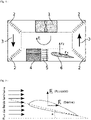
- a closed-circuit fluid circulation wind tunnel whose object of study is a scale model of an airplane wing is the seat of a set of forces including lift (Fz), drag (Fx) and torque induced rotation (Fi), as indicated on the fig. 1 .
- Two wind tunnel modules of this type can be combined to neutralize the drag and rotation forces two by two as shown in the figure. fig. 10 , and keep only the two thrust forces which are added in this case.
- Thrust and drift forces are two forces generated by the presence of a thrust body, which can be a wing, an axially symmetric rotating object (e.g. a Flettner rotor using the Magnus effect) or a combination of the two previous elements, placed in a flow of fluid. All these forces are at the origin of the different movements that the thruster can perform.
- the thrust is all the more important as the fluid is denser.
- the wing grows more or less depending on its wing surface, its camber, its angle of attack or the possible use of devices equivalent to the high lift found on certain aircraft wings.
- the fig. 15 displays a thruster using wings with a large wing area.
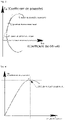
- the Cz/Cx ratio is called fineness.
- the point P2 of maximum glide ratio on the curve of the fig. 3 corresponds to the optimal operating mode of the thruster for which the maximum power is used by the thrust.
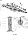
- the coefficients Cz and Cx depend on the presence or not of discs on the rotor like those shown at the ends of the cylinder of the fig. 6 . Moreover, we can put several at regular intervals or not throughout the rotor, which considerably improves the thrust of this one.
- This thrust body has the particularity of diametrically changing the direction of thrust when the direction of rotation of the rotor is reversed, which is practical for slowing down, stopping and restarting the thruster in the opposite direction, for example.
- the fig. 7 illustrates a cylinder accelerating only the relative flow on the upper surface of the wing.
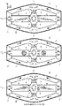
- the fig. 8 displays three examples of wind tunnels, each using a different type of thrust body: a wing (6), an axially symmetric rotating object (7) and a combination of these two elements (8).
- the thrust Fz Three main forces appear when this thruster is in operation; the thrust Fz, the drift Fx and an induced rotational force whose direction is opposite to that of the circulation of the fluid in the ducts, according to Newton's action-reaction principle.
- the overall movement is of the spiral type and results from two rectilinear forces Fz, Fx and a third rotating one Fi, which does not allow going in a straight line from point A to point B.
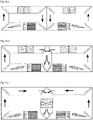
- the thruster configuration on the fig. 9.c is an evolution of the configuration on the fig. 9.a through the configuration on the fig. 9.b .
- Each of these configurations allows us to control to a certain extent the rotational force Fi and those of the drift Fx and the thrust by acting on the difference in the flow rate of the fluid in the two loops of the thruster.
- the two loops of each of the configurations are symmetrical with respect to the YZ plane and the thruster movements limited to the XZ plane.
- this one is limited to the double rectangular two-dimensional thruster ( fig. 9 , 10 and 13.a ) to illustrate the use of the physical principles of the operation of a more or less complex wind tunnel in closed circuit to produce a space thruster.
- the configurations and shapes of thrusters that can be made are numerous, here are some variants:
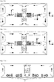
- the fig. 16.a and 16.b are configurations of direction changes made by a quadruple rectangle two-dimensional thruster. Directions clockwise or counterclockwise are considered to be given with respect to an observer always looking at the thruster from the same side of the XZ plane.
- Each configuration has two wings of symmetrical biconvex profile. The direction of a wing's thrust depends on the sign of its angle of attack relative to the laminar flow of the incident fluid. The wings in the configuration fig.
- 16.a are oriented in such a way as to apply a couple of forces Fzg and Fzd making it possible to rotate the thruster in the direction of rotation of the needles of a clock with respect to the observer.
- those of the fig. 16.b rotate it in the opposite direction.
- the ship can perform different actions and movements such as starting, moving in a straight line, changing direction, slowing down, stopping and going in the opposite direction. It suffices for this to apply to the pair of wings a succession of changes of angles of attack to obtain the succession of actions and movements desired.
- the semi-circular and circular thrusters are specific configurations respectively of double and quadruple rectangle thrusters whose elbows are not at right angles but in an arc of a circle.
- the fig. 15.a and 15.b feature a twin-rectangle thruster with oversized wings to increase overall thrust.
- This one has three conditioners (9) comprising partitions (10) enabling it to distribute the outgoing flows (3b) arriving on the wings in a uniform manner over the entire length of the leading edges.
- the inflows (3a) in the conditioners (9) may not be uniform since they do not act directly on the wings.
- the fig. 17.a gives an example of a thruster using two rotating cylinders (7) on either side of the plane of symmetry to create thrusts thanks to the Magnus effect.
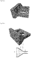
- the fig. 17.b gives a 3D view of the thruster which is high to hold the Flettner rotors. This height is adaptable, as for the wings, depending on the level of thrust you want to obtain.
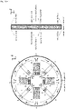
- the thruster of the fig.18.a is of two-dimensional type and comprises four thrust bodies of the aircraft wing type (6) which are placed in the same plane according to the arrangement of the cardinal points. This arrangement gives said thruster the ability to orient its movements in all directions in space.
- the actions of changing directions, starting, accelerating, decelerating and stopping are done with a simple change of orientation of the wings relative to the thruster plane.
- the actions and movements therefore correspond to very precise combinations of the orientation of the wings with respect to each other, and with respect to the plane of the thruster.
- the circular shape of said propellant allows it to be inserted into spacecraft which are for the most part cylindrical in shape, therefore with a circular section.
- the arrows on the section view in the YZ plane of the fig. 18.a give the directions of the movements that the thruster can take.
- the fig. 18.b gives an example of a three-dimensional version of the thruster, showing two sections, one in the XY plane and the other in the YZ plane. The direction of thrust is always taken in the increasing direction of the Z axis.
- the figures ranging from 19 to 22 give the 3D views of examples of thrusters of the two-dimensional type which are respectively; the semicircular, circular, double rectangle, quadruple rectangle and quadruple rectangle with oversized wings ( fig. 22.b ).
- the figures ranging from 23 to 26 give the 3D views of examples of thrusters of the three-dimensional type which are respectively; the semicircular, circular, double rectangle and quadruple rectangle.
- the variants of the thruster mentioned above remain simple variants, but one can very well add mechanical and electromechanical elements inside the thrusters to act on the level and the direction of one or more physical parameters or to give more degree of freedom to the thrust bodies to allow movement throughout the space.
- the combinations are numerous, the only constant being that the fluid circulates around one or more thrust bodies in a hermetically closed circuit to produce forces and therefore movement.
- the propellant which is the subject of this invention filing is an adequate assembly of several elementary wind tunnels, like the one shown on the fig. 1 , mounted in such a way as to compose a kind of more complex wind tunnel which constitutes the propellant and thus provides a set of forces allowing a spacecraft to move throughout space.
- This type of propellant does not claim to launch a rocket on its launch pad from the surface of the earth. Besides, it is unable to do so but nevertheless presents a serious alternative to interplanetary propulsion systems of the electric or Hall effect type, for example. It may be a good candidate for propelling space tugs to get from point A to point B without needing to use gravitational assistance from planets and other celestial bodies.
- the thrust of the two square wings of 20 cm side each is equal in this case to 27 Newton.
- the coefficient Cz is given for wings without additional devices such as plasma actuators which greatly improve the flow of fluid around the wings and thus increase the level of thrust.
- the power of 102 kilowatts is enormous to provide in space to propel a machine drawing its energy from solar panels.
- the solar panels of the Hubble telescope for example, only provide 5 kilowatts, so it would take km2 of solar panels to provide the hundred kW of power needed.
- the thruster that is the subject of this patent application can deliver much greater thrust than the ion thrusters currently under development, and this for a few kilowatts and without the need for a gas tank to produce plasma to be ejected.
- This thruster can draw its power supply directly from the ship's solar panels. These are operational up to the vicinity of the planet Jupiter, which gives it a good radius of action from the sun with a renewable energy source. On the other hand, for missions beyond this limit, a nuclear battery as a source of electrical energy can take over from the solar panels.
Landscapes
- Engineering & Computer Science (AREA)
- Chemical & Material Sciences (AREA)
- Combustion & Propulsion (AREA)
- Remote Sensing (AREA)
- Aviation & Aerospace Engineering (AREA)
- Aerodynamic Tests, Hydrodynamic Tests, Wind Tunnels, And Water Tanks (AREA)
Priority Applications (1)
| Application Number | Priority Date | Filing Date | Title |
|---|---|---|---|
| EP20208716.9A EP4001109A1 (de) | 2020-11-19 | 2020-11-19 | Raumantriebsvorrichtung ohne materialausstoss unter verwendung der kräfte, die auf der höhe eines satzes von schubkörpern erzeugt werden, die in einem hermetisch geschlossenen kreislauf auf dem weg einer sich bewegenden flüssigkeit angeordnet sind |
Applications Claiming Priority (1)
| Application Number | Priority Date | Filing Date | Title |
|---|---|---|---|
| EP20208716.9A EP4001109A1 (de) | 2020-11-19 | 2020-11-19 | Raumantriebsvorrichtung ohne materialausstoss unter verwendung der kräfte, die auf der höhe eines satzes von schubkörpern erzeugt werden, die in einem hermetisch geschlossenen kreislauf auf dem weg einer sich bewegenden flüssigkeit angeordnet sind |
Publications (1)
| Publication Number | Publication Date |
|---|---|
| EP4001109A1 true EP4001109A1 (de) | 2022-05-25 |
Family
ID=73497662
Family Applications (1)
| Application Number | Title | Priority Date | Filing Date |
|---|---|---|---|
| EP20208716.9A Withdrawn EP4001109A1 (de) | 2020-11-19 | 2020-11-19 | Raumantriebsvorrichtung ohne materialausstoss unter verwendung der kräfte, die auf der höhe eines satzes von schubkörpern erzeugt werden, die in einem hermetisch geschlossenen kreislauf auf dem weg einer sich bewegenden flüssigkeit angeordnet sind |
Country Status (1)
| Country | Link |
|---|---|
| EP (1) | EP4001109A1 (de) |
Citations (3)
| Publication number | Priority date | Publication date | Assignee | Title |
|---|---|---|---|---|
| DE102007004746A1 (de) * | 2007-01-31 | 2008-12-04 | Neuwald, Hartmut | Aerodynamisches Antriebssystem für Fahrzeuge |
| US20090236475A1 (en) * | 2008-03-20 | 2009-09-24 | Vonnie Leibow | Lift chamber |
| WO2012091533A2 (en) * | 2010-12-27 | 2012-07-05 | Alibi Akhmejanov | The device to generate lift force (options) |
-
2020
- 2020-11-19 EP EP20208716.9A patent/EP4001109A1/de not_active Withdrawn
Patent Citations (3)
| Publication number | Priority date | Publication date | Assignee | Title |
|---|---|---|---|---|
| DE102007004746A1 (de) * | 2007-01-31 | 2008-12-04 | Neuwald, Hartmut | Aerodynamisches Antriebssystem für Fahrzeuge |
| US20090236475A1 (en) * | 2008-03-20 | 2009-09-24 | Vonnie Leibow | Lift chamber |
| WO2012091533A2 (en) * | 2010-12-27 | 2012-07-05 | Alibi Akhmejanov | The device to generate lift force (options) |
Similar Documents
| Publication | Publication Date | Title |
|---|---|---|
| US10392107B2 (en) | Aerial vehicle capable of vertical take-off and landing, vertical and horizontal flight and on-air energy generation | |
| CN107310752B (zh) | 一种太阳帆航天器行星圆悬浮轨道之间的转移方法 | |
| Zeng et al. | Asteroid body-fixed hovering using nonideal solar sails | |
| US20050077425A1 (en) | Thruster for propelling and directing a vehicle without interacting with environment and method for making the same | |
| Bae et al. | Design concepts and control algorithm to minimize the control effort for earth-orbit-raising solar sails | |
| Janhunen | Electric sail, photonic sail and deorbiting applications of the freely guided photonic blade | |
| Spencer et al. | Real solar sails are not ideal, and yes it matters | |
| EA023850B1 (ru) | Способ переориентации и управления тягой вращающегося космического аппарата с солнечным парусом | |
| EP4001109A1 (de) | Raumantriebsvorrichtung ohne materialausstoss unter verwendung der kräfte, die auf der höhe eines satzes von schubkörpern erzeugt werden, die in einem hermetisch geschlossenen kreislauf auf dem weg einer sich bewegenden flüssigkeit angeordnet sind | |
| Kirpichnikov et al. | Planar heliocentric roto-translatory motion of a spacecraft with a solar sail of complex shape | |
| US20050109138A1 (en) | Inertial propulsion drive | |
| US11260962B1 (en) | Centrifugal-force-propulsion and control system (CFPandCS) and applications | |
| Farres | Propellant-less systems | |
| Luo et al. | Design concept for a solar sail with individually controllable elements | |
| US11077963B2 (en) | Dipole drive for space propulsion | |
| Polyakhova et al. | Problem of spacecraft control by solar sail | |
| Zubrin | The Dipole Drive: A New Concept in Space Propulsion | |
| US20040103729A1 (en) | Dual-axis centrifugal propulsion system | |
| Saiki et al. | Trajectory design for Jovian Trojan asteroid exploration via solar power sail | |
| Zubrin | Dipole Drive for Space Propulsion | |
| Rozhkov et al. | Applying the Spacecraft with a Solar Sail to Form the Climate on a Mars Base | |
| Makarenkova et al. | Algorithm of spatial turning control of a solar sail centrifugal structure without frame | |
| Horvath et al. | The Canadian solar sail project | |
| Khabibullin et al. | Solar sail space system guidance for monitoring of potentially hazardous asteroids | |
| Provatidis et al. | A New Concept and Design Aspects of an'Antigravity'Propulsion Mechanism Based on Inertial Forces |
Legal Events
| Date | Code | Title | Description |
|---|---|---|---|
| STAA | Information on the status of an ep patent application or granted ep patent |
Free format text: STATUS: UNKNOWN |
|
| PUAI | Public reference made under article 153(3) epc to a published international application that has entered the european phase |
Free format text: ORIGINAL CODE: 0009012 |
|
| STAA | Information on the status of an ep patent application or granted ep patent |
Free format text: STATUS: THE APPLICATION HAS BEEN PUBLISHED |
|
| AK | Designated contracting states |
Kind code of ref document: A1 Designated state(s): AL AT BE BG CH CY CZ DE DK EE ES FI FR GB GR HR HU IE IS IT LI LT LU LV MC MK MT NL NO PL PT RO RS SE SI SK SM TR |
|
| STAA | Information on the status of an ep patent application or granted ep patent |
Free format text: STATUS: THE APPLICATION IS DEEMED TO BE WITHDRAWN |
|
| 18D | Application deemed to be withdrawn |
Effective date: 20221126 |