EP4001144A1 - Emballage pour un produit - Google Patents
Emballage pour un produit Download PDFInfo
- Publication number
- EP4001144A1 EP4001144A1 EP21207911.5A EP21207911A EP4001144A1 EP 4001144 A1 EP4001144 A1 EP 4001144A1 EP 21207911 A EP21207911 A EP 21207911A EP 4001144 A1 EP4001144 A1 EP 4001144A1
- Authority
- EP
- European Patent Office
- Prior art keywords
- box
- wall
- casing
- slide
- packaging
- Prior art date
- Legal status (The legal status is an assumption and is not a legal conclusion. Google has not performed a legal analysis and makes no representation as to the accuracy of the status listed.)
- Withdrawn
Links
- 238000004806 packaging method and process Methods 0.000 title claims abstract description 55
- 238000000605 extraction Methods 0.000 claims abstract description 32
- 238000003780 insertion Methods 0.000 claims abstract description 20
- 230000037431 insertion Effects 0.000 claims abstract description 20
- 239000000463 material Substances 0.000 claims description 16
- 238000004080 punching Methods 0.000 claims description 6
- 239000002537 cosmetic Substances 0.000 abstract description 22
- 239000000123 paper Substances 0.000 description 9
- 239000004033 plastic Substances 0.000 description 7
- 229920003023 plastic Polymers 0.000 description 7
- 239000007769 metal material Substances 0.000 description 6
- 239000011111 cardboard Substances 0.000 description 5
- 235000013305 food Nutrition 0.000 description 5
- 239000011087 paperboard Substances 0.000 description 5
- 238000010276 construction Methods 0.000 description 4
- 239000000843 powder Substances 0.000 description 4
- 230000000694 effects Effects 0.000 description 3
- 238000012986 modification Methods 0.000 description 3
- 230000004048 modification Effects 0.000 description 3
- 239000004698 Polyethylene Substances 0.000 description 2
- 239000004793 Polystyrene Substances 0.000 description 2
- XAGFODPZIPBFFR-UHFFFAOYSA-N aluminium Chemical compound [Al] XAGFODPZIPBFFR-UHFFFAOYSA-N 0.000 description 2
- 229910052782 aluminium Inorganic materials 0.000 description 2
- 239000004411 aluminium Substances 0.000 description 2
- 239000011521 glass Substances 0.000 description 2
- 238000004519 manufacturing process Methods 0.000 description 2
- 238000000034 method Methods 0.000 description 2
- -1 polyethylene Polymers 0.000 description 2
- 229920000573 polyethylene Polymers 0.000 description 2
- 229920002223 polystyrene Polymers 0.000 description 2
- 229920005989 resin Polymers 0.000 description 2
- 239000011347 resin Substances 0.000 description 2
- 239000007787 solid Substances 0.000 description 2
- 239000004575 stone Substances 0.000 description 2
- 238000003860 storage Methods 0.000 description 2
- 229920003002 synthetic resin Polymers 0.000 description 2
- 239000000057 synthetic resin Substances 0.000 description 2
- 239000002023 wood Substances 0.000 description 2
- 244000299461 Theobroma cacao Species 0.000 description 1
- 229920002678 cellulose Polymers 0.000 description 1
- 239000001913 cellulose Substances 0.000 description 1
- 235000019219 chocolate Nutrition 0.000 description 1
- 230000006835 compression Effects 0.000 description 1
- 238000007906 compression Methods 0.000 description 1
- 230000007613 environmental effect Effects 0.000 description 1
- 239000005022 packaging material Substances 0.000 description 1
- 230000001681 protective effect Effects 0.000 description 1
- 230000035939 shock Effects 0.000 description 1
Images


Classifications
-
- B—PERFORMING OPERATIONS; TRANSPORTING
- B65—CONVEYING; PACKING; STORING; HANDLING THIN OR FILAMENTARY MATERIAL
- B65D—CONTAINERS FOR STORAGE OR TRANSPORT OF ARTICLES OR MATERIALS, e.g. BAGS, BARRELS, BOTTLES, BOXES, CANS, CARTONS, CRATES, DRUMS, JARS, TANKS, HOPPERS, FORWARDING CONTAINERS; ACCESSORIES, CLOSURES, OR FITTINGS THEREFOR; PACKAGING ELEMENTS; PACKAGES
- B65D5/00—Rigid or semi-rigid containers of polygonal cross-section, e.g. boxes, cartons or trays, formed by folding or erecting one or more blanks made of paper
- B65D5/38—Drawer-and-shell type containers
Definitions
- the present invention refers to the field of packagings.
- the present invention refers to a packaging comprising an outer cover housing an extractable casing for a product, for example a cosmetic product.
- packaging material is known to be added to protect products from shocks and vibrations during storage and transport.
- shaped packagings suitable for housing by interlocking a rigid body or comprising a compartment for collecting a loose product are known.
- packages are not practical if the packaging must give frequent access to the product, such as in the case of a packaging for cosmetic products (e.g. eye shadows, lip gloss, etc.) or for food products (e.g. chocolates).
- cosmetic products e.g. eye shadows, lip gloss, etc.
- food products e.g. chocolates
- any deformations of the outer cover surrounding the casing may result in damage to the product. Therefore, in the art it is known to use packagings comprising rigid covering elements, typically made of plastic, to be superimposed on the casing so as to form a real protective shell with the latter.
- An object of the present invention is to overcome the drawbacks of the prior art.
- a packaging for a product for example a cosmetic product or a food product, capable of ensuring the integrity of the product during handling, from packaging operations to the use by a user.
- a further object of the present invention is to provide a packaging for a product which allows an easy and convenient insertion and reinsertion of the product into or from the packaging.
- a further object of the present invention is to propose a packaging for a product suitable to ensure that, during normal use, the outer cover does not come into contact with the product housed therein, thus preserving its integrity.
- the present invention is directed to a packaging for a product, for example a cosmetic or food product in powder, paste, or granular form.
- the packaging comprises:
- the slide is housed in a sliding manner inside the box-like body between a position of complete insertion of the slide inside the box-like body and a position of at least partial extraction of the slide from the box-like body.
- At least one guiding and spacing element configured to guide the sliding of the slide inside the box-like body and keep the opening of the casing spaced apart from a first outer wall of the box-like body facing the opening of the casing, the guiding and spacing element defining an air chamber positioned between the opening of the casing and the first outer wall of the box-like body.
- air chamber is intended to mean an empty portion, internal to the box-like body, having a thickness sufficient to compensate for the deformability of the first outer wall towards the inside of the box-like body, permitted by the elasticity of the material in which the box-like body is made.
- the packaging structured in this way makes it possible to prevent the first outer wall - i.e. the outer wall facing the opening of the casing - from coming into contact with the product in the casing in the event of compression of the box-like body during a manipulation of the packaging, for example when a user grabs the box-like body in order to extract the casing constrained to the slide.
- an air chamber prevents the first outer wall from reaching the product in the casing regardless of the point where the deforming force is applied. Furthermore, the air present in the air chamber at least partially dampens the deformation force, reducing its effects on the box-like body.
- the extraction movement takes place in a controlled manner, preventing the slide from deviating from the optimal extraction direction and/or the product in the casing from coming into contact with the box-like body.
- the packaging structured in this way is particularly simple to make and compact.
- the present invention may have at least one of the preferred following features; the latter may in particular be combined with one another as desired in order to meet specific application needs.
- the air chamber has a thickness, measured along a direction normal to the first outer wall sufficient to compensate for the elastic deformability of the first outer wall towards the inside of the box-like body.
- the inner chamber has a thickness, measured along a direction normal to the first outer wall, equal to at least 5 mm, preferably equal to at least 7 mm, more preferably equal to at least 10 mm.
- the guiding and spacing element comprises an intermediate wall which extends within the box-like body parallel to the first outer wall of the box-like body facing the opening of the casing.
- the intermediate wall allows the air chamber above to be easily and effectively defined.
- the intermediate wall allows the box-like body to be divided into two distinct chambers, one dedicated to housing the casing and one that can be used to house an element for further protection of the product stored in the casing.
- the intermediate wall comprises a shaped recess.
- the recess is shaped to correspond, in plan, to a path followed by the opening of the casing during the sliding of the slide between the position of complete insertion of the slide inside the box-like body and the position of at least partial extraction of the slide from the box-like body, and vice versa.
- the recess shaped in this way it is possible to house inside the casing even products that protrude from the thickness of the casing, preventing the part of the product that protrudes beyond the opening of the casing from coming into contact with the intermediate wall, altering and/or dispersing during the extraction/insertion of the slide into the box-like body, at the same time ensuring an adequate protection of the product from deformations of the box-like body and a correct guide during the extraction and the insertion of the slide into the box-like body.
- the intermediate wall is placed at a distance from the first outer wall of the box-like element measured along a direction normal to the first outer wall equal to at least 5 mm, preferably equal to at least 7 mm, more preferably equal to at least 10 mm.
- the intermediate wall is arranged at a distance from a second outer wall, opposite to the first outer wall, substantially corresponding to a dimension of the casing, measured along the direction normal to the first or the second outer wall, so as to define a housing tailored on the dimension of the casing bound to the slide.
- the box-like body is formed by punching a single sheet of pliable material.
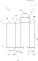
- the following are formed adjacent in sequence: a first side wall, the second outer wall (opposite the first outer wall when the box-like body is mounted), a second side wall (opposite the first side wall when the box-like body is mounted), the first outer wall, a first intermediate tab, the intermediate wall and a second intermediate tab.
- the box-like body can be assembled by fixing the first intermediate tab to the second side wall and the second intermediate tab to the first side wall.
- This construction of the box-like body is particularly simple, efficient and economical.
- the Applicant has observed that the intermediate tabs arranged between the first outer wall and the intermediate wall give a greater strength to the structure of the box-like body, containing an effect of the deformation forces on the same, in particular in the case of deformation forces applied to the first outer wall or the second outer wall opposite the same.
- the slide comprises a base portion to which the casing is constrained.
- the guiding and spacing element comprises a pair of shoulders extending from two opposite flanks of the base portion and normal to the base portion.
- each shoulder has a dimension in the direction normal to the base portion substantially corresponding to a total distance between the first outer wall and the second outer wall, opposite the first outer wall, of the box-like body measured along a direction normal to the first or to the second outer wall.
- the shoulders allow the first outer wall to be kept spaced apart from the product in the casing even in the event of deformations of the first outer wall and, at the same time, allow to guide the extraction and the insertion of the slide from or into the box-like body in an adequate manner.
- the Applicant has determined that the use of the shoulders is particularly advantageous in the case of packagings of limited size, e.g. with a dimension of (at least one) flank equal to or less than 16 mm.
- the slide and the box-like body comprise stop elements suitable for mutually engaging during the extraction movement of the slide from the box-like body, so as to prevent a complete extraction of the slide from the box-like body.
- the stop elements comprise a first stop element made on the second outer wall, near the opening of the box-like body and protruding towards the first outer wall; and a second stop element made on a base portion of the slide to which the casing is constrained, the second stop element protruding from the base portion in the opposite direction with respect to the casing constrained to the base portion.
- first stop element and the second stop element are configured to mutually engage when brought into contact during a movement from the position of complete insertion of the slide inside the box-like body to the position of at least partial extraction of the slide, in so as to prevent a complete extraction of the slide from the box-like body.
- this arrangement of the stop elements is particularly effective and completely prevents the stop element of the box-like element from coming into contact with the product in the casing, in addition to completely concealing the stop elements from view, thereby achieving a more aesthetically pleasing effect.
- the box-like body and the slide are formed by punching a respective sheet of pliable material selected from:
- the construction of the box-like body and the slide in a material derived from cellulose, such as paper, paperboard and cardboard, makes it possible to create a completely biodegradable product with obvious advantages in terms of environmental sustainability.
- a variant of the present invention is directed to a packaging for a product, for example a cosmetic or food product in powder, paste, or granular form, comprising:
- the slide is housed in a sliding manner inside the box-like body between a position of complete insertion of the slide inside the box-like body and a position of at least partial extraction of the slide from the box-like body.
- the slide and the box-like body comprise stop elements suitable for mutually engaging during the extraction movement of the slide from the box-like body, so as to prevent a complete extraction of the slide from the box-like body.
- the casing is made of a material chosen by the group consisting of:
- a variant of the present invention is directed to a packaging for a product, for example a cosmetic or food product in powder, paste, or granular form, comprising:
- the slide is housed in a sliding manner inside the box-like body between a position of complete insertion of the slide inside the box-like body and a position of at least partial extraction of the slide from the box-like body.
- the slide slides on the second outer wall, opposite the first outer wall, and through an opening in the box-like body.
- the slide and the box-like body comprise stop elements suitable for mutually engaging during the extraction movement of the slide from the box-like body, so as to prevent a complete extraction of the slide from the box-like body.
- the stop elements comprise a first stop element made on the second external wall, near the opening of the box-like body and protruding towards the first outer wall; and a second stop element made on a base portion of the slide to which the casing is constrained, the second stop element protruding from the base portion in the opposite direction with respect to the casing constrained to the base portion.
- first stop element and the second stop element are configured to mutually engage when brought into contact during a movement from the position of complete insertion of the slide inside the box-like body to the position of at least partial extraction of the slide, in so as to prevent a complete extraction of the slide from the box-like body.
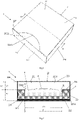
- a packaging 1 according to a first embodiment of the present invention comprises an outer cover 2 and a casing 3.
- the casing 3 is a casing for a cosmetic product 4, preferably in powder or paste form.
- the casing 3 comprises a tank 31 in which the cosmetic product 4 is arranged.
- the cosmetic product 4 is accessible by a user through an access opening 32 to access the tank 31.
- a portion 41 of the cosmetic product 4 protrudes beyond the opening 32 of the casing 3, for example forming a dome.
- the casing 3 has a prismatic structure, in particular a parallelepiped, with two opposite main faces separated by a thickness with a dimension smaller than the dimensions of the main faces.
- the tank 31 is substantially defined by a hollow which extends from a first main face 33 towards a second main face 34 opposite to the first main face 33.
- the access opening 32 to access the tank 31 for the cosmetic product 4 is formed at the first main face 33 of the casing 3.
- the second main face 34 of the casing 3 is used to couple the casing 3 to a slide 21 of the outer cover 2.
- the casing 3 is made of a material suitable for containing the cosmetic product 4 and storing it without altering its characteristics and/or dispersing it.
- the casing is made of a material selected from:
- the outer cover 2 comprises a hollow box-like body 22 and the slide 21, already mentioned.
- the box-like body 22 defines a cavity 221 suitable to completely contain the casing 3 coupled to the slide 21.
- the box-like body 22 comprises a first main wall, or upper wall 223, a second main wall, or bottom wall 222, and three side walls 224, 225 and 226 separating the two main walls 222 and 223.
- the box-like body 22 has a prismatic structure, in particular a parallelepiped structure, with the walls 222, 223 224 and 225 delimiting an opening 227 opposite the remaining wall 226, to access the cavity 221.
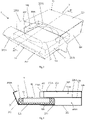
- a guiding and spacing element configured to guide the sliding of the slide 21 inside the box-like body 22 and keep the opening 32 of the casing 3 spaced apart from the upper wall 223 of the box-like body 22, facing the opening 32 of the casing 3.
- the guiding and spacing element defines an air chamber 221B positioned between the opening 32 of the casing 3 and the upper wall 223 of the box-like body 22.
- the guiding and spacing element consists of an intermediate wall 228 provided inside the box-like body 22.
- the intermediate wall 228 is substantially parallel to and spaced apart from the bottom wall 222 and from the upper wall 223 and with the same dimensions.
- the intermediate wall 228 subdivides the box-like body 22, in particular the cavity 221, into two chambers: a first chamber 221A, comprised between the bottom wall 222 and the intermediate wall 228, and a second chamber 221B, comprised between the intermediate wall 228 and the upper wall 223, the second chamber 221B being the air chamber described above.
- the intermediate wall 228 is spaced apart from the upper wall 223 by a distance h1 equal to at least 5 mm, preferably equal to at least 7 mm, more preferably equal to at least 10 mm, measured along a direction normal to both walls 222 and 223, wherein the distance h1 corresponds to the thickness of the second chamber 221B.
- the first chamber 221A is sized to house the casing 3 coupled to the slide 21, preferably in a manner tailored on the dimension.
- a distance h2 between the bottom wall 222 and the intermediate wall 228 substantially corresponds to the dimension of the casing 3 along the direction normal to the upper 223 and bottom 222 walls.
- the intermediate wall 228 is shaped to define a recess 228U, which is U-shaped in plan.
- the recess 228U extends from the access opening 227 to access the box-like body 22 towards the wall 226 opposite the access opening 227.
- the recess 228U has a dimension wx in the direction normal to the side walls 224 and 225, which are opposite to each other, substantially corresponding to a dimension d in the same direction as the access opening 32 to access the tank 31 of the casing - for example, the diameter in the case of a circular opening 32.
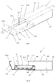
- the box-like body 22 comprises a first stop element 229 - for example, a folded tab - which protrudes from the bottom wall 222 at the access opening 227 to access the box-like body 22 as can be better appreciated in the side sectional view of Figure 4 .
- the slide 21 comprises a base portion 211, a closing portion 212 and a second stop element 213.
- the base portion 211 has a plate-like structure, which has a surface greater than or equal to the surface of the second main face 34 of the casing 3.
- the surface of the second main face 34 of the casing 3 is glued to the base portion 211 of the slide 21.
- the base portion 211 of the slide 21 and, possibly, the second main face 34 of the casing have plan dimensions substantially corresponding to the bottom wall 221 of the box-like body 22.
- the closing portion 212 protrudes from an edge of the base portion 211 and is shaped to completely close the access opening 227 to access the box-like body 22, when the slide 21 is completely inserted into the box-like body 22.
- the closing portion 212 comprises a tab 212A which can be inserted into the cavity 221 of the box-like body 22 at the upper wall 223.
- the tab 212A is sized and shaped to engage with corresponding fixing tabs 224A and 225A protruding from the two side walls 224 and 225 that are opposite each other, respectively, in a manner known and not described herein for brevity's sake.
- the upper wall 223 comprises a recess 223A near the access opening 227 in order to facilitate an engagement/disengagement of the tab 212A to/from the side walls 224 and 225.
- the second stop element 213 protrudes at an edge of the base portion 211 opposite the edge thereof from which the closing portion 212 protrudes.
- the second stop element 213 - for example, a folded tab - protrudes from a surface of the base portion 212 opposite the surface to which the casing 3 is coupled, as described above and as can be better appreciated in the side sectional view of Figure 4 .
- the packaging 1 securely houses the product 4, e.g. a cosmetic product, when in a closed configuration, while allowing an easy and effective use of the cosmetic product 4 when in an open configuration.
- the slide 21 in the closed configuration the slide 21 is completely inserted in the box-like body 22, in particular in the first chamber 221A of the cavity 221, substantially with the second stop element 213 adjacent to the side wall 226 of the box-like body 22 and the closing portion 212 closing the access opening 227 to access the box-like body 22.
- the dome 41 of the cosmetic product 4 protruding from the opening 32 of the casing 3 passes through the recess 228U of the intermediate wall 228, advantageously without coming into contact with it.
- the intermediate wall 228 blocks casing 3 in place in the first chamber.
- the intermediate wall 228 keeps the opening 32 of the casing 3 and, therefore, the cosmetic product 4 substantially at the distance hx from the upper wall 223.
- the slide 21 In the open position, the slide 21 is extracted from the box-like body 22 and the second stop element 213 of the slide 21 engages with the first stop element of the box-like body 229. Consequently, the casing 3 is arranged at least partially outside the box-like body 22, preferably so that the entire opening 32 of the casing is exposed to the environment outside the box-like body 22, so as to allow a practical collection of a quantity of product 4 by means of a finger or a tool - for example, a brush or a sponge.
- the slide 21 slides between the position of complete insertion of the slide 21 inside the box-like body 22 and the position of at least partial extraction of the slide 21 from the box-like body 22 just described, with the intermediate wall 228 acting as a sliding guide for the slide 21 and the casing 3 coupled thereto, so as to allow a substantially linear insertion/extraction movement while preventing the slide 21 from getting stuck or the cosmetic product 4 from coming into contact with the box-like body 22 due to deviations from a linear path.
- the dimension lx of the recess 228U along a movement direction lm of the slide 21 is such as to ensure that the opening 32, and thus the dome 41 of cosmetic product 4, comes into contact with the intermediate wall 228 during the extraction/insertion movement.
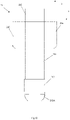
- both the box-like body 22 and the slide 21 are obtained by punching and folding a single sheet, or other plate-like element.
- the box-like body 22 is made in a simple way and with a minimum amount of material.
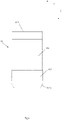
- the box-like body 22 is made with a first side wall 224 adjacent - along a direction X shown in Figure 5 - to the bottom wall 222, a second side wall 225 adjacent to both the bottom side wall 222 and the upper wall 223, a first intermediate tab 228A adjacent to the upper wall 223 (in a manner analogous to a classical box with a parallelepiped structure) and the intermediate wall 228 adjacent to both the first intermediate tab 228A and a second intermediate tab 228B.
- the side wall 226 is adjacent to the upper wall 223 - along a direction Y normal to the direction X - and the first fixing tabs 224A, 225A as well as the second fixing tabs 224B and 225B are adjacent to opposite edges of the side walls 224 and 225, respectively.
- the box-like body 22 by simply closing the walls 222 - 225 on themselves, with the first intermediate tab 228A being fixed - for example, glued or welded - to the second side wall 225 and the second intermediate tab 228B being fixed - for example, glued or welded - to the first side wall 224 opposite the second side wall 225.
- the dimensions of the intermediate tabs 228A and 228B allow the distance h1 of the intermediate wall 228 from the upper wall 223 and the distance h2 of the intermediate wall 228 from the bottom wall 222 to be simply and precisely defined.
- the box-like body 22 and the slide 21 are made of a pliable material selected from:
- FIG. 7 - 10 a packaging 6 is described according to a different embodiment.
- components similar to what has been described above are indicated by the same references and their description is not repeated here for the sake of brevity.
- the guiding and spacing element comprises a pair of spacing shoulders 215 and 216 provided on the slide 21.
- the spacing shoulders 215 and 216 are formed at opposite flanks of the base portion 211 of the slide 21, transverse to the flanks from which the closing portion 212 and the second stop element 213 protrude.
- the spacing shoulders 215 and 216 extend in a direction normal to the major surfaces of the base portion with an extension h3 along the direction normal to the bottom wall 222 and to the upper wall 223 of the box-like body 22 substantially equal to the total distance ht between the two walls 222 and 223.
- spacing shoulders 215 and 216 are formed at the end of the base portion 211 from which the second stop element 213 protrudes and extend towards the opposite end of the base portion 211 by a dimension equal to at least 33% of the length of the base portion 211.
- one free end of the spacing shoulders 215 and 216 is in contact with the upper wall 223 of the box-like body 22. This gives a greater strength to the slide 21 and the box-like body 22 together, when the slide 21 is completely inserted into the box-like body 22 - and the casing 3 is completely housed in the cavity 221, in particular with respect to forces applied on the bottom wall 222 and/or on the upper wall 223 along the direction normal to said walls.
- the spacing shoulders 215 and 216 keep the casing 3, in particular the opening 32 - and, also, the cosmetic product 4 - at a distance h3 from the upper wall 223 of the box-like body 22 along the direction normal to the bottom wall 222 and to the upper wall 223.
- the air chamber described above and having a thickness corresponding to the distance h3 is therefore created between the casing 3, in particular the opening 32, and the upper wall of the box-like body 22.
- the distance h3 is equal to at least 5 mm, preferably equal to at least 7 mm, more preferably equal to at least 10 mm.
- the spacing shoulders 215 and 216 guide the slide 21 during its movement of extraction/insertion from/into the box-like body 22.
- the spacing shoulders 215 and 216 during the extraction/insertion movement, slide in the cavity 221 of the box body 22 substantially in contact with the side walls 224 and 225, respectively, and the upper wall 223. In this way, a substantially linear insertion/extraction movement is achieved, preventing the slide 21 from getting stuck or the cosmetic product 4 from coming into contact with the box-like body 22 due to deviations from a linear path.
- both the box-like body 22 and the slide 21 of the outer cover 2 of the packaging 6 are obtained by punching and folding a single sheet, or other plate-like element.
- the casing can be hollow instead of solid in order to make it lighter.
- the intermediate wall is solid, i.e. without the U-shaped recess, so that the two chambers of the cavity are completely isolated.
- the outer cover and in particular the box-like body may have a shape other than parallelepiped.
- the box-like body is made with a prism structure with a base other than square or rectangular, for example hexagonal.
- a non-prismatic structure such as pyramidal, truncated-pyramidal, conical, truncated-conical, etc.
Landscapes
- Engineering & Computer Science (AREA)
- Mechanical Engineering (AREA)
- Packages (AREA)
Applications Claiming Priority (1)
| Application Number | Priority Date | Filing Date | Title |
|---|---|---|---|
| IT102020000027492A IT202000027492A1 (it) | 2020-11-17 | 2020-11-17 | Confezione per prodotto |
Publications (1)
| Publication Number | Publication Date |
|---|---|
| EP4001144A1 true EP4001144A1 (fr) | 2022-05-25 |
Family
ID=74347627
Family Applications (1)
| Application Number | Title | Priority Date | Filing Date |
|---|---|---|---|
| EP21207911.5A Withdrawn EP4001144A1 (fr) | 2020-11-17 | 2021-11-12 | Emballage pour un produit |
Country Status (2)
| Country | Link |
|---|---|
| EP (1) | EP4001144A1 (fr) |
| IT (1) | IT202000027492A1 (fr) |
Citations (2)
| Publication number | Priority date | Publication date | Assignee | Title |
|---|---|---|---|---|
| DE2030830A1 (en) * | 1970-06-23 | 1971-12-30 | Fa. A. Landerer, 7100 Heilbronn | Transparent folding box of pvc with cardboard insert - and end tabs |
| WO2006015117A1 (fr) * | 2004-07-28 | 2006-02-09 | Meadwestvaco Corporation | Appareil et procede de stockage et de protection des dispositifs de distribution de medicaments |
-
2020
- 2020-11-17 IT IT102020000027492A patent/IT202000027492A1/it unknown
-
2021
- 2021-11-12 EP EP21207911.5A patent/EP4001144A1/fr not_active Withdrawn
Patent Citations (2)
| Publication number | Priority date | Publication date | Assignee | Title |
|---|---|---|---|---|
| DE2030830A1 (en) * | 1970-06-23 | 1971-12-30 | Fa. A. Landerer, 7100 Heilbronn | Transparent folding box of pvc with cardboard insert - and end tabs |
| WO2006015117A1 (fr) * | 2004-07-28 | 2006-02-09 | Meadwestvaco Corporation | Appareil et procede de stockage et de protection des dispositifs de distribution de medicaments |
Also Published As
| Publication number | Publication date |
|---|---|
| IT202000027492A1 (it) | 2022-05-17 |
Similar Documents
| Publication | Publication Date | Title |
|---|---|---|
| US20020092787A1 (en) | Plastic shoe box assembly | |
| AU2010212444B2 (en) | Packing box | |
| AU2015100684A6 (en) | Containing Box Structure | |
| RU2506214C2 (ru) | Пачка | |
| EP1725460B1 (fr) | Etui rigide pour articles de tabac | |
| RU2600918C2 (ru) | Емкость с шарнирной крышкой | |
| EP4001144A1 (fr) | Emballage pour un produit | |
| EP1855960B1 (fr) | Paquet de cigarettes composite à couvercle articulé | |
| JP6230869B2 (ja) | 包装箱 | |
| KR101129268B1 (ko) | 가변형 포장용상자 | |
| EP3099585B1 (fr) | Paquet rigide d'articles pour fumeurs dont le volume interne est divisé en deux chambres distinctes | |
| KR20090058071A (ko) | 덮개가 구비된 포장상자 | |
| KR101132651B1 (ko) | 가변형 포장용상자 | |
| KR20120122773A (ko) | 전시용 포장박스 및 이를 이용한 포장방법 | |
| CN116729764B (zh) | 包装盒 | |
| KR200290714Y1 (ko) | 포장 케이스 | |
| KR200407957Y1 (ko) | 포장 상자 | |
| KR200383867Y1 (ko) | 골판지를 이용한 포장용 상자 | |
| KR100957752B1 (ko) | 컬링이 형성된 다면체 포장박스의 제작방법 | |
| KR20080114121A (ko) | 상부개방 포장상자 | |
| JP7235606B2 (ja) | 包装用箱 | |
| JP4167748B2 (ja) | 緩衝固定収納箱 | |
| CN109720743B (zh) | 一种正六棱柱的香烟盒体 | |
| KR200342045Y1 (ko) | 담배갑 | |
| JP3116865U (ja) | 筒状包装容器 |
Legal Events
| Date | Code | Title | Description |
|---|---|---|---|
| PUAI | Public reference made under article 153(3) epc to a published international application that has entered the european phase |
Free format text: ORIGINAL CODE: 0009012 |
|
| STAA | Information on the status of an ep patent application or granted ep patent |
Free format text: STATUS: THE APPLICATION HAS BEEN PUBLISHED |
|
| AK | Designated contracting states |
Kind code of ref document: A1 Designated state(s): AL AT BE BG CH CY CZ DE DK EE ES FI FR GB GR HR HU IE IS IT LI LT LU LV MC MK MT NL NO PL PT RO RS SE SI SK SM TR |
|
| STAA | Information on the status of an ep patent application or granted ep patent |
Free format text: STATUS: THE APPLICATION IS DEEMED TO BE WITHDRAWN |
|
| 18D | Application deemed to be withdrawn |
Effective date: 20221126 |