EP4001148B1 - Récipient et son procédé de fabrication - Google Patents
Récipient et son procédé de fabrication Download PDFInfo
- Publication number
- EP4001148B1 EP4001148B1 EP21208641.7A EP21208641A EP4001148B1 EP 4001148 B1 EP4001148 B1 EP 4001148B1 EP 21208641 A EP21208641 A EP 21208641A EP 4001148 B1 EP4001148 B1 EP 4001148B1
- Authority
- EP
- European Patent Office
- Prior art keywords
- coupling portion
- container
- support
- operating position
- sheet
- Prior art date
- Legal status (The legal status is an assumption and is not a legal conclusion. Google has not performed a legal analysis and makes no representation as to the accuracy of the status listed.)
- Active
Links
Images






Classifications
-
- B—PERFORMING OPERATIONS; TRANSPORTING
- B65—CONVEYING; PACKING; STORING; HANDLING THIN OR FILAMENTARY MATERIAL
- B65D—CONTAINERS FOR STORAGE OR TRANSPORT OF ARTICLES OR MATERIALS, e.g. BAGS, BARRELS, BOTTLES, BOXES, CANS, CARTONS, CRATES, DRUMS, JARS, TANKS, HOPPERS, FORWARDING CONTAINERS; ACCESSORIES, CLOSURES, OR FITTINGS THEREFOR; PACKAGING ELEMENTS; PACKAGES
- B65D5/00—Rigid or semi-rigid containers of polygonal cross-section, e.g. boxes, cartons or trays, formed by folding or erecting one or more blanks made of paper
- B65D5/42—Details of containers or of foldable or erectable container blanks
- B65D5/64—Lids
- B65D5/66—Hinged lids
- B65D5/6602—Hinged lids formed by folding one or more extensions hinged to the upper edge of a tubular container body
- B65D5/6608—Hinged lids formed by folding one or more extensions hinged to the upper edge of a tubular container body the lid being held in closed position by self-locking integral flaps
-
- B—PERFORMING OPERATIONS; TRANSPORTING
- B65—CONVEYING; PACKING; STORING; HANDLING THIN OR FILAMENTARY MATERIAL
- B65D—CONTAINERS FOR STORAGE OR TRANSPORT OF ARTICLES OR MATERIALS, e.g. BAGS, BARRELS, BOTTLES, BOXES, CANS, CARTONS, CRATES, DRUMS, JARS, TANKS, HOPPERS, FORWARDING CONTAINERS; ACCESSORIES, CLOSURES, OR FITTINGS THEREFOR; PACKAGING ELEMENTS; PACKAGES
- B65D5/00—Rigid or semi-rigid containers of polygonal cross-section, e.g. boxes, cartons or trays, formed by folding or erecting one or more blanks made of paper
- B65D5/42—Details of containers or of foldable or erectable container blanks
- B65D5/4295—Ventilating arrangements, e.g. openings, space elements
-
- B—PERFORMING OPERATIONS; TRANSPORTING
- B65—CONVEYING; PACKING; STORING; HANDLING THIN OR FILAMENTARY MATERIAL
- B65D—CONTAINERS FOR STORAGE OR TRANSPORT OF ARTICLES OR MATERIALS, e.g. BAGS, BARRELS, BOTTLES, BOXES, CANS, CARTONS, CRATES, DRUMS, JARS, TANKS, HOPPERS, FORWARDING CONTAINERS; ACCESSORIES, CLOSURES, OR FITTINGS THEREFOR; PACKAGING ELEMENTS; PACKAGES
- B65D5/00—Rigid or semi-rigid containers of polygonal cross-section, e.g. boxes, cartons or trays, formed by folding or erecting one or more blanks made of paper
- B65D5/20—Rigid or semi-rigid containers of polygonal cross-section, e.g. boxes, cartons or trays, formed by folding or erecting one or more blanks made of paper by folding-up portions connected to a central panel from all sides to form a container body, e.g. of tray-like form
- B65D5/2052—Rigid or semi-rigid containers of polygonal cross-section, e.g. boxes, cartons or trays, formed by folding or erecting one or more blanks made of paper by folding-up portions connected to a central panel from all sides to form a container body, e.g. of tray-like form characterised by integral closure-flaps
- B65D5/2057—Inter-engaging self-locking flaps
-
- B—PERFORMING OPERATIONS; TRANSPORTING
- B65—CONVEYING; PACKING; STORING; HANDLING THIN OR FILAMENTARY MATERIAL
- B65D—CONTAINERS FOR STORAGE OR TRANSPORT OF ARTICLES OR MATERIALS, e.g. BAGS, BARRELS, BOTTLES, BOXES, CANS, CARTONS, CRATES, DRUMS, JARS, TANKS, HOPPERS, FORWARDING CONTAINERS; ACCESSORIES, CLOSURES, OR FITTINGS THEREFOR; PACKAGING ELEMENTS; PACKAGES
- B65D2401/00—Tamper-indicating means
- B65D2401/60—Tearable part both of the container and of the closure
-
- B—PERFORMING OPERATIONS; TRANSPORTING
- B65—CONVEYING; PACKING; STORING; HANDLING THIN OR FILAMENTARY MATERIAL
- B65D—CONTAINERS FOR STORAGE OR TRANSPORT OF ARTICLES OR MATERIALS, e.g. BAGS, BARRELS, BOTTLES, BOXES, CANS, CARTONS, CRATES, DRUMS, JARS, TANKS, HOPPERS, FORWARDING CONTAINERS; ACCESSORIES, CLOSURES, OR FITTINGS THEREFOR; PACKAGING ELEMENTS; PACKAGES
- B65D2585/00—Containers, packaging elements or packages specially adapted for particular articles or materials
- B65D2585/30—Containers, packaging elements or packages specially adapted for particular articles or materials for articles particularly sensitive to damage by shock or pressure
- B65D2585/36—Containers, packaging elements or packages specially adapted for particular articles or materials for articles particularly sensitive to damage by shock or pressure for biscuits or other bakery products
- B65D2585/363—Containers, packaging elements or packages specially adapted for particular articles or materials for articles particularly sensitive to damage by shock or pressure for biscuits or other bakery products specific products
- B65D2585/366—Pizza
Definitions
- the object of the present invention is a container for housing products, for example of food type.
- the container, object of the present invention can be of the type to give evidence of tampering and be applied in the field of packaging food products, e.g. for pizzas, in order to ensure the supply of intact products, which are not all altered.
- the object of the present invention is also a process for attaining said container as well as a method for closing the same.
- the containers today attained with tampering-evidence mechanisms are mainly used in the pharmaceutical sector in order to indicate the danger of a possible tampering or substitution of the product, hence ensuring product integrity for the consumer. Nevertheless it is indicated that such containers have a structurally complex closure mechanism, hard to reinforce in brief time periods.
- tamper-evident container comprises a store reclosable following the engagement between a first coupling portion carried by a closure system and a second coupling portion carried by the store itself.
- the first coupling portion has two foldable tabs configured for being engaged within a second coupling portion, while the latter is defined by a "V" folded tongue having a pocket adapted to receive the first coupling portion.
- the tabs are then configured for being inserted in the pocket and constrained to the second coupling portion: following a first open condition of the container, the tabs are configured for being detached from the closure system.
- Such container has important limitations. In fact it should be observed that such container does not allow giving clear evidence of tampering in the case that the container has been previously opened. In fact, the user perceives the integrity of the container only based on the perception of the resistance exerted by the first coupling portion on the second coupling portion, without having visual evidence of tampering. Furthermore, such container attains a complex engagement between the first and second coupling portions, which cannot be executed in an automated manner, nor in a quick manner by an operator.
- a second example of a tamper-evident container is described in the patent application No. US 2011/180537 A1 .
- Such container comprises a store reclosable following the engagement between a first coupling portion carried by a closure system and a second coupling portion carried by the store.
- the first coupling portion comprises a tongue engaged with the closure system by means of a weakening portion and configured for being engaged within a single opening made on a panel carried by the store.
- the opening of the second coupling portion is entirely counter-shaped with respect to the first coupling portion and is configured for being aligned with the latter, in a manner such to allow the insertion thereof and define a closed condition of the container.
- the first coupling portion is thus configured for being separated from the closure system, giving evidence of a first opening of the container.
- the Applicant has detected that the container described in the United States patent application No. US 2011/180537 A does not allow defining an effective closure, capable of giving correct evidence of tampering of the container. Indeed, the Applicant has detected that the first coupling portion is easily extractable from the opening made on the panel engaged with the store without said first coupling portion being separated from the closure system.
- Object of the present invention is therefore that of substantially resolving at least one of the drawbacks and/or limitations of the preceding solutions.
- a first objective of the present invention is to provide a container which can effectively give evidence of tampering following a first opening attempt of the same.
- a further object of the present invention is that of providing a tamper-evident container that can be easily reinforced, both in an automated manner and by an authorized operator.
- Another object of the present invention is to provide a container that is simple and quick to manufacture, which allows minimizing the consumption of material and consequently the costs of production and transport.
- a further object of the present invention is to provide a container that is flexible in use which can be effectively employed on different types of containers of sheet material.
- Another object of the present invention is to provide a container capable of preventing the contact between one or more products housed in the container itself in the event in which the latter is closed by a user.
- the product it is intended an article or a composite of articles of any kind.
- the product can be of food type and be in the solid state, liquid state or in gel form, i.e. in the form of two or more of the aforesaid aggregation states.
- the product can comprise: pizza, pasta, meat, fish, cheese, treated meats, ready and frozen meals of various kind.
- paper material it is intended paper or cardboard, for example having at least 50% by weight, optionally at least 70% by weight, of organic material comprising one or more of cellulose, hemicellulose, lignin, lignin derivatives.
- the paper sheet material can be covered at least partly by means of a coating made of plastic material, e.g. a film, whose object is that of: reinforcing the paper sheet material, defining a water and/or moisture barrier.
- the coating can have a thickness variable between 10 and 50 ⁇ m and can be made with one or more of the following materials: LDPE, HDPE, PP, PE.
- blade it is intended a flat semifinished product made of sheet material, for example paper, foldable on itself in order to make a container.
- the blank can be made of a single piece and obtainable by means of die cutting a single sheet.
- sheet material it is intended a material that has two dimensions, for example the length and the width, considerably larger than a third dimension, such as the thickness.
- the support 2 can comprise at least one base 2a and at least one lateral wall 4 emerging from an external perimeter of the base 2a; the at least one lateral wall delimits, opposite the base 2a, a free edge from which at least one abutment flap 2c can emerge: the abutment flap 2c is arranged facing the base 2a and is substantially extended parallel to the base 2a so as to define a kind of internal flange of the support 2.
- the flap it is intended a band of material, for example made of sheet material, having a lengthwise extension along a longitudinal direction greater than a width-wise transverse extension.
- the flap can comprise a tongue of sheet material paper whose length is at least twice the extension width-wise and in which the length and the width are considerably greater than a third dimension defined by the thickness.
- Reference number 1 overall indicates a container for housing products, for example of food type.
- the container 1 comprises at least one support 2 of sheet material, defining an internal volume 3, configured for housing products, e.g. pizzas, sandwiches or wraps.
- the support 2 has at least one base 2a with rectangular shape adapted to receive the product, starting from which at least one lateral wall 4 emerges which defines a free edge 6 and, together with the base 2a, delimits the internal volume 3.
- the lateral wall 4 perimetrically delimits the base 2a of the support 2 and is configured for emerging from the latter in a manner such to define a three-dimensional shape of the same support 2.
- the support 2 which has a quadrangular prismatic shape (lateral walls 4 that are for example flat and having rectangular shape).
- lateral walls 4 that are for example flat and having rectangular shape.
- the lateral wall 4 has a lower height than a longitudinal extension of the same lateral wall.
- the lateral wall 4 defines a lateral portion of reduced height to substantially define a tray, configured for housing products having a limited height.
- the support 2 has a first and a second lateral wall 4a, 4b that are adjacent to each other and configured for being engaged in a manner such to maintain the support 2 in a stable three-dimensional configuration.
- the first lateral wall 4a is extended along a predetermined extension direction between two longitudinal ends which, following the formation of the support 2, define respective corner portions.
- the second lateral wall 4b is also extended along a predetermined extension direction transversely, optionally orthogonally, with respect to the first lateral wall 4a, between respective longitudinal ends: the first and the second lateral wall 4a, 4b are therefore adjacent to each other at the respective end portions.
- the first and the second lateral wall 4a, 4b following the attainment of the stable three-dimensional configuration, are then engaged with each other to define an external edge of the support 2.
- the first lateral wall can comprise at least one air-vent opening 17 defined at at least one longitudinal end of same first lateral wall 4a, configured for allowing the communication between the internal volume 3 of the support 2 and the external environment.
- the air-vent opening 17 then allows expelling the air and/or the vapor present in the internal volume 3, in a manner such to maintain a constant humidity level within the container itself and consequently preserving the consistency and the taste of the food product.
- the air-vent opening 17 is delimited by an undercut portion configured for being constrained with a locking tongue 70 carried by a junction portion 18, in order to define the stable three-dimensional configuration of the support.
- the first lateral wall 4a can have at least two air-vent openings 17 respectively arranged at opposite longitudinal ends of the first lateral wall 4a. Each air-vent opening 17 is thus engageable with a respective locking tongue 70 carried by the second lateral wall 4b.
- the junction portion 18 comprises a superimposition tongue on which - for example following the attainment of a notch of the same superimposition tongue - a through opening is defined that is delimited by a perimeter edge of substantially circular shape; the locking tongue 70 is defined on the superimposition tongue and is configured to be constrained to the air passage opening 17.
- the locking tongue 70 is integrally joined to a section of the perimeter edge of the through opening and is movable via rotation with respect to the same edge between a position in which it faces the air-vent opening 17 (in such position the tongue 70 substantially lies parallel to the first lateral wall 4a), and a folded position in which the locking tongue 70 is constrained within the air-vent opening 17 in order to engage the first and the second lateral wall 4a, 4b.
- the locking tongue 70 in the folded position ( figure 2 ), is configured for maintaining the lateral walls of the support in a three-dimensional configuration.
- the support 2 can have a third lateral wall 4c emerging from the base 2a starting from an external perimeter edge of the base 2a.
- the first, the second and the third lateral wall 4a, 4b, 4c emerge from the base 2a of the support along a same direction, in a manner such to delimit the internal volume 3.
- the first, the second and the third lateral wall 4a, 4b and 4c are then adjacent to each other, defining height-wise the triangular prismatic structure of the container.
- the third lateral wall 4c can stably carry the locking tongue 70 configured for being engaged with a respective air passage opening 17 defined on the first lateral wall 4a.
- the support 2 can further comprise a fourth lateral wall 4d emerging from the external perimeter edge of the base 2a: the first, the second, the third and the fourth lateral wall (4a, 4b, 4c, 4d) delimit height-wise the quadrangular prismatic structure of the support 2.
- the first and the third lateral wall 4a, 4c are opposite each other with respect to the base 2a of the support; in the same manner, the second and the fourth lateral wall 4b, 4d face each other and are opposite with respect to the base 2a of the support.
- first and the third wall 4a, 4c respectively define a front wall and a rear wall of the support, joined together by means of the second and of the fourth wall 4b, 4d which define respective lateral walls of the support.
- the ends of the first, second, third and fourth lateral walls 4a, 4b, 4c, 4d thus delimit the free edge 6.
- the support 2 comprises an abutment flap 2c emerging from at least one section of the free edge 6 so as to at least partly face the base 2a.
- the abutment flap 2c can be folded with respect to the section of free edge 6 with which it is engaged in order to define, in cooperation with the free edge 6 (and/or with an intermediate flap 26 described hereinbelow), a passage opening 5 configured for placing the internal volume 3 in communication with the external environment. It should be observed that the abutment flap 2c can emerge starting from at least one section of the free edge 6 defined by at least one between the first, the second, the third and the fourth lateral walls 4a, 4b, 4c and 4d. However, it is possible that the abutment flap 2c can emerge starting from a section of the free edge 6 defined by one or more lateral walls 4.
- the support 2 can comprise an abutment flap 2c emerging from the free edge section 6 defined at the first wall 4a and facing the third wall 4c.
- the support 2 can comprise a first abutment flap emerging from the second wall 4c and a second abutment flap emerging from the fourth wall 4d: the first and the second abutment flap are directed towards each other.
- a plurality of abutment flaps 2c each of which emerging from a respective lateral wall 4.
- each abutment flap 2c is extended for the entire longitudinal extension of the lateral wall 4 with which it is engaged. In other words, each abutment flap 2c is extended for the entire section of the free edge 6 defined by the lateral wall with which said flap 2c is directly carried.
- the abutment flap 2c has a limited extension along a direction facing the internal volume 3 of the support 2, in a manner such to obstruct the access to the internal volume 3 to a limited extent and consequently maximize the extension of the through opening 5: the abutment flap 2c then allows an easy insertion of the food product in the internal volume 3.
- the extension of the abutment flap 2c along a direction entering the internal volume 3 can be comprised between 2 cm and 10 cm, while the ratio between the extension of the abutment flap 2c along the direction entering the internal volume 3 and the extension of the lateral wall with which it is engaged can be comprised between 0.06 and 0.3.
- the support 2 can also comprise a separator 14 extended in the internal volume 3 interposed between the abutment flap 2c and the base 2a of the same support 2, configured for dividing a central zone of the support adapted to receive the product, from a peripheral zone of the support at which the abutment flap 2c is defined.
- the separator 14 is integrally joined to the abutment flap 2c and folded relative to the latter along an end edge 6a opposite the free edge 6.
- the separator 14 can be engaged with the base 2a via mechanical interference or via gluing.
- the separator 14 is extended width-wise between the end edge 6a and the base 2a.
- the separator 14 can be extended transversely, optionally orthogonally, to the abutment flap 2a with which it is engaged, thus having equal height with respect to each lateral wall 4. As shown in the enclosed figures, the separator 14 is extended lengthwise substantially for the entire extension of the abutment flap 2c, substantially defining a channel delimited by the support 14, by the abutment flap 2c and by the lateral wall 4 with which the latter is integrally joined.
- the separator 14 is also configured for dividing the internal volume 3 in a first sub-chamber 40 configured for receiving the product and in a second sub-chamber 45 delimited by the channel and arranged at a perimeter zone of the support 2.
- the channel faces the air-vent opening 17, in a manner such to allow the air and/or vapor present within the second sub-chamber 45 to be expelled from the support through the air-vent opening 17.
- the separator 14 can then be interposed between the lateral wall 4 of the support on which the air-vent opening 17 is defined and the central zone of the support adapted to receive the product.
- the separator 14 can comprise at least one through access 16 configured for placing in fluid communication the first and the second sub-chamber 40, 45: by means of the through access 16, the air and/or the vapor present within the first sub-chamber 40 are conveyed within the second sub-chamber 45 and expelled through the air-vent opening 17.
- the through access 16 can have a circular or polygonal conformation, with dimensions comprised between 20% and 90% of the width of the same separator 14, in a manner such to allow an effective transfer of fluid between the first and the second sub-chambers 40, 45 without compromising the structural strength of the separator 14.
- Each through access 16 is offset with respect to an air access opening 17, in a manner such to prevent a user from inserting a finger and/or a tool through the through access 16 and the air access opening 17 to contaminate the product placed in the central zone of the support.
- the separator 14 can further comprise a plurality of through accesses 16 that are equidistant from each and distributed for the entire length of the same separator 14, configured for maximizing the transfer of fluid between the first and the second sub-chamber 40, 45.
- the support 2 can comprise a single separator 14 integrally joined to the first lateral wall 4a; alternatively, the support 2 can comprise a plurality of separators 14, respectively integrally joined to the first and to the second abutment flap 2c.
- the support 2 can further comprise at least one intermediate flap 26 emerging from at least one section of the free edge 6 of the support 2 adjacent to the support flap 2c.
- the intermediate flap 26 faces the base 2a of the support, in a manner such to define a portion folded along the section of free edge 6 with which it is engaged and perimetrically delimiting the through opening 5.
- the intermediate flap 26 has a rectangular shape extended for the entire the free end section defined by the lateral wall with which it is engaged.
- the intermediate flap 26 has a limited extension along a direction facing the internal volume 3 of the support 2, in a manner such to maximize the extension of the through opening 5 and allow an easy insertion of the food product in the internal volume 3.
- the extension of the intermediate flap 26 along a direction entering the internal volume 3 can be comprised between 2 cm and 10 cm.
- the ratio between the extension of the intermediate flap 26 along the direction entering the internal volume 3 and the extension of the lateral wall with which it is engaged can be comprised between 0.06 and 0.3.
- the intermediate flap 26 is substantially identical to the abutment flap 2c. As is visible in the enclosed figures, the intermediate flap 26 is defined adjacent to the abutment flap 2c, being superimposed on the abutment flap 2c at a longitudinal end of the latter.
- the intermediate flap 26, in the closed condition of the container 1, can be then interposed between the same abutment flap 2c and the closure system 7.
- the intermediate flap 26 can further have a through opening 28 with closed profile, arranged, at least in the closed condition of the closure system 7, facing the abutment flap 2c.
- the through opening 28 can be defined at a longitudinal end of the intermediate flap 26 superimposed on the abutment flap 2c.
- the through opening 28 is configured for allowing a first coupling portion 12 carried by the closure system to reach a second coupling portion 13 defined at the longitudinal end of the abutment flap 2c arranged within the intermediate flap 26.
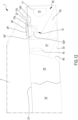
- the intermediate flap 26 can comprise a first and the second intermediate flap 26', 26" ( figure 2 , 11 and 12 ) emerging respectively from sections of the free edge 6 defined by the second and by the fourth lateral wall 4b, 4d; first and second intermediate flaps 26', 26" are both superimposed on an abutment flap 2c defined at the first wall 4a.
- the support 2 can comprise a single intermediate flap 26 integrally joined to the first wall 4a, which is superimposed on respective terminal portions of the abutment flaps 2c carried by the second and by the fourth lateral wall 4b, 4d.
- the support 2 can further comprise a slit 27 made following the definition of a notch on the same intermediate flap 26 and/or on the abutment flap 2c, configured for allowing the insertion of at least one connection tongue 25 within the internal volume 3 of the support 2.
- the slit 27 is defined in proximity to the free edge 6 and is extended parallel to the latter for a size comprised between 5% and 80% of the longitudinal extension from terminal portions of the lateral wall which defines the same free edge 6.
- the slit 27 is extended for most of the longitudinal extension of the intermediate flap 26 on which it is defined.
- the slit 27 is extended for a limited section of the intermediate edge 27 comprised between 10% and 40% of the longitudinal extension of the intermediate flap 26.
- the support 2 is made of sheet material and obtained for example via folding.
- the support 2 is made of sheet material paper (paper or cardboard); in particular, the sheet material used has a basis weight comprised between 100 and 500 g/m 2 , in particular comprised between 200 and 400 g/m 2 .
- the container 1 comprises a closure system 7, also of sheet material, engaged at at least one section of the free edge 6 and movable, in particular via rotation, with respect to the support 2.
- the closure system 7 is configured for defining at least one closed condition in which the same closure system 7 prevents the communication between the internal volume 3 of the support 2 and the external environment and an open condition in which it allows a user to access the internal volume 3 of the support 2 (see for example figures 2 , 9 , 10 and 12 ).
- the system 7 substantially represents a cover adapted to cooperate with the support 2 so as to manage the access to the internal volume 3.
- the closure system 7 is, in a non-limiting manner, integrally joined at the free end section 6 defined by the third wall 4c, being movable via rotation around the latter at least between the open and closed conditions.
- a closure system 7 that is separate and completely separable from the free edge 6, in fact defining a cover removably engageable with the support 2.
- the closure system 7 comprises at least one closure panel 8 of sheet material and engaged with at least one section of the free edge 6.
- the closure panel 8 has a conformation that is counter-shaped with respect to the free edge 6 in a manner such to allow, in the closed condition of the closure system 7, to entirely obstruct the passage opening 5 and prevent the access to the internal volume 3.
- the closure panel 8 in the closed condition of the closure system 7, is at least partly in contact with the abutment flap 2c and with the intermediate flap 26.
- the closure panel 8 can also have at least one connection tongue 25 configured for being inserted, in the closed condition of the system 7, within the volume 3 of the support 2.
- the connection tongue 25 is integrally joined to the closure panel 8 and emerges from the latter starting from an external perimeter edge 8a delimiting the closure panel 8.
- the connection tongue 25 substantially represents an extension of the closure panel 8 adapted to be inserted, in the closed condition of the system 7, within the slit 27 of each intermediate flap 26.
- the connection tongue 25 is defined from a flat body of sheet material having, as a non-limiting example, rectangular shape. In the closed condition of the closure system 7, the connection tongue 25 directly faces, in particular contacts, a part of a lateral wall 4 of the support 2, extended parallel to the latter.
- connection tongue 25 is also movable via rotation with respect to the closure panel 8 around a section of the external perimeter edge 8a.
- the connection tongue 25, in the closed condition of the closure system 7, is configured for defining, according to a transverse section and in cooperation with the closure panel 8, a substantially "L" shape: in such condition the connection tongue 25 is substantially extended parallel to a lateral wall 4 of the support 2.
- the closure panel 8 can have three connection portions 25, each of which, in the closed condition of the closure system 7, is respectively insertingly within a slit 27 defined on the first and on the second intermediate flap 26', 26" and on the abutment flap 2c.
- the closure panel 8 can have a single connection portion 25 insertable within a respective slit 27 defined on the intermediate flap 26 integrally joined to the first lateral wall 4a.
- the closure system 7 is at least partly made, in particular entirely, of sheet material paper (paper, cardboard or corrugated cardboard); the sheet material used has a basis weight comprised between 100 and 500 g/m 2 .
- the sheet material paper used for attaining the closure system 7 is equivalent to the sheet material used for attaining the support 2, in particular they are both obtained starting from only a single sheet of paper material.
- the container 1 comprises at least one first coupling portion 12, carried by the closure system 7, and at least one second coupling portion 13 defined on at least one abutment flap 2c.
- the first coupling portion 12 is configured for being stably engaged with an undercut portion 13b of the second coupling portion 13 in a manner such to define a locking condition.
- the first coupling portion 12 is engageable with the second coupling portion 13 following the arrangement of the closure system 7 in contact with the abutment flap 2c and with the intermediate flap 26, in a manner such to arrange the same first coupling portion 12 in superimposition on the second coupling portion 13 and on the display opening 28.
- the attainment of the engagement between the first and second coupling portions 12, 13 is only reached following the alignment of the latter along a direction orthogonal to the base 2a of the support 2.
- the first coupling portion 12 is attained on the closure system 7 following the definition on the latter of a notch adapted to define a through seat 7a delimited by a perimeter edge with closed profile which is arranged within the external perimeter edge 8a of the closure portion. Consequently, the first coupling portion 12 is defined arranged within the through seat 7a and within the external perimeter edge 8a. However, it is possible to attain a first coupling portion 12 emerging starting from the external perimeter edge 8a of the closure portion 8.
- the first coupling portion 12 comprises a central body 12a and a base body 12c integrally joined to the central body by means of a folding edge 22: the central body 12a is movable with respect to the base body 12c around the folding edge 22.
- the central body 12a and in general the first coupling portion 12, can thus be movable around the folding edge 22 at least between a first and a second operating position.
- the first coupling portion 12 In the first operating position, the first coupling portion 12 is disengaged from the second coupling portion 13, at least partly facing a through pocket 13a of the second coupling portion 13.
- the first coupling portion 12 In the second operating position, the first coupling portion 12 is arranged in the internal volume 3 of the support, engaging with an undercut portion 13b of the same second coupling portion 13.
- the central body 12a has a surface size smaller than a passage area defined by the through pocket 13a of the second coupling portion 13, which is sufficiently small in order to allow the same central body 12a to insertingly pass through the through pocket 13a, i.e. allow the passage of the first coupling portion 12 from the first to the second operating position.
- the first coupling portion 12 can further comprise at least one tab 12b emerging from the central body 12a starting from a folding edge 21.
- the tab 12b can be movable via rotation around the folding edge 21 from a position in which it lies parallel to the central body 12a, to a position in which it is arranged transverse to the latter, in which it is configured for being engaged with the undercut portion 13a of the second coupling portion 13.
- the tab 12b lies parallel to the central body 12a at least in the first operating position of the first coupling portion 12; vice versa, in the second operating position of the first coupling portion 12, the tab 12b defines, in cooperation with the central body 12a, a portion folded having a substantially "L" shape.
- the tab 12b is, in the closed condition of the closure system 7 and in the first operating position of the first coupling portion 12, facing the undercut portion 13b of the second coupling portion 13.
- the tab 12b during the passage between the first and the second operating position, is configured for being folded with respect to the central body 12a in order to allow the insertion of at least part of the latter and of the tab 12b within the through pocket 13a of the second coupling portion 13.
- the first coupling portion 12 in the second operating position of the latter is entirely arranged in the internal volume 3 of the support 2 and in particular within the second sub-chamber 45.
- the tab 12b then defines a respective undercut portion of the first coupling portion which, in the second operating position, faces the undercut portion 13b of the second coupling portion 13 and is configured for being engaged with the latter in order to define the locking condition.
- the tab 12b can comprise a first and a second tab 12b', 12b" integrally joined to the central body 12a at respective folding edges 21 that are opposite each other.
- the first and second tabs 12b', 12b" are then configured, during the passage of the first coupling portion 12 from the first to the second operating position, in order to be folded with respect to the central body 12a in a manner such to define a substantially "C” or "U” shape having a concavity facing the closure system 7.
- the container 1 can comprise two first coupling portions 12 defined at respective corner portions of the closure panel 8 arranged on the opposite side with respect to the free edge 6.
- the first coupling portions 12 are configured for being engaged with respective second coupling portions 13 defined on the abutment flap 2c directly connected to the first lateral wall 4a.
- the container 1 can comprise a pair of first coupling portions 12 thereof defined along a first perimeter portion of the closure panel 8, respectively engageable with second coupling portions 13 defined on the first abutment flap; the container 1 can also comprise a second pair of first coupling portions 12 defined along a second perimeter portion of the closure panel 8, opposite the first perimeter portion and configured for being engaged with respective second coupling portions 13 defined on the second abutment flap.
- the pairs of first coupling portions are arranged at a predetermined distance from each other, configured for effectively preventing a user from lifting the closure panel 8.
- the distance between a pair of first coupling portions 12 is comprised between 15 cm and 30 cm.
- the container 1 comprises at least one second coupling portion 13 defined on the abutment flap 2c.
- the second coupling portion 13 comprises a through pocket 13a delimited by a perimeter edge and at least partially by a contrast portion 30.
- the through pocket 13a defines an opening configured for allowing the insertion of the first coupling portion 12 within the internal volume 3 of the container.
- the through pocket 13a is at least partly delimited by an undercut portion 13b which is configured for engaging the tabs 12b of the first coupling portion 12.
- the undercut portion 13b is configured in order to allow, during the passage of the first coupling portion 12 from the first to the second operating position, intercepting the tabs 12b and allowing the folding thereof with respect to the central body 12a.
- the passage section delimited by the undercut portion 13b is greater than a surface size of the central body 12a, but smaller than the sum of respective surface sizes of the central body 12a and of the tabs 12b.
- the passage section delimited by the undercut portion 13b thus sized allows the tabs 12b to be intercepted by the same undercut portion 13b, allowing the folding thereof on the central body 12a and the consequent engagement with the latter.
- the second coupling portion 13 can also comprise at least one locking tab 24 emerging from the undercut portion 13b starting from a respective folding edge 13c, configured for at least partially obstructing the through pocket 13a in the second operating position of the first coupling portion.
- the locking tab 24 is movable via rotation around the folding edge 13c at least between a flat position and a tilted position, by means of the thrust of the first coupling portion 12 exerted on the same locking tab 24 during the passage from the first to the second operating position.
- the locking tab 24 in the first closed condition of the closure system 7 and at least in the first operating position of the first coupling portion 12, the locking tab 24 is in the flat position, in which substantially it lies parallel to the abutment flap 2c.
- the locking tab 24 is in the tilted position, in which it lies transverse to the abutment flap 2c. In the latter position, the locking tab 24 is folded with respect to the undercut portion 13b of the second coupling portion 13 at least partly in the internal volume 3 of the support 2, in a manner such to at least partially allow the insertion of the first coupling portion 12 through the through pocket 13a and be stably constrained with the tabs 12b.
- the locking tab 24, in the tilted position is substantially interposed between the through pocket 13a of the second coupling portion 13 and at least one part of the first coupling portion 23 arranged in the internal volume 3 of the support 2.
- the locking tab 24 in the tilted position, engages the tab 12b of the first coupling portion and prevents the latter from being moved towards a direction exiting the through pocket 13a.
- the locking tab 24 can also comprise a first and a second locking tab 24', 24" respectively engaged with opposite portions of the perimeter edge of the through pocket 13a.
- the first and second locking tabs 24', 24" are engaged with sections of the perimeter edge that are opposite each other, both configured for at least partially obstructing the through pocket 13a.
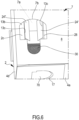
- the first and second locking tabs are engaged with the perimeter edge at respective folding edges, around which they are movable via rotation between the flat position in which they are parallel to and abutted against each other ( figure 3 ), and the tilted position in which they are relatively tilted and spaced from each other ( figure 6 ).
- first and second locking tabs 24', 24" are also configured for being constrained respectively with the first and second locking tabs 12b', 12b", preventing the exit of the latter from the through pocket 13a.
- the locking tabs 24 thus prevent a user from accessing the first coupling portion 12 and disengaging it from the second coupling portion 13.
- the container 1 can comprise a pair of second coupling portions 13 defined at corner portions of the abutment flap 2c defined at the second and of the fourth lateral wall 4c, 4d. Furthermore, the container 1 comprises a first pair of second coupling portions 13 defined along the first abutment flap, as well as a second pair of second coupling portions 13 defined on the second abutment flap; the pairs of second coupling portions 13 are arranged at a predetermined distance from each other, configured for effectively preventing a user from lifting the closure panel 8. In particular, the distance between a pair of second coupling portions is comprised between 15 cm and 30 cm.
- first and second coupling portions 12, 13, in the second operating position of the first coupling portion 12, are configured for defining a locking condition of the container in which said first and second coupling portions 12, 13 are stably engaged with each other in order to oppose the passage of the closure system 7 from the closed condition to the open one.
- the first coupling portion 12 comprises a removable portion configured for being separated from the closure system 7 during a first open condition of the container following the locking condition in order to provide evidence of a tampering of the container 1.
- the first coupling portion 12 is carried by the closure system 7; in detail, the first coupling portion 12 is engaged with the closure system 7 by means of a weakening portion 23 configured for being broken, following the definition of the locking condition, during the passage of the closure system 7 from the first closed condition to the first open condition.
- the removable portion defined by at least one part of the first coupling portion 12 is integrally joined to the closure system 7 by means of a connection flap having a plurality of notches adapted to allow the tearing (optionally facilitated) of the connection flap: the notched connection flap defines the weakening portion adapted to connect the removable portion (the first coupling portion 12) to the closure system 7.
- the removable portion defined by said first coupling portion 12 is engaged with the closure system 7 only by means of said weakening portion 23; the weakening portion 23 is configured for allowing a facilitated tearing of the first coupling portion 12 in a manner such that, even following a slight stress of the first coupling portion 12, the same weakening portion 23 can be broken and allow the separation of the first coupling portion 12, thus giving proof of an attempted tampering of the container 1.
- the first coupling portion 12 can be at least partly engaged with the closure system 7 at a plurality of weakening portions 23, the latter configured for being broken following the verification of a first open condition of the container in a manner such to define the removable portion.
- first coupling portion 12 is only engaged with the closure system 7 at the weakening portions 23, entirely defining the removable portion.
- the entire first coupling portion 12 is configured for being separated from the closure system 7, giving proof to a user of tampering of the container.
- a first coupling portion 12 comprising a base body 12c engaged with the closure system 7 at the perimeter edge of the through seat 7a, by means of the weakening portion 23.
- the central body 12a is engaged with the base body 12c by means of a folding edge 22 that is separate and spaced from the weakening portions 23: the folding edge 22 allows the rotation of the central body 12a in an independent manner with respect to the base body 12c.
- arranging a folding edge 22 spaced from the weakening portions 23 allows preventing the accidental breakage of the latter in step of folding of the first coupling portion 12 engaging with the second coupling portion 13.
- the base body 12c represents the element of the first coupling portion 12 connected to the closure system 7 by means of one or more weakened portions; the central body 12a, together with the at least one tab 12b, are integrally joined to the base body 12c and are foldable within the volume 3 of the container in order to define the locking condition.
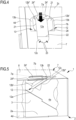
- the base body 12c is configured for remaining, both in the first and in the second operating position of the first coupling portion 12, outside the internal volume 3 while the central body 12a and the at least one tab 12b are foldable with respect to said base body 12c during the passage from the first to the second operating position ( figure 4 ) up to reaching a position inside the volume 3 ( figure 5 ).
- the at least one tab 12b is foldable with respect to the central body 12a around the folding edge 21 extended transversely to the folding edge 22 of the central body 12a, separate and spaced from the same folding edge 22.
- the step of folding of the first coupling portion 12 within the internal volume 3 is in fact visible, during which the tabs 12b', 12b" are folded around the edge 21 in order to allow the passage of the central body 12a and of the same tabs from the through pocket 13a; in such step, the central body 12a and the tabs are also folded with respect to the base body 12c around the folding edge 22.
- the tabs 12b are configured for being extended and stably engaged with the undercut portion 13b delimiting the through pocket 13a in order to lock the first coupling portion 12 within the volume 3.
- the first coupling portion 12 is configured for being separated (due to the presence of the weakened portion 23) from the same closure system 7 and be deposited within the second sub-chamber 45.
- the first coupling portion 12 thus removed can give evidence of a tampering of the container that took place, without coming into contact with the first sub-chamber 40 and in particular, with the food product contained therein.
- the second coupling portion 13 can further comprise a contrast portion 30 defined on the abutment flap 2c and/or on the intermediate flap 26 and arranged, during a first closed condition 7 of the container, below the exposed surface of the removable portion, in particular below the base body 12c.
- the contrast portion 30 defines an indicator visible through the through seat 7a of the closure system 7, configured for giving evidence of tampering of the container that occurred following the first open condition of the closure system 7.
- the contrast portion 30 can also comprise a signaling surface that is visibly different with respect to the abutment flap 2c and/or to the intermediate flap 26, configured for rendering the occurrence of the first open condition of the container even more evident to a user.
- the absence of the first removable portion 12 torn following the first open condition of the container 1 allows uncovering and rendering visible the contrast portion, which can visually signal (indicate) the absence of the first coupling portion 12, thus giving a user the possibility to quickly notice an attempt of tampering of the container 1.
- At least one between the support 2 and the closure system 7 can comprise at least one tear portion 9, 19 configured for allowing the breakage of said support 2 and/or closure system 7 during an attempt to open the container 1 itself when this is arranged in the locking condition.
- the support 2 comprising at least one tear portion 19 defined on at least the lateral wall of the support 2, in particular defined on the second and fourth lateral wall 4b, 4d.
- at least one of said lateral walls of the support can comprise a plurality of tear portions 19 each defined by one or more aligned notches adapted to define a weakened portion of the lateral wall.
- Such notches can for example be extended starting from the base 2a up to at the free edge 6 ( figure 6 ).
- each notch 19 can connect the base 2a with the slit 27 of the support adapted to receive the tongue 25 of the closure system.
- Such notches 19 are spaced and separated from the second coupling portion defined on the support 2 itself: the second coupling portions 13 are in fact placed at corner portions while the notches are arranged on the lateral walls of the support at a distance from the corner portions.
- the closure system 7 comprises, in a non-limiting manner, at least one tear portion 9, separate and spaced from the removable portion (i.e. separate and spaced from each first coupling portion): each tear portion 9 of the closure system 7 comprises at least one notch, optionally a plurality of notches aligned along a predetermined trajectory and placed one after the other, defined on the closure portion 8 and extended substantially starting from the perimeter edge of said closure portion.
- the closure system 7 can comprise a plurality of tear portions 9 configured for allowing the breakage of the closure system 7 itself during an attempt of access of a user in the locking condition of the container. Illustrated in the enclosed figures, in a non-limiting manner, is a closure system 7 comprising four tear portions 9 arranged, in pairs, at opposite sides of the closure system 7.
- each tear portion 9, 19 is positioned at a distance from the first and second coupling portions 12, 13, in particular at possible opening/access zones of the container.
- the tear portions 9, 19 are capable of giving evidence of an attempt of tampering of the container caused by an attempt to access inside the internal volume of the container without carrying out the normal opening of the same.
- the process provides for the arrangement of the support 2 which, as described above, is made of sheet material, optionally paper.
- the step provides for the arrangement of at least one first blank 50 of flat sheet material, comprising at least one central sheet 51 having a substantially quadrilateral, optionally square shape, at which at least one first lateral sheet 52 integrally joined to the central sheet 51 is engaged and emerging from the latter starting from the perimeter edge.
- the blank comprises a plurality of first lateral sheets 52 emerging for an entire perimeter edge of the central sheet 51.
- the process comprises a step of folding of each first lateral sheet 52 with respect to the central sheet 51 in a manner such that the latter defines the base 2a of the support 2, while the first lateral sheets 52 define the first, the second, the third and the fourth lateral wall 4a, 4b, 4c, 4d of the support.
- the first blank 50 can comprise at least one junction sheet 56 integrally joined to the first lateral sheets 52 defining the second and the fourth lateral wall 4b, 4d, at the longitudinal ends of the latter.
- the process can comprise a step of notching the junction sheet 56 in a manner such to make an opening 56a defining at least one tongue 56b.
- the step of notch of the junction sheet allows defining the locking tongue 70.
- the process further comprises a step of notching the first lateral sheet 52 defining the first lateral wall 4a and/or the first lateral sheet 52 defining the third lateral wall 4c, in a manner such to make at least one terminal opening 52a defining the air-vent opening 17.
- the process provides for the definition of the terminal opening 52a on said first lateral sheets 52 at the respective longitudinal ends adjacent to a tongue 56b of the terminal sheet 56.
- the process can also comprise a step of folding the terminal sheet 56 superimposed on a first lateral sheet 52 adjacent to the latter, as well as a step of engaging the tongue 56a within the terminal openings 52a, in a manner such to reach the stable three-dimensional configuration of the support.
- the blank 50 comprises a second lateral sheet 53 integrally joined to the first lateral sheet 52 on the side opposite the central sheet 51: the first lateral sheet 52 is thus interposed between said the central sheet 51 and the second lateral sheet 53.
- the latter is integrally joined to the second sheet 52 defining the first lateral wall 4a.
- the latter can comprise a plurality of third leaves 53, each of which integrally joined to the lateral sheets 52 defining the second and the fourth lateral wall 4b, 4d.
- the process can also comprise the attainment of a through notch 53a on the second lateral sheet 53 in a manner such to define the second coupling portion 13 and, in particular, the first and second locking tabs 24', 24".
- the process comprises a step of folding of each second sheet 53 with respect to the second lateral sheet with which they are engaged, in a manner such that the second lateral sheet 53 defines the abutment flap 2c of the support 2.
- the blank 50 can also comprise a third lateral sheet 55 integrally joined to a first lateral sheet 52 with which the second lateral sheet 53 is not engaged: the first lateral sheet 52 is then interposed between the central sheet 51 and the third lateral sheet 55.
- the process can further comprise a step of notching the fourth lateral sheet 55 in a manner such to make a separator 57 defining the slit 27.
- Such notching step in accordance with the first embodiment of the container shown in figure 1 , can also be made on the second lateral sheet 52 interposed between the central sheet 51 and the second lateral sheet 53.
- the process can also comprise a step of notching the third sheet 55, making through openings 55a, which define the display openings 28. It should be observed that the process can provide for a further step of folding the third lateral sheet 55 with respect to the first sheet 52 with which it is engaged in a manner such to define the intermediate flap 26.
- the process comprises a perimeter blank 54 in turn comprising a first auxiliary sheet 54a integrally joined to the third sheet 53 on the side opposite the second sheet 52.
- the blank 54 can further comprise a second auxiliary sheet 54b integrally joined to the first auxiliary sheet on the side opposite the third sheet 53.
- the first auxiliary sheet 54a can be interposed between the third sheet 53 and the second auxiliary sheet 54b.
- the process can then comprise a step of folding the first auxiliary sheet 54a with respect to the third sheet 53 in a manner such to define the separator 14, as well as a step of folding of the second auxiliary sheet 54b with respect to the first auxiliary sheet 51a.
- the process can then provide for a step of engaging the same second auxiliary sheet 54b with the central sheet 51 of the first blank, for example by means of gluing or mechanical interference, defining the first and the second sub-chamber 40, 45.
- the process can also comprise a step of notching executed on the first auxiliary sheet 54a in a manner such to make at least one through opening 154 defining the through access 16 of the separator 14.
- such notching step can provide for defining a plurality of through openings 154 that are separate and spaced from each other, each of which defining a through access 16.
- the process can further comprise the arrangement of a second blank 60 of sheet material, associable with the first blank 50.
- a second blank 60 of sheet material associable with the first blank 50. It should be observed that in the enclosed figures the second blank 60 is shown integrally joined to the first blank 50 to define a single flat blank. Nevertheless, it may be possible that the second blank 60 be separate and spaced from the first blank 50, in a manner such to substantially define a cover configured for being engaged with the latter.
- the second blank 60 can be integrally joined to a second lateral sheet 52 defining the third lateral wall 4c of the support, in a manner such that said second lateral sheet 52 is interposed between a central sheet 61 of the second blank 60 and the central sheet 51 of the first blank 50.
- the second blank 60 then comprises the central sheet 61 and at least one peripheral sheet 62 integrally joined to the central sheet 61.
- the process comprises a step of folding of each peripheral sheet 62 with respect to the central sheet 61 in a manner such to define the connection tongue 25.
- the process can provide for a step of folding each peripheral sheet 62 with respect to the central sheet 61 of the second blank, in a manner such to allow the insertion of the same peripheral sheet within the separator 57.
- the process comprises a step of notching the central sheet 61 of the second blank 60 in a manner such to make at least one notch 61b defining the first coupling portion 12.
- the process can provide for the execution of the latter step of notching the central sheet 61 of the second blank 60 in a manner such to make a plurality of first coupling portions 12.
- the process comprises a step of arranging at least one weakened section 61a defining the weakening sections 23 of the removable portion.
- the process provides for making a plurality of weakening sections at each notch 61a, defining a respective removable portion.
- the process can also comprise a step of folding of the central sheet 61 of the second blank with respect to the first lateral sheet 52 with which it is engaged, in a manner such to allow the superimposition of the central sheets 51, 61 respectively of the first and of the second blank 50, 60.
- the process provides for a step of inserting each peripheral sheet within a respective separator 57.
- the latter step in cooperation with the step of folding of the central sheet 61 of the second blank, allows achieving the closed condition of the closure system 7.
- a methid for closing a container in accordance with the above-reported description and/or with any one of the enclosed claims is also described.
- the method for closing the container 1 provides for arranging a container 1 in accordance with any one of the above-described embodiments.
- the method for closing the container 1 comprises a step of arranging the closure system 7 in the closed condition of the closure system 7.
- the closing method also provides for pushing, for example by means of a finger of a user, the first coupling portion 12 through the through pocket 13a of the second coupling portion 13, determining the rotation of the central body 13a with respect to the base body 13c, as well as the rotation of the first and of the second tab 12b', 12b" on the central body 13a.
- Such step then provides for inserting the second coupling portion 12 thus folded in the internal volume 3 of the support engaging the undercut portion 13b of the second coupling portion 13.
- the step of pushing the first coupling portion 12 through the through pocket 13a of the second coupling portion 13 further determines the movement of the first and of the second locking tab 24', 24" with respect to the abutment flap 2c towards a direction entering the through pocket 13a.
- the closing method can then provide for arranging the first and the second tab 12b', 12b" below the first and second locking tabs 24', 24" and engaging with the latter, in a manner such to reach the locking condition.
- the closing method furthermore provides for repeating the execution of the steps of insertingly pushing the first coupling portion 12 within the through pocket 13a of the second coupling portion 13, as well as of the step of engaging the same first coupling portion with the first and second locking tabs 24', 24".
Landscapes
- Engineering & Computer Science (AREA)
- Mechanical Engineering (AREA)
- Packages (AREA)
- Closures For Containers (AREA)
Claims (15)
- Récipient (1) à témoin d'effraction pour loger au moins un produit, par exemple un produit de type alimentaire, ledit récipient (1) comprenant :- un support (2) de matériau en feuille définissant un volume interne (3) configuré pour loger au moins un produit, ledit support (2) comprenant :∘ au moins une base (2a),∘ au moins une paroi latérale (4) émergeant de la base (2a) et délimitant, en coopération avec cette dernière, le volume interne (3), dans lequel ladite au moins une paroi latérale (4) définit, opposé à la base (2a), un bord libre (6),∘ au moins un rabat de butée (2c) émergeant d'au moins une section du bord libre (6) et faisant au moins partiellement face à la base (2a), dans lequel ledit au moins un rabat de butée (2c) délimite au moins partiellement une ouverture de passage (5) configurée pour placer en communication le volume interne (3) avec l'environnement externe,- au moins un système de fermeture (7), également de matériau en feuille, mobile par rapport au support (2) au moins entre :∘ un état fermé du récipient dans lequel le système de fermeture (7) est configuré pour empêcher la communication entre le volume interne (3) du support (2) et l'environnement externe, et∘ un état ouvert du récipient dans lequel le système de fermeture (7) est configuré pour permettre la communication entre le volume interne (3) et l'environnement externe,- au moins une première portion d'accouplement (12) portée par le système de fermeture (7),- au moins une seconde portion d'accouplement (13) définie sur le au moins un rabat de butée (2c), dans lequel ladite seconde portion d'accouplement (13) comprend au moins une poche traversante (13a) délimitée au moins partiellement par au moins une portion de contre-dépouille (13b),dans lequel, au moins durant un premier état fermé du récipient, la première portion d'accouplement (12) est mobile au moins entre :- une première position fonctionnelle dans laquelle la première portion d'accouplement (12) est désengagée de la seconde portion d'accouplement (13),- une seconde position fonctionnelle dans laquelle au moins une partie de la première portion d'accouplement (12) passe à travers la poche traversante (13a) et est agencée dans le volume interne (3), engageant la portion de contre-dépouille (13b),dans lequel la première et la seconde portion d'accouplement (12, 13), dans la seconde position fonctionnelle de la première portion d'accouplement (12), sont configurées pour définir un état de verrouillage,dans lequel la première portion d'accouplement (12) comprend :- au moins un corps central (12a),- au moins un onglet (12b) émergeant du corps central (12a) et qui se trouve, au moins dans la première position fonctionnelle de la première portion d'accouplement (12), au moins faisant face partiellement à la portion de contre-dépouille (13b) de la seconde portion d'accouplement (13), dans lequel ledit au moins un onglet (12b), au moins durant le passage de la première portion d'accouplement (12) depuis la première vers la seconde position fonctionnelle, est configuré pour être plié par rapport au corps central (12a) pour permettre le passage du au moins un onglet (12b) lui-même et d'au moins une partie du corps central (12a) à travers la poche traversante (13a), dans lequel ledit au moins un onglet (12b), dans la seconde position fonctionnelle de la première portion d'accouplement (12), est engagé de manière stable avec la portion de contre-dépouille (13b) définissant l'état de verrouillage,dans lequel le au moins un onglet (12b) est intégralement joint au corps central (12a) à l'aide d'un bord de pliage (21),dans lequel la portion de contre-dépouille (13b) de la seconde portion d'accouplement (13), durant le passage de la première portion d'accouplement (12) depuis la première vers la seconde position fonctionnelle, intercepte l'onglet (12b) pour permettre son pliage par rapport au corps central (12a), au niveau du bord de pliage (21),caractérisé en ce que, au moins une partie de la première portion d'accouplement (12) définit une portion amovible configurée pour être séparée du système de fermeture (7) durant un premier état ouvert du récipient, suite à l'état de verrouillage, afin de fournir une preuve d'effraction du récipient (1), dans lequel la portion amovible est intégralement jointe au système de fermeture (7) à l'aide d'au moins une portion d'affaiblissement (23) configurée pour être brisée durant le passage du système de fermeture (7) depuis le premier état fermé vers le premier état ouvert.
- Récipient selon la revendication précédente, dans lequel le corps central (12a) présente une taille inférieure à une zone de passage de la poche traversante (13a) de la seconde portion d'accouplement (13),
dans lequel le corps central (12a), dans le premier état fermé du récipient et dans la première position fonctionnelle de la première portion d'accouplement (12), fait face à la poche traversante (13a). - Récipient selon l'une quelconque des revendications précédentes, dans lequel l'onglet (12b), dans la seconde position fonctionnelle de la première portion d'accouplement (12), définit une portion respective de contre-dépouille de la première portion d'accouplement (12) elle-même faisant face à la portion de contre-dépouille (13b) de la seconde portion d'accouplement (13).
- Récipient selon l'une quelconque des revendications précédentes, dans lequel le corps central (12a) est sensiblement étendu le long d'un plan de développement tandis que le au moins un onglet (12b) est étendu le long d'un plan de développement respectif,dans lequel le corps central (12a) et ledit onglet (12b), au moins dans la première position fonctionnelle, sont sensiblement parallèles l'un par rapport à l'autre,dans lequel, dans la seconde position fonctionnelle, le plan de développement du au moins un onglet (12b) est incliné par rapport au plan de développement respectif du corps central (12a).
- Récipient selon l'une quelconque des revendications précédentes, dans lequel le au moins un onglet (12b) comprend un premier et un second onglet (12b', 12b") intégralement joints au corps central (12a) et agencés l'un opposé à l'autre par rapport au corps central (12a) lui-même, lesdits premier et second onglet (12a', 12a") étant configurés pour être pliés par rapport au corps central (12a), durant le passage de la première portion d'accouplement (12) depuis la première vers la seconde position fonctionnelle,
dans lequel le premier et le second onglet (12b', 12b"), dans la seconde position fonctionnelle de la première portion d'accouplement (12), définissent une forme sensiblement en « C » ou en « U » dont la concavité fait face au volume interne (3) et/ou au système de fermeture (7). - Récipient selon l'une quelconque des revendications précédentes, dans lequel la seconde portion d'accouplement (13) comprend au moins un onglet de verrouillage (24) émergeant de la portion de contre-dépouille (13b), fermant au moins partiellement la poche traversante (13a),dans lequel l'onglet de verrouillage (24), au moins dans le premier état fermé du récipient et au moins dans la première position fonctionnelle de la première portion d'accouplement (12), repose sensiblement parallèle au rabat de butée (2c),dans lequel l'onglet de verrouillage (24) est intégralement joint à la portion de sous-incision (13b) de la seconde portion d'accouplement (13) à l'aide d'au moins un bord de pliage respectif (13c),dans lequel le au moins un onglet de verrouillage (24), durant le passage de la première portion d'accouplement (12) depuis la première vers la seconde position fonctionnelle, est configuré pour être plié par rapport à la portion de contre-dépouille (13b) de la seconde portion d'accouplement (13), au moins partiellement dans le volume interne du support (2) pour permettre le passage d'au moins une partie de la première portion d'accouplement (12),dans lequel l'onglet de verrouillage (24), au moins dans l'état de verrouillage, fait sensiblement face à la portion du corps central (12a) de la première portion d'accouplement (12) agencée dans le volume interne (3) du support (2).
- Récipient selon la revendication 6, dans lequel l'onglet de verrouillage (24), au moins dans l'état de verrouillage, est sensiblement interposé entre la poche traversante (13a) de la seconde portion d'accouplement (13) et la au moins une partie de la première portion d'accouplement (12) agencée dans le volume interne (3) du support (2).
- Récipient selon l'une quelconque des revendications précédentes, dans lequel la première portion d'accouplement (12) comprend un corps de base (12c) intégralement joint au corps central (12a) à l'aide d'un bord de pliage (22) respectif, dans lequel le corps central (12a) de la première portion d'accouplement (12) est pliable par rapport au corps de base (12c) autour dudit bord de pliage (22) pour permettre au moins à une partie du corps central lui-même, durant le passage depuis la première vers la seconde position fonctionnelle, de passer à travers la poche traversante (13a) pour être agencée au moins partiellement dans le volume interne (3) du support.
- Récipient selon la revendication précédente, dans lequel la première portion d'accouplement (12), dans la seconde position fonctionnelle, est engagée avec le système de fermeture (7) uniquement à l'aide du corps de base (12c), dans lequel le corps de base (12c), dans la seconde position fonctionnelle, est engagé avec le système de fermeture (7) uniquement à l'aide de ladite portion d'affaiblissement (23),dans lequel le corps de base (12c), dans la seconde position fonctionnelle, est placé à l'extérieur du volume interne (3) du récipient (1) tandis que le corps central (12a) et le au moins un onglet (12b) sont placés dans le volume interne (3) s'engageant avec la seconde portion d'accouplement (13),dans lequel la portion amovible est définie par le corps de base (12c), par le corps central (12a) et par le au moins un onglet (12b) de la première portion d'accouplement (12).
- Récipient selon l'une quelconque des revendications précédentes, dans lequel le système de fermeture (7) présente un siège traversant (7a) délimité par un bord de périmètre (7b), éventuellement avec un profil fermé,
dans lequel la portion amovible est engagée avec au moins une section du bord de périmètre (7b) du siège traversant (7b) à l'aide de la au moins une portion d'affaiblissement (23), dans lequel ladite portion amovible, au moins dans la première position fonctionnelle, est agencée à l'intérieur dudit siège traversant (7a). - Récipient selon l'une quelconque des revendications précédentes, dans lequel le support (2) comprend au moins un rabat intermédiaire (26) émergeant d'au moins une section du bord libre (6) et faisant au moins partiellement face à la base (2a), dans lequel ledit au moins un rabat intermédiaire (26) délimite au moins partiellement une ouverture de passage (5) configurée pour placer en communication le volume interne (3) avec l'environnement externe,
dans lequel le rabat intermédiaire (26) est configuré pour être au moins partiellement surimposé sur le rabat de butée (2c) et être interposé, dans l'état fermé du récipient (1), entre une portion du rabat de butée (2c) et une portion du système de fermeture (7). - Récipient selon la revendication 11, dans lequel le rabat intermédiaire (26) présente une ouverture traversante (28) délimitée par un bord de périmètre, éventuellement avec un profil fermé, qui, au moins dans le premier état fermé et dans le premier état ouvert du récipient, fait face à la poche traversante (13a) de la seconde portion d'accouplement (13),
dans lequel ladite ouverture traversante (28) du rabat intermédiaire (26) étant configurée pour permettre le passage de la première portion d'accouplement (12), durant le passage de cette dernière depuis la première vers la seconde position fonctionnelle, pour permettre à ladite première portion d'engagement (12) de passer à travers la poche traversante (13a) et d'engager la portion de contre-dépouille (13b) de la seconde portion d'accouplement (13). - Récipient selon l'une quelconque des revendications précédentes, dans lequel la au moins une paroi latérale (4) du support (2) présente au moins une ouverture de ventilation d'air (17) configurée pour permettre, au moins dans l'état fermé du récipient, la communication fluidique entre le volume interne (3) et l'environnement externe, éventuellement pour permettre à l'air présent dans le volume interne d'être ventilé à l'extérieur du récipient (1).
- Récipient selon l'une quelconque des revendications précédentes, comprenant au moins un séparateur (14) qui raccorde le rabat de butée (2c) à la base (2a) du support (2), ledit séparateur étant étendu dans le volume interne (3) du support (2) et étant configuré pour diviser une zone centrale du support adaptée pour recevoir le produit depuis une zone périphérique du support au niveau de laquelle le rabat de butée (2c) est présent,éventuellement le séparateur (14) est intégralement joint et plié par rapport au rabat de butée (2c) au niveau du bord d'extrémité (6a),dans lequel le rabat de butée (2c) est étendu dans la longueur le long du bord libre (6) du support (2),dans lequel le séparateur (14) est étendu dans la longueur sensiblement sur la longueur entière du rabat de butée (2c) pour définir sensiblement un canal, éventuellement placé au niveau d'une zone périphérique du support (2),dans lequel le séparateur (14) est configuré pour diviser le volume interne (3) du support en une première et une seconde sous-chambre (40, 45), dans lequel la première sous-chambre (40) définit ladite au moins une zone centrale du support (2) adaptée pour recevoir le produit tandis que la seconde sous-chambre (45) est délimitée par le canal et est agencée au niveau d'une zone périphérique du support (2),dans lequel le séparateur (14) est agencé en faisant au moins partiellement face à l'ouverture de ventilation d'air (17).
- Procédé de fabrication d'un récipient (1) selon l'une quelconque des revendications précédentes, ledit procédé comprenant les étapes suivantes consistant à :- disposer au moins un premier flan (50) de matériau en feuille étendu le long d'un plan, ledit premier flan (50) comprenant :∘ une feuille centrale (51),∘ au moins une première feuille latérale (52) intégralement jointe à la feuille centrale (51) et émergeant de la dernière en commençant depuis un bord de périmètre,∘ au moins une seconde feuille latérale (53) intégralement jointe à la première feuille latérale sur le côté opposé à la feuille centrale (51), dans lequel ladite première feuille latérale (52) est interposée entre ladite feuille centrale (51) et ladite seconde feuille latérale,- disposer le système de fermeture (7) à l'aide d'au moins un second flan (60) de matériau en feuille étendu le long d'un plan,dans lequel le procédé comprend les étapes consistant à :- plier la au moins une première feuille latérale (52) du premier flan par rapport à la feuille centrale (51) d'une manière telle que ladite feuille centrale (51) du premier flan (50) définit la base (2a) du support (2) tandis que la au moins une première feuille latérale (52) définit la au moins une paroi latérale du support (2),- plier la au moins une seconde feuille latérale (53) du premier flan par rapport à la première feuille latérale (52) d'une manière telle que ladite seconde feuille latérale (53) définit le rabat de butée (2c) du support (2),dans lequel le procédé comprend également les étapes consistant à :- définir, sur le système de fermeture, la au moins une première portion d'accouplement (12),- définir, sur le rabat de butée (2c), la au moins une seconde portion d'accouplement (13), et agencer au moins une section d'affaiblissement (61a) définissant les sections d'affaiblissement (23) de la portion amovible (12).
Applications Claiming Priority (2)
| Application Number | Priority Date | Filing Date | Title |
|---|---|---|---|
| IT202000027756 | 2020-11-19 | ||
| IT202000027753 | 2020-11-19 |
Publications (3)
| Publication Number | Publication Date |
|---|---|
| EP4001148A1 EP4001148A1 (fr) | 2022-05-25 |
| EP4001148C0 EP4001148C0 (fr) | 2025-01-22 |
| EP4001148B1 true EP4001148B1 (fr) | 2025-01-22 |
Family
ID=78536138
Family Applications (1)
| Application Number | Title | Priority Date | Filing Date |
|---|---|---|---|
| EP21208641.7A Active EP4001148B1 (fr) | 2020-11-19 | 2021-11-16 | Récipient et son procédé de fabrication |
Country Status (2)
| Country | Link |
|---|---|
| US (1) | US11767144B2 (fr) |
| EP (1) | EP4001148B1 (fr) |
Families Citing this family (9)
| Publication number | Priority date | Publication date | Assignee | Title |
|---|---|---|---|---|
| US11511921B1 (en) * | 2019-07-19 | 2022-11-29 | Todd Wikstrom | Tamper-evident container lock |
| EP4182237A4 (fr) * | 2020-07-17 | 2024-08-28 | Pizza Spice Packet LLC | Fermeture de contenant inviolable |
| US12258180B2 (en) * | 2020-10-19 | 2025-03-25 | Alexander Yambao | Tamper resistant storage and transport system for food |
| IT202100001283A1 (it) * | 2021-01-25 | 2022-07-25 | Igb Srl | Contenitore per l’alloggiamento di almeno un prodotto, procedimento per la realizzazione dello stesso e metodo di chiusura di detto contenitore |
| IT202100024749A1 (it) * | 2021-09-28 | 2023-03-28 | Jerzy Crespi | Scatola per pizza e fustellato |
| WO2024178165A1 (fr) * | 2023-02-24 | 2024-08-29 | Graphic Packaging International, Llc | Récipient avec couvercle |
| EP4491528A1 (fr) * | 2023-07-11 | 2025-01-15 | AR.CA Box Pizza SNC di Cognolato Katia & C. | Boîte à pizza avec éléments d'étanchéité ou joints |
| WO2025032429A1 (fr) * | 2023-08-04 | 2025-02-13 | Tiber Pack S.P.A. | Appareil de fermeture d'un emballage et procédé de fermeture d'un emballage |
| US20250153890A1 (en) * | 2023-11-13 | 2025-05-15 | Giuseppe Petix | self-locking boxes |
Citations (1)
| Publication number | Priority date | Publication date | Assignee | Title |
|---|---|---|---|---|
| DE202009003994U1 (de) * | 2009-03-25 | 2009-06-18 | Mb Karton Ernst Behrend Gmbh | Faltkarton mit Aufreißperforation |
Family Cites Families (23)
| Publication number | Priority date | Publication date | Assignee | Title |
|---|---|---|---|---|
| GB817223A (en) | 1956-08-27 | 1959-07-29 | Davidson & Sons Ltd C | Fibreboard blanks for cartons |
| US1341429A (en) * | 1916-03-22 | 1920-05-25 | Charles W Lewis | Collapsible box |
| US2026417A (en) * | 1934-03-19 | 1935-12-31 | Eddy Paper Corp | Shipping container |
| BE410524A (fr) | 1935-01-16 | 1935-08-31 | Georges Minidre | Fermeture inviolable pour boites pliantes en carton, et paquetages similaires |
| US2349707A (en) * | 1942-09-19 | 1944-05-23 | Container Corp | Container lock |
| US2698125A (en) * | 1953-06-18 | 1954-12-28 | Nat Container Corp | Container |
| AT252706B (de) * | 1962-01-13 | 1967-03-10 | Agfa Ag | Zuschnitt, vorzugsweise aus Karton für ein auf der Rückseite zu umrahmendes Bild |
| US3368735A (en) * | 1966-09-06 | 1968-02-13 | Hans L. Levi | Five panel folder with cushion ends |
| US3541052A (en) * | 1968-10-15 | 1970-11-17 | Anaconda American Brass Co | Unitary carton and reusable shipping package therefor |
| DE8324259U1 (de) | 1983-08-24 | 1984-01-19 | Horst GmbH Druck & Verpackung, 6450 Hanau | Faltschachtel zum Verpacken von vorzugsweisen flachen Gegenstaenden |
| US4830270A (en) * | 1988-05-19 | 1989-05-16 | Professional Packaging Limited | Mailing and shipping carton |
| US5211329A (en) * | 1992-06-25 | 1993-05-18 | Bates Container, Inc. | Food product container |
| US5240176A (en) | 1992-08-07 | 1993-08-31 | International Paper Company | Paperboard hospital waste container |
| US5328080A (en) * | 1993-02-08 | 1994-07-12 | The Mead Corporation | Panel interlocking arrangement for wraparound carrier |
| US5950912A (en) | 1998-05-14 | 1999-09-14 | Economopoulos; Demosthenes O. | Dual pizza pie box |
| DE20300032U1 (de) | 2003-01-03 | 2003-04-17 | Fricke, Reinhard, 59759 Arnsberg | Stapelbarer Transportbehälter aus Wellpappe und Zuschnitt dafür |
| US20070170234A1 (en) * | 2006-01-25 | 2007-07-26 | Meadwestvaco Peckaging Systems, | Carton having locking feature suitable for hand-packing |
| EP2354020B1 (fr) | 2010-01-28 | 2012-11-14 | Rondo AG | Boîte, notamment boîte pliante |
| US9290290B2 (en) * | 2014-03-04 | 2016-03-22 | Inteplast Group Corporation | Reusable box blank |
| US20170341803A1 (en) | 2014-10-22 | 2017-11-30 | Francesco Felice MARINCOLA | Package for take-away food products, in particular for pizza |
| BE1024776B1 (nl) | 2017-04-10 | 2018-06-26 | I.C.B. N.V. | Gevouwen, afgedichte, herbruikbare, lijmloze, lekbestendige bereidingsrecipiënt die opbergbaar is als plat vel |
| US10633140B1 (en) * | 2017-04-21 | 2020-04-28 | Surpack s.a. | Boxes, blanks and associated methods |
| US20190344927A1 (en) * | 2018-05-08 | 2019-11-14 | Huseyin Hayri Kamiloglu | Lockable box and blank for forming the same |
-
2021
- 2021-11-16 EP EP21208641.7A patent/EP4001148B1/fr active Active
- 2021-11-19 US US17/530,904 patent/US11767144B2/en active Active
Patent Citations (1)
| Publication number | Priority date | Publication date | Assignee | Title |
|---|---|---|---|---|
| DE202009003994U1 (de) * | 2009-03-25 | 2009-06-18 | Mb Karton Ernst Behrend Gmbh | Faltkarton mit Aufreißperforation |
Also Published As
| Publication number | Publication date |
|---|---|
| US20220153510A1 (en) | 2022-05-19 |
| EP4001148C0 (fr) | 2025-01-22 |
| US11767144B2 (en) | 2023-09-26 |
| EP4001148A1 (fr) | 2022-05-25 |
Similar Documents
| Publication | Publication Date | Title |
|---|---|---|
| EP4001148B1 (fr) | Récipient et son procédé de fabrication | |
| EP2377767B1 (fr) | Carton d'aliments extensible | |
| CA1271174A (fr) | Cartonnage debiteur d'articles, et son ebauche | |
| RU2401229C2 (ru) | Устойчивый к вскрытию контейнер с индикацией вскрытия и способ образования данного контейнера | |
| US9211970B2 (en) | Food tray | |
| US12116185B2 (en) | Dual cell, efficient box with top slide openings and view windows | |
| CA3158955C (fr) | Cartons empilables, systeme, et leurs procedes d'utilisation | |
| US4350281A (en) | One-piece shipping container with cut-case protection | |
| WO2015066474A1 (fr) | Barquette alimentaire à deux compartiments | |
| US12497208B2 (en) | Tamper-evident container having release flap and closure tab | |
| CA2391211A1 (fr) | Boite en carton munie d'un couvercle integre en carton presentant une charniere sur le couvercle | |
| US20030062406A1 (en) | Container for carrying hot pizzas and the like | |
| US4209095A (en) | Closure for blister card type container | |
| KR20170095838A (ko) | 폐쇄 플랩을 구비한 접근 개구부를 포함하는 패키지 | |
| US7097093B2 (en) | Carton opening feature | |
| EP4036023A1 (fr) | Récipient destiné à recevoir au moins un produit et son procédé de fabrication | |
| US12234065B2 (en) | Tray for transport and storage of products and method for use thereof | |
| EP3354584B1 (fr) | Récipient inviolable et son procédé de fabrication | |
| US7980453B2 (en) | Apparatus and method for handles integrated with product containers | |
| US20220033135A1 (en) | Tamper-evident box for edible contents | |
| EP3406533A1 (fr) | Emballage inviolable et feuille de matériau flexible pour ledit emballage | |
| NZ521445A (en) | Fumigatable trays | |
| BR202022001680Y1 (pt) | Disposição introduzida em embalagem com vértices reentrantes para produtos de panificação | |
| EP3317211A1 (fr) | Emballage pour produits de confiserie et son procédé de formation | |
| BR202022001680U2 (pt) | Disposição introduzida em embalagem com vértices reentrantes para produtos de panificação |
Legal Events
| Date | Code | Title | Description |
|---|---|---|---|
| PUAI | Public reference made under article 153(3) epc to a published international application that has entered the european phase |
Free format text: ORIGINAL CODE: 0009012 |
|
| STAA | Information on the status of an ep patent application or granted ep patent |
Free format text: STATUS: THE APPLICATION HAS BEEN PUBLISHED |
|
| AK | Designated contracting states |
Kind code of ref document: A1 Designated state(s): AL AT BE BG CH CY CZ DE DK EE ES FI FR GB GR HR HU IE IS IT LI LT LU LV MC MK MT NL NO PL PT RO RS SE SI SK SM TR |
|
| STAA | Information on the status of an ep patent application or granted ep patent |
Free format text: STATUS: REQUEST FOR EXAMINATION WAS MADE |
|
| 17P | Request for examination filed |
Effective date: 20220706 |
|
| RBV | Designated contracting states (corrected) |
Designated state(s): AL AT BE BG CH CY CZ DE DK EE ES FI FR GB GR HR HU IE IS IT LI LT LU LV MC MK MT NL NO PL PT RO RS SE SI SK SM TR |
|
| P01 | Opt-out of the competence of the unified patent court (upc) registered |
Effective date: 20230510 |
|
| STAA | Information on the status of an ep patent application or granted ep patent |
Free format text: STATUS: EXAMINATION IS IN PROGRESS |
|
| 17Q | First examination report despatched |
Effective date: 20230802 |
|
| GRAP | Despatch of communication of intention to grant a patent |
Free format text: ORIGINAL CODE: EPIDOSNIGR1 |
|
| STAA | Information on the status of an ep patent application or granted ep patent |
Free format text: STATUS: GRANT OF PATENT IS INTENDED |
|
| INTG | Intention to grant announced |
Effective date: 20240916 |
|
| GRAS | Grant fee paid |
Free format text: ORIGINAL CODE: EPIDOSNIGR3 |
|
| GRAA | (expected) grant |
Free format text: ORIGINAL CODE: 0009210 |
|
| STAA | Information on the status of an ep patent application or granted ep patent |
Free format text: STATUS: THE PATENT HAS BEEN GRANTED |
|
| AK | Designated contracting states |
Kind code of ref document: B1 Designated state(s): AL AT BE BG CH CY CZ DE DK EE ES FI FR GB GR HR HU IE IS IT LI LT LU LV MC MK MT NL NO PL PT RO RS SE SI SK SM TR |
|
| REG | Reference to a national code |
Ref country code: GB Ref legal event code: FG4D |
|
| REG | Reference to a national code |
Ref country code: CH Ref legal event code: EP |
|
| REG | Reference to a national code |
Ref country code: IE Ref legal event code: FG4D |
|
| REG | Reference to a national code |
Ref country code: DE Ref legal event code: R096 Ref document number: 602021025108 Country of ref document: DE |
|
| U01 | Request for unitary effect filed |
Effective date: 20250219 |
|
| U07 | Unitary effect registered |
Designated state(s): AT BE BG DE DK EE FI FR IT LT LU LV MT NL PT RO SE SI Effective date: 20250225 |
|
| P04 | Withdrawal of opt-out of the competence of the unified patent court (upc) registered |
Free format text: CASE NUMBER: APP_8871/2025 Effective date: 20250221 |
|
| PG25 | Lapsed in a contracting state [announced via postgrant information from national office to epo] |
Ref country code: RS Free format text: LAPSE BECAUSE OF FAILURE TO SUBMIT A TRANSLATION OF THE DESCRIPTION OR TO PAY THE FEE WITHIN THE PRESCRIBED TIME-LIMIT Effective date: 20250422 |
|
| PG25 | Lapsed in a contracting state [announced via postgrant information from national office to epo] |
Ref country code: PL Free format text: LAPSE BECAUSE OF FAILURE TO SUBMIT A TRANSLATION OF THE DESCRIPTION OR TO PAY THE FEE WITHIN THE PRESCRIBED TIME-LIMIT Effective date: 20250122 |
|
| PG25 | Lapsed in a contracting state [announced via postgrant information from national office to epo] |
Ref country code: ES Free format text: LAPSE BECAUSE OF FAILURE TO SUBMIT A TRANSLATION OF THE DESCRIPTION OR TO PAY THE FEE WITHIN THE PRESCRIBED TIME-LIMIT Effective date: 20250122 |
|
| PG25 | Lapsed in a contracting state [announced via postgrant information from national office to epo] |
Ref country code: NO Free format text: LAPSE BECAUSE OF FAILURE TO SUBMIT A TRANSLATION OF THE DESCRIPTION OR TO PAY THE FEE WITHIN THE PRESCRIBED TIME-LIMIT Effective date: 20250422 Ref country code: IS Free format text: LAPSE BECAUSE OF FAILURE TO SUBMIT A TRANSLATION OF THE DESCRIPTION OR TO PAY THE FEE WITHIN THE PRESCRIBED TIME-LIMIT Effective date: 20250522 |
|
| PG25 | Lapsed in a contracting state [announced via postgrant information from national office to epo] |
Ref country code: HR Free format text: LAPSE BECAUSE OF FAILURE TO SUBMIT A TRANSLATION OF THE DESCRIPTION OR TO PAY THE FEE WITHIN THE PRESCRIBED TIME-LIMIT Effective date: 20250122 |
|
| PG25 | Lapsed in a contracting state [announced via postgrant information from national office to epo] |
Ref country code: GR Free format text: LAPSE BECAUSE OF FAILURE TO SUBMIT A TRANSLATION OF THE DESCRIPTION OR TO PAY THE FEE WITHIN THE PRESCRIBED TIME-LIMIT Effective date: 20250423 |
|
| PG25 | Lapsed in a contracting state [announced via postgrant information from national office to epo] |
Ref country code: SM Free format text: LAPSE BECAUSE OF FAILURE TO SUBMIT A TRANSLATION OF THE DESCRIPTION OR TO PAY THE FEE WITHIN THE PRESCRIBED TIME-LIMIT Effective date: 20250122 |
|
| PG25 | Lapsed in a contracting state [announced via postgrant information from national office to epo] |
Ref country code: CZ Free format text: LAPSE BECAUSE OF FAILURE TO SUBMIT A TRANSLATION OF THE DESCRIPTION OR TO PAY THE FEE WITHIN THE PRESCRIBED TIME-LIMIT Effective date: 20250122 |
|
| PG25 | Lapsed in a contracting state [announced via postgrant information from national office to epo] |
Ref country code: SK Free format text: LAPSE BECAUSE OF FAILURE TO SUBMIT A TRANSLATION OF THE DESCRIPTION OR TO PAY THE FEE WITHIN THE PRESCRIBED TIME-LIMIT Effective date: 20250122 |
|
| PLBE | No opposition filed within time limit |
Free format text: ORIGINAL CODE: 0009261 |
|
| STAA | Information on the status of an ep patent application or granted ep patent |
Free format text: STATUS: NO OPPOSITION FILED WITHIN TIME LIMIT |
|
| 26N | No opposition filed |
Effective date: 20251023 |