EP4001149A1 - Dispositif d'ouverture pour un emballage et emballage pourvu d'un dispositif d'ouverture - Google Patents
Dispositif d'ouverture pour un emballage et emballage pourvu d'un dispositif d'ouverture Download PDFInfo
- Publication number
- EP4001149A1 EP4001149A1 EP20207708.7A EP20207708A EP4001149A1 EP 4001149 A1 EP4001149 A1 EP 4001149A1 EP 20207708 A EP20207708 A EP 20207708A EP 4001149 A1 EP4001149 A1 EP 4001149A1
- Authority
- EP
- European Patent Office
- Prior art keywords
- covering element
- opening device
- opening
- main body
- open position
- Prior art date
- Legal status (The legal status is an assumption and is not a legal conclusion. Google has not performed a legal analysis and makes no representation as to the accuracy of the status listed.)
- Withdrawn
Links
- 230000008878 coupling Effects 0.000 claims abstract description 11
- 238000010168 coupling process Methods 0.000 claims abstract description 11
- 238000005859 coupling reaction Methods 0.000 claims abstract description 11
- 239000005022 packaging material Substances 0.000 claims description 17
- 239000011091 composite packaging material Substances 0.000 claims description 2
- 239000000463 material Substances 0.000 description 10
- 235000013305 food Nutrition 0.000 description 8
- 239000004033 plastic Substances 0.000 description 7
- 229920003023 plastic Polymers 0.000 description 7
- 239000012528 membrane Substances 0.000 description 5
- 239000002657 fibrous material Substances 0.000 description 4
- 238000007789 sealing Methods 0.000 description 4
- 239000004698 Polyethylene Substances 0.000 description 2
- XAGFODPZIPBFFR-UHFFFAOYSA-N aluminium Chemical compound [Al] XAGFODPZIPBFFR-UHFFFAOYSA-N 0.000 description 2
- 229910052782 aluminium Inorganic materials 0.000 description 2
- 239000011888 foil Substances 0.000 description 2
- -1 polyethylene Polymers 0.000 description 2
- 229920000573 polyethylene Polymers 0.000 description 2
- 235000007688 Lycopersicon esculentum Nutrition 0.000 description 1
- 240000003768 Solanum lycopersicum Species 0.000 description 1
- 238000004026 adhesive bonding Methods 0.000 description 1
- 239000011111 cardboard Substances 0.000 description 1
- 239000002131 composite material Substances 0.000 description 1
- 230000001419 dependent effect Effects 0.000 description 1
- 239000004715 ethylene vinyl alcohol Substances 0.000 description 1
- 235000015203 fruit juice Nutrition 0.000 description 1
- 238000000034 method Methods 0.000 description 1
- 235000013336 milk Nutrition 0.000 description 1
- 239000008267 milk Substances 0.000 description 1
- 210000004080 milk Anatomy 0.000 description 1
- 238000000465 moulding Methods 0.000 description 1
- 238000004806 packaging method and process Methods 0.000 description 1
- 239000000123 paper Substances 0.000 description 1
- 239000011087 paperboard Substances 0.000 description 1
- 235000015067 sauces Nutrition 0.000 description 1
- 238000011144 upstream manufacturing Methods 0.000 description 1
- 235000014101 wine Nutrition 0.000 description 1
Images
Classifications
-
- B—PERFORMING OPERATIONS; TRANSPORTING
- B65—CONVEYING; PACKING; STORING; HANDLING THIN OR FILAMENTARY MATERIAL
- B65D—CONTAINERS FOR STORAGE OR TRANSPORT OF ARTICLES OR MATERIALS, e.g. BAGS, BARRELS, BOTTLES, BOXES, CANS, CARTONS, CRATES, DRUMS, JARS, TANKS, HOPPERS, FORWARDING CONTAINERS; ACCESSORIES, CLOSURES, OR FITTINGS THEREFOR; PACKAGING ELEMENTS; PACKAGES
- B65D5/00—Rigid or semi-rigid containers of polygonal cross-section, e.g. boxes, cartons or trays, formed by folding or erecting one or more blanks made of paper
- B65D5/42—Details of containers or of foldable or erectable container blanks
- B65D5/72—Contents-dispensing means
- B65D5/74—Spouts
- B65D5/746—Spouts formed separately from the container
- B65D5/747—Spouts formed separately from the container with means for piercing or cutting the container wall or a membrane connected to said wall
- B65D5/749—Spouts formed separately from the container with means for piercing or cutting the container wall or a membrane connected to said wall a major part of the container wall or membrane being removed from the container after the opening
-
- B—PERFORMING OPERATIONS; TRANSPORTING
- B65—CONVEYING; PACKING; STORING; HANDLING THIN OR FILAMENTARY MATERIAL
- B65D—CONTAINERS FOR STORAGE OR TRANSPORT OF ARTICLES OR MATERIALS, e.g. BAGS, BARRELS, BOTTLES, BOXES, CANS, CARTONS, CRATES, DRUMS, JARS, TANKS, HOPPERS, FORWARDING CONTAINERS; ACCESSORIES, CLOSURES, OR FITTINGS THEREFOR; PACKAGING ELEMENTS; PACKAGES
- B65D47/00—Closures with filling and discharging, or with discharging, devices
- B65D47/04—Closures with discharging devices other than pumps
- B65D47/06—Closures with discharging devices other than pumps with pouring spouts or tubes; with discharge nozzles or passages
- B65D47/08—Closures with discharging devices other than pumps with pouring spouts or tubes; with discharge nozzles or passages having articulated or hinged closures
- B65D47/0804—Closures with discharging devices other than pumps with pouring spouts or tubes; with discharge nozzles or passages having articulated or hinged closures integrally formed with the base element provided with the spout or discharge passage
- B65D47/0833—Hinges without elastic bias
- B65D47/0847—Hinges without elastic bias located within a flat surface of the base element
- B65D47/0852—Hinges without elastic bias located within a flat surface of the base element consisting of a strap of flexible material
Definitions
- the present invention relates to an opening device for a package, in particular a package having a main body, filled with a pourable product, even more particular filled with a pourable food product.
- the present invention also relates to a package, in particular a package having a main body, filled with a pourable product, even more particular filled with a pourable food product, and having an opening device.
- pourable food products such as fruit juice, UHT (ultra-high-temperature treated) milk, wine, tomato sauce, etc.
- packages in particular sealed packages, made of sterilized packaging material.
- a typical example is the parallelepiped-shaped package for pourable food products known as Tetra Brik Aseptic (registered trademark), which is made by sealing and folding a laminated strip packaging material.
- the packaging material has a multilayer structure comprising a carton and/or paper base layer, covered on both sides with layers of heat-seal plastic material, e.g. polyethylene.
- the packaging material also comprises a layer of oxygen-barrier material, e.g. an aluminum foil, which is superimposed on a layer of heat-seal plastic material, and is in turn covered with another layer of heat-seal plastic material forming the inner face of the package eventually contacting the food product.
- Some known packages comprise each a sealed main body having a designated pour opening and an opening device arranged on the main body and designed to close the designated pour opening at least prior to the first use.
- Some known opening devices comprise a strap, which seals the designated pour opening and which needs to be removed from the main body prior to the first use of the package.
- opening devices also comprise a collar arranged about the designated pour opening and a lid, which can be selectively coupled or uncoupled from the collar. In these cases, prior to the first use, the lid needs to be removed from the collar and then the user can access and remove the strap.
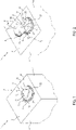
- Number 1 indicates as a whole a package comprising:
- main body 2 is obtained from a packaging material, in particular a composite packaging material, having a multilayer structure (not shown and known as such).
- the packaging material is provided in the form of a web.
- main body 2 is obtained by forming a tube from the packaging material, longitudinally sealing the tube, filling the tube with the pourable product and by transversally sealing and cutting the tube.
- the packaging material comprises at least one layer of fibrous material, such as e.g. paper or cardboard, and at least two layers of heat-seal plastic material, e.g. polyethylene, interposing the layer of fibrous material in between one another.
- fibrous material such as e.g. paper or cardboard
- heat-seal plastic material e.g. polyethylene
- the packaging material may also comprise a layer of gas- and light-barrier material, e.g. aluminum foil or ethylene vinyl alcohol (EVOH) film, in particular being arranged between one of the layers of the heat-seal plastic material and the layer of fibrous material.
- the packaging material also comprises a further layer of heat-seal plastic material being interposed between the layer of gas- and light-barrier material and the layer of fibrous material.
- opening device(s) 3 is/are applied to the packaging material prior to arranging the packaging material within or during advancement of the packaging material through a packaging machine for forming, filling and sealing main bodies 2 from the packaging material carrying opening devices 3.
- opening device(s) 3 could be applied onto main body(ies) 2.
- opening devices 3 may occur by means of a molding process and/or adhesive bonding and/or ultrasonic bonding.
- opening devices 3 may be molded in a single piece, in particular onto the packaging material and/or main body(ies) 2.
- main body 2 extends along a longitudinal axis, a first transversal axis and a second transversal axis.
- the extension of package 1 along the longitudinal axis is larger than the extension of package 1 along the first transversal axis and the second transversal axis.
- main body 2 is parallelepiped-shaped.
- main body 2 may comprise a first wall portion, in particular being transversal, even more particular perpendicular, to the longitudinal axis, from which main body 2 extends along the longitudinal axis.
- the first wall portion defines a support surface of package 1, in particular of main body 2, which is designed to be put in contact with a support, such as e.g. a shelf, when, in use, being e.g. exposed within a sales point or when being stored.
- a support such as e.g. a shelf
- the first wall portion defines a bottom wall portion of main body 2 and/or package 1.
- main body 2 may also comprise a plurality of lateral walls 4 being (fixedly) connected to the first wall portion and extending, in particular substantially parallel to the longitudinal axis, from the first wall portion.
- main body 2 may also comprise a second wall portion 5 opposite to the first wall portion and being (fixedly) connected to at least some of lateral walls 4.
- lateral walls 4 are interposed between the first wall portion and second wall portion 5.
- main body 2 when main body 2 is arranged on a support second wall portion 5 defines a top wall portion.
- first wall portion and second wall portion 5 are inclined with respect to one another (i.e. the first wall portion and second wall portion 5 are not parallel to one another).
- first wall portion and second wall portion 5 are not parallel to one another.
- second wall portion 5 is inclined with respect to the first wall portion and the support.
- first wall portion and second wall portion 5 may be parallel to one another.
- second wall portion 5 carries and/or comprises the designated pour opening and opening device 3 is mounted to second wall portion 5.
- package 1 in particular main body 2, comprises an inner space configured to contain and/or containing the pourable product.
- opening device 3 comprises at least:
- opening device 3 may comprise a collar 8 connected to and extending away from base frame 6, in particular along a longitudinal axis A.
- longitudinal axis A is perpendicular to base frame 6.
- opening device 3 may comprise a gripping tab, or ring 9 (integrally) connected to covering element 7, in particular designed for allowing and/or facilitating manipulation of covering element 7.
- covering element 7 is hinged to base frame 6 and is movable around a respective hinge axis B.
- hinge axis B being defined by the hinge hinging covering element 7 to base frame 6.
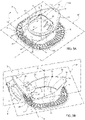
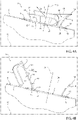
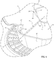
- covering element 7 is angularly movable around hinge axis B between a closed position (see Figures 3a and 4a ) in which covering element 7 closes and/or is designed to close the designated pour opening and an open position (see Figures 3b , 4b and 5 ) in which covering element 7 opens and/or is configured to open the designated pour opening.
- covering element 7 may be in a first angular position and a second angular position with respect to hinge axis B when being respectively in the closed position and the open position.
- covering element 7 is movable along an opening direction D1 and a closing direction D2 opposite to opening direction D1 for moving covering element 7 from respectively the closed position to the open position and from the open position to the closed position.
- gripping ring 9 is, in use, gripped by a consumer for moving covering element 7 between the closed position and the open position.
- covering element 7 may be repeatedly moved between the closed position and the open position.
- opening device 3 may also comprise a retaining group 10 configured to retain covering element 7 in the open position (in the second angular position), i.e. retaining group 10 is designed to impede and/or obstacle covering element 7 to (unwantedly) move from the open position to the closed position.
- a retaining group 10 configured to retain covering element 7 in the open position (in the second angular position), i.e. retaining group 10 is designed to impede and/or obstacle covering element 7 to (unwantedly) move from the open position to the closed position.
- retaining group 10 may be connected to, in particular is integral to, collar 8.
- retaining group 10 may be designed such to exert a retaining force on covering element 7 such that movement of covering element 7 from the open position to the closed position and/or along second direction D2 is obstructed. Furthermore, retaining group 10 may be designed to allow movement of covering element 7 from the open position to the closed position and/or along second direction D2 in the case that a force acts on covering element 7, which is larger than the retaining force.
- base frame 6 comprises an opening 13, in particular being designed and/or being aligned with respect to and/or delimiting and/or being designed to delimit the designated pour opening.
- covering element 7 is configured to close and/or closes opening 13 (when being positioned in the closed position).
- collar 8 is arranged around opening 13.
- base frame 6 comprises a rim 14 delimiting opening 13.
- rim 14 comprises a hinge portion 15 to which covering element 7 is hinged. Additionally, hinge portion 15 may define hinge axis B.
- rim 14 may comprise a main portion 16 having a first point 17 and a second point, first point 17 and the second point interposing hinge portion 15 between one another.
- main portion 16 extends between first point 17 and the second point.
- base frame 6 comprises a first (annular) portion 18 and a second (annular) portion 19 (axially) displaced from one another (with respect to longitudinal axis A) and configured to interpose and/or interposing a portion of main body 2, in particular second wall portion 5, between one another.
- main body 2 in particular of second wall portion 5, that is at the designated pour opening.
- covering element 7 is in an initial configuration prior to the first-time control of covering element 7 from the closed position to the open position and is in a used configuration after the first-time control of covering element 7 from the closed position to the open position.
- package 1 is delivered to a consumer with opening device 3 being in the initial configuration.
- covering element 7 may be (irreversibly) rupturably connected to base frame 6, in particular rim 14, along a predetermined breaking line.
- opening device 3 comprises an irreversibly rupturable (and continuous) coupling membrane 20 (see Figure 4a ) for rupturably connecting covering element 7 to base frame 6.
- coupling membrane 20 is designed to rupture the first-time covering element 7 is moved from the closed position to the open position.
- covering element 7 and coupling membrane 20 are designed to seal and/or seal the designated pour opening (and therewith the inner space) with covering element 7 being in the initial configuration.
- coupling membrane 20 is shaped so as to contact main portion 16 of rim 14 with covering element 7 being in the closed position and/or in the initial configuration.
- covering element 7 comprises an inner surface 21 and an outer surface 22 opposite to inner surface 21.
- inner surface 21 faces and/or is designed to face the inner space of main body 2 with covering element 7 being in the closed position.
- closing element 7 may comprise a coupling portion 23 hinged to hinge portion 15 and a (main) covering portion 24 integral to coupling portion 23.
- covering element 7 comprises, in particular consists of, a plate and/or is realized in the form of a disk.
- retaining group 10 comprises an abutment surface 25 and covering element 7 comprises an engagement surface 26, which is designed to abut against abutment surface 25 so as to result in the retaining force for retaining covering element 7 in the open position.
- retaining group 10 is designed such that when, in use, covering element 7 abuts against retaining group 10, the abutment results in the generation of the retaining force.
- abutment surface 25 is designed to obstacle and/or impede movement of covering element 7 from the open position to the closed position and/or along closing direction D2.
- retaining group 10 is arranged downstream of covering element 7 along closing direction D2 and with covering element 7 being in the open position.
- abutment surface 25 is arranged upstream of engagement surface 26 along closing direction D2 and with covering element 7 being in the closed position.
- inner surface 21 may carry and/or comprise engagement surface 26 (i.e. engagement surface 26 is designed to face the inner space of main body 2) with covering element 7 being arranged in the closed position.
- retaining group 10 may comprise at least two flaps 27 spaced apart from one another.
- flaps 27 may be spaced apart from one another so as to leave an interspace 28 within which a portion of covering element 7 moves when moving between the closed position and the open position.
- flaps 27 may be spaced apart from one another along an axis parallel to hinge axis B.
- flaps 27 may be spaced from hinge portion 15 along an axis parallel to longitudinal axis A.
- each flap 27 may comprise an auxiliary portion of abutment surface 25.
- the auxiliary portions form together abutment surface 25.
- covering element 7, in particular inner surface 21, may comprise at least two portions of engagement surface 26, each one designed to abut against one respective auxiliary portion for determining the retaining force.
- the two portions of engagement surface 26 may be arranged at two opposite lateral sides of covering element 7.
- flaps 27 may be deflectable such that flaps 27 may move together with covering element 7 along closing direction D2, in particular if a consumer forces covering element 7 along closing direction D2 and from the open position towards the closed position. In this manner, it is possible to newly place covering element 7 in the closed position.
- flaps 27 may also be deflected along opening direction D1 if the consumer forces covering element 7 along opening direction D1 and from the closed position towards the open position.
- collar 8 may comprise an outpouring portion 33 designed to receive and guide the pourable product during an outpouring of the pourable product from main body 2 and/or package 1.
- outpouring portion 33 defines and/or comprises a front section of collar 8.
- collar 8 is defined such that, in use, the pourable product leaves collar 8 from the front section.
- the outpouring portion 33 comprises a pouring lip 34.
- collar 8 may comprise a rear section 35 opposite the front section.
- rear section 35 may carry and/or comprise retaining group 10, in particular flaps 27.
- collar 8 may be symmetric with respect to a first plane containing longitudinal axis A and is not symmetric with respect to a second plane containing longitudinal axis A and being perpendicular to the first plane.
- the first plane intersects the front portion and/or outpouring portion 33 and/or pouring lip 34.
- the second plane may be interposed between outpouring portion 33 and rear section 35.
- collar 8 comprises a first wall 36 and a second wall 37, each having a respective first end and a respective second end.
- first wall 36 and second wall 37 may be connected to one another and the respective second ends of first wall 36 and second wall 37 may be separated and spaced apart from one another.
- the second ends define a main interspace having interspace 28.
- covering element 7 may pass, in use, through the main interspace when moving between the closed position and the open position.
- the first ends define together pouring lip 34.
- first wall 36 and second wall 37 are mirror symmetric with respect to the first plane.
- each second end carries one respective flap 27.
- the second ends may be spaced apart from one another along an axis being parallel to hinge axis B.
- first wall 36 and second wall 37 extend away from base frame 6 along longitudinal axis A.
- outpouring portion 33 comprises a guide surface 38 designed to guide during an outpouring step of the pourable product, the pourable product towards pouring lip 34.
- each one of first wall 36 and second wall 37 comprises one respective portion of guide surface 38.
- outpouring portion 33 may comprise a curved cross-section profile with respect to a first cross-section plane H1 containing longitudinal axis A.
- first cross-section plane H1 may coincide with the first plane.
- outpouring portion 33 may comprise another cross-section profile being V-shaped with respect to a second cross-section plane H2 being transversal, in particular (substantially) perpendicular, to longitudinal axis A.
- an extension of outpouring portion 33 in particular of the V-shaped cross-section profile, may be such to prevent that the pourable product gets, in use and during an outpouring of the pourable product, into contact with any external portion of main body 2.
- gripping ring 9 is (integrally) connected to outer surface 22.
- gripping ring 9 is surrounded by collar 8, in particular first wall 36 and second wall 37, with covering element 7 being in the closed position.
- covering element 7 In use, covering element 7 needs to be moved from the closed position to the open position so as to allow for an outpouring of the pourable product.
- coupling membrane 20 irreversibly ruptures.
- a consumer can repeatedly move covering element 7 between the open position and the closed position.
- retaining group 10 After placement of covering element 7 in the open position, retaining group 10 guarantees that covering element 7 remains in the open position. In other words, retaining group 10 impedes covering element 7 to move in an uncontrolled manner to the closed position.
- the consumer can move covering element 7 to the closed position by applying a force on covering element 7 superseding the retaining force.
- opening device 3 and/or of package 1 according to the present invention will be clear from the foregoing description.
- covering element 7 does not move back to the closed position if it is not for a controlled movement by the consumer.
- collar 8 is formed such to optimize the outpouring of the pourable product.
- An additional advantage resides in that, by providing for outpouring portion 33 having a curved cross-section profile in the first cross-section plane and/or a V-shaped cross-section profile in the second cross-section plane, collar 8 also comes along with the avoidance of any dripping at the end of an outpouring step.
Landscapes
- Engineering & Computer Science (AREA)
- Mechanical Engineering (AREA)
- Packages (AREA)
Priority Applications (1)
| Application Number | Priority Date | Filing Date | Title |
|---|---|---|---|
| EP20207708.7A EP4001149A1 (fr) | 2020-11-16 | 2020-11-16 | Dispositif d'ouverture pour un emballage et emballage pourvu d'un dispositif d'ouverture |
Applications Claiming Priority (1)
| Application Number | Priority Date | Filing Date | Title |
|---|---|---|---|
| EP20207708.7A EP4001149A1 (fr) | 2020-11-16 | 2020-11-16 | Dispositif d'ouverture pour un emballage et emballage pourvu d'un dispositif d'ouverture |
Publications (1)
| Publication Number | Publication Date |
|---|---|
| EP4001149A1 true EP4001149A1 (fr) | 2022-05-25 |
Family
ID=73455513
Family Applications (1)
| Application Number | Title | Priority Date | Filing Date |
|---|---|---|---|
| EP20207708.7A Withdrawn EP4001149A1 (fr) | 2020-11-16 | 2020-11-16 | Dispositif d'ouverture pour un emballage et emballage pourvu d'un dispositif d'ouverture |
Country Status (1)
| Country | Link |
|---|---|
| EP (1) | EP4001149A1 (fr) |
Citations (3)
| Publication number | Priority date | Publication date | Assignee | Title |
|---|---|---|---|---|
| EP0224593A1 (fr) * | 1985-05-27 | 1987-06-10 | Dai Nippon Insatsu Kabushiki Kaisha | Orifice de versement d'un emballage |
| EP0435279A2 (fr) * | 1989-12-28 | 1991-07-03 | Toppan Printing Co., Ltd. | Bouchon de déversement pour récipients à liquide en papier |
| NL1030991C2 (nl) * | 2006-01-24 | 2007-07-26 | Friesland Brands Bv | Schenksluiting en verpakking voorzien van een dergelijke schenksluiting. |
-
2020
- 2020-11-16 EP EP20207708.7A patent/EP4001149A1/fr not_active Withdrawn
Patent Citations (3)
| Publication number | Priority date | Publication date | Assignee | Title |
|---|---|---|---|---|
| EP0224593A1 (fr) * | 1985-05-27 | 1987-06-10 | Dai Nippon Insatsu Kabushiki Kaisha | Orifice de versement d'un emballage |
| EP0435279A2 (fr) * | 1989-12-28 | 1991-07-03 | Toppan Printing Co., Ltd. | Bouchon de déversement pour récipients à liquide en papier |
| NL1030991C2 (nl) * | 2006-01-24 | 2007-07-26 | Friesland Brands Bv | Schenksluiting en verpakking voorzien van een dergelijke schenksluiting. |
Similar Documents
| Publication | Publication Date | Title |
|---|---|---|
| CN116568608B (zh) | 用于包装的盖-喷嘴组件和具有盖-喷嘴组件的包装 | |
| EP3892562B1 (fr) | Ensemble couvercle pour un emballage, groupe couvercle-bec verseur pour un emballage et emballage le comportant | |
| US12252311B2 (en) | Lid-spout assembly for a package and package having a lid-spout assembly | |
| EP4001150A1 (fr) | Ensemble couvercle-bec verseur pour un emballage et emballage doté d'un ensemble couvercle-bec verseur | |
| EP4159631B1 (fr) | Dispositif d'ouverture pour un emballage, moule pour mouler un dispositif d'ouverture pour un emballage et emballage doté d'un dispositif d'ouverture | |
| EP3892558B1 (fr) | Ensemble couvercle pour un récipient, récipient doté d'un ensemble couvercle et procédé de couplage d'un ensemble couvercle à un bec | |
| EP4159634A1 (fr) | Dispositif d'ouverture pour un emballage, moule pour mouler un dispositif d'ouverture pour un emballage et emballage doté d'un dispositif d'ouverture | |
| US20240383639A1 (en) | Opening device for a package, mold for molding an opening device for a package and package having an opening device | |
| EP3892561A1 (fr) | Ensemble couvercle pour un bec verseur d'un emballage, groupe couvercle-bec verseur pour un emballage et emballage comportant un ensemble couvercle | |
| EP4177181B1 (fr) | Dispositif d'ouverture pour un emballage et emballage doté d'un dispositif d'ouverture | |
| EP4159633A1 (fr) | Dispositif d'ouverture pour un emballage, moule pour mouler un dispositif d'ouverture pour un emballage et emballage doté d'un dispositif d'ouverture | |
| EP4238880A1 (fr) | Ensemble couvercle pour un emballage, groupe couvercle-bec pour un emballage et emballage ayant un groupe couvercle-bec | |
| EP4079652B1 (fr) | Dispositif d'ouverture pour un emballage et emballage pourvu d'un dispositif d'ouverture | |
| EP4484318A1 (fr) | Dispositif d'ouverture pour un emballage et emballage doté d'un dispositif d'ouverture | |
| WO2026008330A1 (fr) | Dispositif d'ouverture d'un emballage et emballage doté d'un dispositif d'ouverture | |
| WO2026008332A1 (fr) | Dispositif d'ouverture pour un emballage et emballage ayant un dispositif d'ouverture | |
| WO2026008333A1 (fr) | Dispositif d'ouverture destiné à un emballage et emballage comportant un dispositif d'ouverture | |
| WO2026008331A1 (fr) | Dispositif d'ouverture d'un emballage et emballage doté d'un dispositif d'ouverture |
Legal Events
| Date | Code | Title | Description |
|---|---|---|---|
| PUAI | Public reference made under article 153(3) epc to a published international application that has entered the european phase |
Free format text: ORIGINAL CODE: 0009012 |
|
| STAA | Information on the status of an ep patent application or granted ep patent |
Free format text: STATUS: THE APPLICATION HAS BEEN PUBLISHED |
|
| AK | Designated contracting states |
Kind code of ref document: A1 Designated state(s): AL AT BE BG CH CY CZ DE DK EE ES FI FR GB GR HR HU IE IS IT LI LT LU LV MC MK MT NL NO PL PT RO RS SE SI SK SM TR |
|
| STAA | Information on the status of an ep patent application or granted ep patent |
Free format text: STATUS: THE APPLICATION IS DEEMED TO BE WITHDRAWN |
|
| 18D | Application deemed to be withdrawn |
Effective date: 20221126 |