EP4001151B1 - Élément de déplacement pour couvercles de boîte - Google Patents
Élément de déplacement pour couvercles de boîte Download PDFInfo
- Publication number
- EP4001151B1 EP4001151B1 EP21199760.6A EP21199760A EP4001151B1 EP 4001151 B1 EP4001151 B1 EP 4001151B1 EP 21199760 A EP21199760 A EP 21199760A EP 4001151 B1 EP4001151 B1 EP 4001151B1
- Authority
- EP
- European Patent Office
- Prior art keywords
- lid
- handle
- edge
- movement element
- angled
- Prior art date
- Legal status (The legal status is an assumption and is not a legal conclusion. Google has not performed a legal analysis and makes no representation as to the accuracy of the status listed.)
- Active
Links
Images



Classifications
-
- B—PERFORMING OPERATIONS; TRANSPORTING
- B65—CONVEYING; PACKING; STORING; HANDLING THIN OR FILAMENTARY MATERIAL
- B65D—CONTAINERS FOR STORAGE OR TRANSPORT OF ARTICLES OR MATERIALS, e.g. BAGS, BARRELS, BOTTLES, BOXES, CANS, CARTONS, CRATES, DRUMS, JARS, TANKS, HOPPERS, FORWARDING CONTAINERS; ACCESSORIES, CLOSURES, OR FITTINGS THEREFOR; PACKAGING ELEMENTS; PACKAGES
- B65D75/00—Packages comprising articles or materials partially or wholly enclosed in strips, sheets, blanks, tubes or webs of flexible sheet material, e.g. in folded wrappers
- B65D75/52—Details
- B65D75/58—Opening or contents-removing devices added or incorporated during package manufacture
- B65D75/5827—Tear-lines provided in a wall portion
- B65D75/585—Tear-lines provided in a wall portion the tear-lines being broken by deformation or bending
-
- B—PERFORMING OPERATIONS; TRANSPORTING
- B65—CONVEYING; PACKING; STORING; HANDLING THIN OR FILAMENTARY MATERIAL
- B65D—CONTAINERS FOR STORAGE OR TRANSPORT OF ARTICLES OR MATERIALS, e.g. BAGS, BARRELS, BOTTLES, BOXES, CANS, CARTONS, CRATES, DRUMS, JARS, TANKS, HOPPERS, FORWARDING CONTAINERS; ACCESSORIES, CLOSURES, OR FITTINGS THEREFOR; PACKAGING ELEMENTS; PACKAGES
- B65D17/00—Rigid or semi-rigid containers specially constructed to be opened by cutting or piercing, or by tearing of frangible members or portions
- B65D17/28—Rigid or semi-rigid containers specially constructed to be opened by cutting or piercing, or by tearing of frangible members or portions at lines or points of weakness
- B65D17/401—Rigid or semi-rigid containers specially constructed to be opened by cutting or piercing, or by tearing of frangible members or portions at lines or points of weakness characterised by having the line of weakness provided in an end wall
- B65D17/4012—Rigid or semi-rigid containers specially constructed to be opened by cutting or piercing, or by tearing of frangible members or portions at lines or points of weakness characterised by having the line of weakness provided in an end wall for opening partially by means of a tearing tab
- B65D17/4014—Rigid or semi-rigid containers specially constructed to be opened by cutting or piercing, or by tearing of frangible members or portions at lines or points of weakness characterised by having the line of weakness provided in an end wall for opening partially by means of a tearing tab and provided with attached means for reclosing or resealing
Definitions
- the present invention relates to a movement element on a movable and resealable can lid according to the preamble of claim 1.
- the invention further relates to a method according to the preamble of claim 12.
- Cans such as patent lid cans and push-in lid cans are well known. These are made as tin cans, usually made of tinplate, i.e., tin-plated steel. In addition to good leak-tightness, these tin cans are also stackable and offer secure protection for the contents, e.g., paints, varnishes, lubricants, glazes, oils, pastes, waxes, etc.
- Patent lid cans also known as ring cans or lacquer cans, are made of plain tinplate with a folded ring and a press-in lid. The ring and bottom seam are sealed with a rubber lining in the seam. The cans close tightly with the press-in lid. The lid is pressed into the ring, thus closing the can safely and reliably. The can can be opened and sealed as often as required. The lid is pried off with a suitable tool to open it. Ring cans are ideal for retention samples. Patent lid cans are proven and safe packaging for varnishes, paints, wood preservatives, solvent-based products, and other chemical-technical products, as well as for certain foodstuffs. The cans can be designed without an interior coating.
- acrylic lacquer ring cans with a special interior coating and a powder-coated finish. Welded seam as corrosion protection.
- Patent lid cans are available in various designs and sizes from e.g. up to 3000 ml.
- Push-in lid cans also known as external roll cans or plate-lid cans
- the body edge is rimmed on the outside.
- the maximum opening corresponds to the diameter and is therefore ideal for viscous, solid, and pasty products.
- Tinplate cans with push-in lids which offer excellent emptying properties, are also available in a wide variety of designs and sizes. For example, a can with a nominal volume of 1000 ml has a diameter of 99 mm and a height of approximately 150 mm.
- Tinplate is thin-rolled steel coated with a tin layer to protect against corrosion. Tinplate is versatile, formable, lightweight, robust, stable, resilient, and leak-proof. Steel has no expiration date and can be recycled multiple times without loss of quality. Mechanical strength is just one of the advantages of tinplate packaging; the metal shell remains intact even under heavy loads, reliably protecting the contents from external influences and preserving the recipe.
- lid securing clips are used which are placed over the rim and can be removed by hand or with pliers.
- handles or carrying straps are provided, which are either attached to the can or snap into corresponding slots on the side.
- the carrying straps are then included in the lid, for example, and are snapped into the corresponding slots after removal.
- Opening a push-in lid is usually done with a screwdriver or other mechanical tools such as a knife or a spatula, but also often with a key. After prying or opening the can, the can lid must be removed and put down. This is usually done by hand. Fingers usually come into contact with the contents, e.g. paint or varnish. Wearing gloves is not always practical. Even when closing the can lid, contact is often made with paint or residues that are still on the underside of the can lid even after a long time and may have run over the rim. In addition, picking up the can lid is not always easy, depending on where it is placed or stored.
- Yet another aspect of the present invention relates to a movable or removable can lid having a substantially angled handle having a first end secured to the top of the can lid and a second end extending toward the bottom of the can lid.
- the can lid includes three handles, which allows the can to be placed with the bottom facing down for targeted draining, as the three handles act as feet.
- Another aspect of the present invention relates to a method for moving, removing, or applying a can lid without coming into contact with the contents, such as paint, glue, or kit.
- the method comprises the steps of providing a can lid with a substantially angled handle, grasping the substantially angled handle, and moving, for example, removing or lifting, the can lid by means of the handle.
- Moving the can end using the handle can also involve lifting and setting it down.
- the can end is usually, or in practice, placed upside down. Residues from the contents, such as paint or varnish, then usually run over the edge, so that only safe picking up using the handle is guaranteed. It is advisable to place the can end on a suitable surface. With paper, the lid usually sticks to the end.
- this is advantageous with the handle, as lifting using the handle and counterpressure near the bonding point allows for safe lifting or picking up.
- Moving the can lid by means of the handle may further comprise the step of picking up the deposited can lid and positioning of the can lid onto the opening of the can. The lid can then be closed by pressing it against the can.
- a major advantage is that your hands remain clean and do not come into contact with the contents, such as paint or varnish. This is especially helpful for those with thicker fingers or longer fingernails.
- Fig. 1a shows a movement element 1 in a side view.
- the movement element 1 is shown in a view from the right and comprises a shorter side 6 and a longer side 7, which is designed as a handle 2.
- the shorter side 6 has a fastening area 15 at the end.
- the shorter side 6 and the longer side 7 are angled to each other and form an angle 4, which in a preferred embodiment represents a substantially right angle.
- the lower end of the longer side 7 could advantageously be bent slightly outwards, as in Fig. 4c This would allow for better gripping or picking up or grasping of the handle 2.
- the moving element 1 preferably comprises sheet metal or tinplate.
- the longer side 7 can contain recesses or cutouts that serve to reduce weight or improve the visual design.
- a coating of another material, such as plastic or rubber, over the handle 2 can positively influence the gripping behavior.
- Fig. 1b shows another movement element in another side view.
- the movement element 1 is shown in this view from the left and again comprises a shorter side 6 with a first end 9a and a longer side 7, which is designed as a handle 2.
- the longer side 7 has a second end 9b.
- a fastening area 15 is located at the first end 9a of the shorter side 6.
- the shorter side 6 can also be referred to as the shorter leg 6 and the longer side 7 as the longer leg 7.
- Fig. 2a shows a three-dimensional representation of a can 10 with a moving element 1.
- the can 10 is designed here as a can with a back lid.
- a can lid 12 is located on the can 10.
- the can 10 and the can lid 12 are preferably made of tinplate.
- the can 10 is cylindrical and rolled outward at the upper edge, allowing for easy emptying of the contents through a smooth edge.
- the body sheet is welded in a longitudinal joint (not shown).
- the bottom of the can 10 is seamed and the seam connection is preferably sealed.
- the can lid 12 can be provided with an inflatable rubber seal.
- the can lid 12 has a fixed movement element 1 on the upper side 13.
- the movement element 1 is attached to the lid rim 14 and extends as a handle 2 along a lateral can wall 16 downwards towards the can bottom.
- the handle has a curve 3, which in Fig. 3 or Fig. 4c is better visible.
- the movement element 1 is fastened in the fastening area 15 on the lid edge 14 with an adhesive connection.
- a durable adhesive or a metal adhesive is used.
- the movement element 1 is welded in the fastening area 15 on the lid edge 14, for example by means of spot welding.
- a soldered connection between the lid edge 14 and the short side 6 of the movement element 1 in the fastening area 15 is also possible.
- other joining techniques can also be used. If the short side 6 is longer and extends over the lid edge 14 inwards at the bottom of the top side 13, as in Fig. 8c As shown, the moving element 1 can be more securely attached to the upper side 13 with a rivet, weld, or other connection. This allows for a better leverage effect.
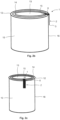
- Fig. 2b shows a three-dimensional view of a can 10 with a moving element 1.
- the can 10 is designed here as a patented lid can.
- the patented lid can is a suitable metal packaging for chemical products, e.g., paints and varnishes, which is also stackable.
- a removable and movable can lid 12 is located on the can 10.
- the can 10 and the can lid 12 are preferably made of tinplate.
- the body of the can 10 is cylindrical.
- the can lid 12 is circular and has a fixed movement element 1 on the top 13.
- the movement element 1 is attached to the lid edge 14, which does not extend all the way to one can wall 16.
- the movement element 1 extends as a handle 2 along the side can wall 16 downwards to the can bottom.
- the movement element 1 is attached to the lid edge 14 in the attachment area 15, e.g., using adhesive or glue.
- the short side 6 does not extend beyond the inner lid edge.
- the movement element 1 is soldered to the lid edge 14 in the attachment area 15. A spot weld connection between the lid edge 14 and the short side 6 of the movement element 1 is also possible. All metal joining techniques suitable for securely attaching the movement element 1 to the lid edge 14 in the attachment area 15 can be used for the attachment.
- Fig. 2c shows another can 10 with a moving element 1 in a three-dimensional view.
- the can 10 is also designed as a patented lid can.
- On the can 10 is a can lid 12 with a moving element 1 facing the viewer.
- the body of the can 10 is also cylindrical, but narrower than in Fig. 2b
- the can lid 12 is circular and has a fixed movement element 1 on the top side 13.
- the movement element 1 is attached to the lid edge 14.
- the movement element 1, attached to the lid edge 14, extends as a handle 2 along the side can wall 16 downwards toward the can bottom.
- the movement element 1 is firmly connected to the lid edge in the attachment area 15.
- the short side 6 does not extend beyond the inner lid edge.
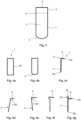
- Fig. 3 shows a moving element 1 in a non-angled state in a top view.
- the moving element 1 has a shorter side 6 and a longer side 7, which are essentially separated by a bend line 8.
- the longer side 7 forms a handle 2 or handle-like element.
- the longer side 7 has a rounded portion 3 at the end, which can minimize the risk of injury.
- the shorter side 6 ends with a substantially straight edge 5.
- the edge 5 ends with the inner wheel of the can lid. Any protrusion would pose a risk of injury.
- Fig. 4a shows a plan view of a movement element 1 in its raw state. It shows an essentially elongated rectangle 40 from which an angled handle 2 can be formed.
- the movement element 1 is produced as an elongated rectangle 40 from a sheet of sheet metal or tinplate using punching tools. Burrs are removed by light deburring. The width and thickness of the movement element 1 must be adapted to ensure good grip properties.
- Fig. 4b shows a top view of a moving element 1 after a first processing step.
- a rounded portion 3 is provided on one side to minimize the risk of injury.
- the moving element 1 is punched directly with the rounded portion 3.
- the rounded portion 3 then no longer needs to be created by machining.
- a light deburring would then be the next step before any bending or angling takes place.
- Fig. 4c shows a first embodiment of a moving element 1 in a side view.
- the moving element 1 is angled at the angled line 8 and forms a shorter side 6 with a first end 9a and a longer side 7, which is used as a handle 2.
- the shorter side 6 and the longer side 7 with a second end 9b form a substantially right angle.
- the longer side 7 has a slight curve at the second end 9b, which serves for a better grip.
- the curve points away from the can wall when the can lid is in place.
- a combination of curvature and rounding, as in Fig. 3 shown, at the second end 9b allows a safe and optimal intervention.
- Fig. 5 shows a can lid 12 with a movement element 1 according to the invention shown in cross section.
- the can lid 12 has a top side 13 and a bottom side 11.
- the can lid 12 has an edge 14.
- a movement element 1 is fastened to the edge 14 in the fastening area 15, which has a handle 2 or handle area 2.
- the can lid 12 with the movement element 1 is usually located on a can. Even after a long time, if the can has not been moved or has hardly been moved, there are usually residues of paint, varnish, putty, glue or other contents on the underside 11 of the can lid, which generally lead to contamination or soiling of the fingers or hands when the can lid 12 is opened without the handle 2.
- Fig. 7a shows a moving element 1 according to the invention with a magnetic region 70.
- the magnetic region 70 is located on the short side 6 and approximately corresponds to the fastening region 15.
- the magnetic region 70 can comprise a permanent magnet 70 which is attached or permanently fastened in the fastening region 15 of the short side 6. Since tinplate packaging is magnetic, the magnetic region 70 of the moving element 1 can be placed onto an edge 14 of a can lid 12. After the can lid 12 has been opened, it can be lifted off and moved using the handle 2 of the attached moving element 1. The force of the magnetic region 70 is crucial for how well the moving element 1 adheres to the can lid 12. A fixed connection between the can lid 12 and the moving element 1 is omitted in this embodiment. Furthermore, the moving element 1 with a magnetic region 70 can be used multiple times, even as often as desired.
- Fig. 7b shows yet another embodiment of a moving element 1 with two magnetic areas 70, 72.
- a first magnetic area 70 is located on the short side 6 and a second magnetic area 72 is located on the longer side 7. If a magnetic area 72 is located on the longer side 7, this can contribute to the stability of the moving element 1, since it then adheres better to a can wall.
- the magnetic area 72 can also be attached to the outside of the handle 2, creating a magnetic connection with other cans.
- the short side 6 should be firmly connected to the lid rim 14 to ensure basic stability.
- Fig. 8a shows a movement element 1 with handle 2 in a further embodiment with a larger magnetic region 70 in a three-dimensional representation.
- the movement element 1 has in this embodiment a longer magnetic region 70 that extends on the top side 13 of the can lid up to approximately the center of the can lid.
- the side 6, which was short in the previous exemplary embodiments, is longer here, possibly the same length as the handle or even longer. This provides a larger contact surface between the movement element 1 and the top side 13 of the can lid 12. If the movement element 1 has two similar or identical magnetic regions 70, 72 and the sides are of approximately the same length, then it does not matter which way the movement element 1 is attached. This ensures rapid availability and applicability.
- Fig. 8b shows a movement element 1 in yet another embodiment in a three-dimensional representation, wherein the movement element 1 extends completely over the can lid 12 and has two point-like magnetic areas 81, 82. The shorter side becomes the longer one here.
- Fig. 8c shows a can lid 12 with a handle 2, wherein the shorter side 6 extends with a first end 9a over an edge fastening area 90 onto the can lid top 13.
- a second end 9b on the longer side 7 of the handle 2 is free, or a free end.
- the handle 2 is fastened on the top in the edge fastening area 90 and extends inward, which guarantees an even more secure hold since the fastening surface is enlarged.
- Fig. 9b shows a movement element 1 in a further embodiment with a rounded angle in a side view.
- the angle can be adjusted to meet the respective application needs and stackability.
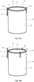
- Fig. 10a shows a can 10 with a moving element 1.
- the moving element 1 has a projection or extension 50 on the handle 2, which projects beyond the edge 14 of the top 13.
- the extension 50 also called the first stabilizer 50, serves for stabilization or improved stackability.
- a second stabilizer 52 is arranged opposite on the can wall 16, which also projects beyond the edge 14 of the top 13 to prevent cans stacked on top of one another from slipping.
- Fig. 10b shows another can 10 with a movement element 1 and two stabilizers 52, 53.
- a third stabilizer 53 is arranged at a distance in order to completely prevent slipping of cans stacked on top of each other and to ensure even better stackability.
- a can lid 12 can be easily moved, lifted, turned over, or inverted, as well as picked up and placed on a can. Contamination with the contents, such as paint, glue, putty, or varnish, can be avoided.
- the present invention is applicable to all metal packaging made of tinplate and containers that include a lid, such as push-in lid cans or patent lid cans, push-in lid buckets, patent lid buckets, ring buckets or pails, hobbocks, etc., and all volumes.
- Application examples for such metal packaging are diverse: varnishes and paints, wood preservatives, sealants, adhesives, lubricating greases, pastes, casting compounds, bitumen, resins, adhesives, printing inks, emulsion paints, greases, and chemical products.
- the present invention shows a moving element, a can lid, a can and a method for moving a can lid. It goes without saying that a person skilled in the art will be able to conceive numerous further embodiments based on the exemplary embodiments described.
Landscapes
- Engineering & Computer Science (AREA)
- Mechanical Engineering (AREA)
- Details Of Rigid Or Semi-Rigid Containers (AREA)
- Closures For Containers (AREA)
Claims (13)
- Élément de déplacement (1) au niveau d'un couvercle de boîte mobile refermable (12) comprenant :une poignée (2) sensiblement coudée qui est fixée à un premier côté (6) sur la face supérieure (13) du couvercle de boîte (12) et qui s'étend avec un second côté (7) en direction de la face inférieure du couvercle de boîte (11),caractérisé en ce que la poignée (2) présente au moins une zone magnétique (70, 72) qui se trouve au niveau du premier côté (6) et correspond à peu près à une zone de fixation (15).
- Élément de déplacement (1) selon la revendication 1, dans lequel la poignée coudée (2) présente un angle sensiblement droit (4), dans lequel un côté plus long (7) de la poignée (2) est extensible le long d'une paroi de boîte (16).
- Élément de déplacement (1) selon l'une quelconque des revendications précédentes, dans lequel la poignée coudée (2) comprend de préférence un matériau métallique.
- Élément de déplacement (1) selon l'une quelconque des revendications précédentes, dans lequel la poignée coudée (2) présente un bord (5) sensiblement droit au niveau d'une première extrémité (9a) et présente un arrondi (3) et/ou une courbure au niveau d'une seconde extrémité (9b).
- Élément de déplacement (1) selon l'une quelconque des revendications précédentes, dans lequel la poignée coudée (2) est formée ou façonnée par un rectangle (40) sensiblement allongé.
- Élément de déplacement (1) selon l'une quelconque des revendications précédentes, dans lequel un côté plus court (6) de la poignée coudée (2) se termine sensiblement vers l'intérieur au niveau du bord (14) du couvercle de boîte (12).
- Couvercle de boîte mobile (12) selon la revendication 1, dans lequel la poignée (2) est fixée sur la face supérieure (13) au niveau d'un bord (14) et se termine par le bord (14) vers l'intérieur ou s'étend sur la face supérieure (13) au-dessus du bord (14) vers l'intérieur.
- Couvercle de boîte mobile (12) selon l'une quelconque des revendications précédentes 6 et 7, dans lequel la poignée (2) au niveau du bord (14) du couvercle de boîte s'étend au-delà de la face inférieure du couvercle de boîte (11).
- Couvercle de boîte mobile (12) selon l'une des revendications précédentes 1 et 8, dans lequel la poignée (2) est fixée sur la face supérieure (13) du couvercle de boîte par un assemblage collé, un assemblage brasé, un assemblage soudé ou un assemblage riveté.
- Boîte (10) comprenant un couvercle de boîte mobile (12) selon les revendications 1 à 10.
- Boîte (10) selon la revendication 10 comprenant une zone de stabilisation (50, 52, 53).
- Procédé de déplacement d'un couvercle de boîte (12) qui comprend les étapes suivantes :la fourniture d'un couvercle de boîte (12) avec une poignée (2) sensiblement coudée selon l'une des revendications 1 à 11 ;la saisie de la poignée (2) sensiblement coudée ; etle déplacement du couvercle de boîte (12) à l'aide de la poignée (2).
- Procédé selon la revendication 12, dans lequel le déplacement du couvercle de boîte (12) au moyen de la poignée (2) comprend :
la réception d'un couvercle de boîte déposé (12) ainsi que le positionnement pour fermer le couvercle de boîte (12) sur une ouverture d'une boîte (10).
Priority Applications (1)
| Application Number | Priority Date | Filing Date | Title |
|---|---|---|---|
| HRP20251065TT HRP20251065T1 (hr) | 2020-11-23 | 2021-09-29 | Pokretni element za poklopac limenke |
Applications Claiming Priority (1)
| Application Number | Priority Date | Filing Date | Title |
|---|---|---|---|
| PCT/IB2020/061022 WO2022106873A1 (fr) | 2020-11-23 | 2020-11-23 | Élément de déplacement pour couvercle de boîte |
Publications (3)
| Publication Number | Publication Date |
|---|---|
| EP4001151A1 EP4001151A1 (fr) | 2022-05-25 |
| EP4001151B1 true EP4001151B1 (fr) | 2025-06-04 |
| EP4001151C0 EP4001151C0 (fr) | 2025-06-04 |
Family
ID=73646396
Family Applications (1)
| Application Number | Title | Priority Date | Filing Date |
|---|---|---|---|
| EP21199760.6A Active EP4001151B1 (fr) | 2020-11-23 | 2021-09-29 | Élément de déplacement pour couvercles de boîte |
Country Status (5)
| Country | Link |
|---|---|
| EP (1) | EP4001151B1 (fr) |
| ES (1) | ES3040553T3 (fr) |
| HR (1) | HRP20251065T1 (fr) |
| PL (1) | PL4001151T3 (fr) |
| WO (1) | WO2022106873A1 (fr) |
Citations (6)
| Publication number | Priority date | Publication date | Assignee | Title |
|---|---|---|---|---|
| US1725477A (en) * | 1928-06-16 | 1929-08-20 | Poulson Robert | Milk-bottle-cap lifter |
| FR1051994A (fr) * | 1952-03-03 | 1954-01-20 | Dispositif de bouchage amovible pour bouteille | |
| DE9208029U1 (de) * | 1992-06-01 | 1992-10-22 | Lin, Wen-Hsiung, Panchiao, Taipeh | Aufreißverschluß für Flaschen |
| WO2004052738A1 (fr) * | 2002-12-10 | 2004-06-24 | Enrico Folchini | Boite utilisee pour le conditionnement de produits liquides et procede de fabrication de ladite boite |
| WO2004096693A1 (fr) * | 2003-04-26 | 2004-11-11 | Young-Mun Kwak | Module d'ouverture d'une conserve integree |
| US20150069095A1 (en) * | 2009-03-03 | 2015-03-12 | Cool Gear International Llc | Cap adapted to engage container with another object |
Family Cites Families (3)
| Publication number | Priority date | Publication date | Assignee | Title |
|---|---|---|---|---|
| US3269586A (en) * | 1964-08-03 | 1966-08-30 | Terry Y Quimby | Opener and handle for a beverage container |
| CH702630A2 (de) * | 2010-02-03 | 2011-08-15 | Cosmocan Technology Ag | Dose mit einer eindrückbaren Öffnung, Verfahren und Vorrichtung zum Herstellen dieser Dose. |
| BR202014030853U2 (pt) * | 2014-12-09 | 2017-11-14 | Acacio Da Silva Edilberto | disposição construtiva introduzida em lacre para embalagem de bebidas |
-
2020
- 2020-11-23 WO PCT/IB2020/061022 patent/WO2022106873A1/fr not_active Ceased
-
2021
- 2021-09-29 PL PL21199760.6T patent/PL4001151T3/pl unknown
- 2021-09-29 EP EP21199760.6A patent/EP4001151B1/fr active Active
- 2021-09-29 ES ES21199760T patent/ES3040553T3/es active Active
- 2021-09-29 HR HRP20251065TT patent/HRP20251065T1/hr unknown
Patent Citations (6)
| Publication number | Priority date | Publication date | Assignee | Title |
|---|---|---|---|---|
| US1725477A (en) * | 1928-06-16 | 1929-08-20 | Poulson Robert | Milk-bottle-cap lifter |
| FR1051994A (fr) * | 1952-03-03 | 1954-01-20 | Dispositif de bouchage amovible pour bouteille | |
| DE9208029U1 (de) * | 1992-06-01 | 1992-10-22 | Lin, Wen-Hsiung, Panchiao, Taipeh | Aufreißverschluß für Flaschen |
| WO2004052738A1 (fr) * | 2002-12-10 | 2004-06-24 | Enrico Folchini | Boite utilisee pour le conditionnement de produits liquides et procede de fabrication de ladite boite |
| WO2004096693A1 (fr) * | 2003-04-26 | 2004-11-11 | Young-Mun Kwak | Module d'ouverture d'une conserve integree |
| US20150069095A1 (en) * | 2009-03-03 | 2015-03-12 | Cool Gear International Llc | Cap adapted to engage container with another object |
Also Published As
| Publication number | Publication date |
|---|---|
| EP4001151A1 (fr) | 2022-05-25 |
| ES3040553T3 (en) | 2025-11-03 |
| EP4001151C0 (fr) | 2025-06-04 |
| WO2022106873A1 (fr) | 2022-05-27 |
| HRP20251065T1 (hr) | 2026-04-10 |
| PL4001151T3 (pl) | 2026-02-02 |
Similar Documents
| Publication | Publication Date | Title |
|---|---|---|
| EP3385184A1 (fr) | Récipient destiné à conserver hermétiquement des produits, en particulier des produits alimentaires | |
| DE4410790A1 (de) | Schraubkappe mit Anschweißring | |
| DE60303008T2 (de) | Wiederverschliessbarer deckel für einen behälter | |
| DE6602576U (de) | Deckel fuer dosen oder behaelter mit einem aufreissstreifen | |
| EP4001151A1 (fr) | Élément de déplacement pour couvercles de boîte | |
| EP2070826B1 (fr) | Récipient doté d'un élément de fermeture à ouverture facile | |
| EP0005264B1 (fr) | Récipient | |
| DE2832706A1 (de) | Deckel aus blech fuer behaelter mit im deckelspiegel vorgesehener aufreisslinie | |
| DE1757471B2 (de) | Vollaufreissdeckel aus blech fuer leicht zu oeffnende dosen | |
| DE102008011919A1 (de) | Behältnis für Flüssigkeiten | |
| EP2546159A1 (fr) | Récipient refermable | |
| DE10028798C2 (de) | Dosenöffner für Klemmdeckeldosen | |
| DE19620448C2 (de) | Verfahren zur Herstellung eines leicht zu öffnenden Dosendeckels | |
| DE4322459A1 (de) | Farbbehälter-Restentleerung | |
| CH453117A (de) | Dosenverschluss | |
| EP2531439A1 (fr) | Boîte pourvue d'une ouverture à enfoncer, procédé et dispositif pour fabriquer cette boîte | |
| DE102023134289A1 (de) | Deckel mit einem Foliendeckel, Eimer und Gebinde | |
| DE9311330U1 (de) | Behälter | |
| DE102023110083A1 (de) | Mehrwegverpackung | |
| DE20120761U1 (de) | Aufnahme von Kleinteilen | |
| DE102006046664B4 (de) | Packung mit peelfähigem Deckel | |
| EP1082184A2 (fr) | Zone superficielle legerement inclinee dans un couvercle de fermeture en tole | |
| DE10359592A1 (de) | Kunststoff-Behälter mit Öffnungsvorrichtung aus Metall | |
| DE3543954A1 (de) | Verpackungs- und tragkarton fuer eine mehrzahl von behaeltern, insbesondere flaschen, sowie hilfswerkzeug zur herstellung solcher kartons | |
| DE102010032327A1 (de) | Verstärkter Behälterdeckel |
Legal Events
| Date | Code | Title | Description |
|---|---|---|---|
| REG | Reference to a national code |
Ref country code: HR Ref legal event code: TUEP Ref document number: P20251065T Country of ref document: HR |
|
| PUAI | Public reference made under article 153(3) epc to a published international application that has entered the european phase |
Free format text: ORIGINAL CODE: 0009012 |
|
| STAA | Information on the status of an ep patent application or granted ep patent |
Free format text: STATUS: THE APPLICATION HAS BEEN PUBLISHED |
|
| AK | Designated contracting states |
Kind code of ref document: A1 Designated state(s): AL AT BE BG CH CY CZ DE DK EE ES FI FR GB GR HR HU IE IS IT LI LT LU LV MC MK MT NL NO PL PT RO RS SE SI SK SM TR |
|
| STAA | Information on the status of an ep patent application or granted ep patent |
Free format text: STATUS: REQUEST FOR EXAMINATION WAS MADE |
|
| 17P | Request for examination filed |
Effective date: 20221117 |
|
| RBV | Designated contracting states (corrected) |
Designated state(s): AL AT BE BG CH CY CZ DE DK EE ES FI FR GB GR HR HU IE IS IT LI LT LU LV MC MK MT NL NO PL PT RO RS SE SI SK SM TR |
|
| STAA | Information on the status of an ep patent application or granted ep patent |
Free format text: STATUS: EXAMINATION IS IN PROGRESS |
|
| 17Q | First examination report despatched |
Effective date: 20230216 |
|
| GRAP | Despatch of communication of intention to grant a patent |
Free format text: ORIGINAL CODE: EPIDOSNIGR1 |
|
| STAA | Information on the status of an ep patent application or granted ep patent |
Free format text: STATUS: GRANT OF PATENT IS INTENDED |
|
| INTG | Intention to grant announced |
Effective date: 20241204 |
|
| GRAS | Grant fee paid |
Free format text: ORIGINAL CODE: EPIDOSNIGR3 |
|
| RAP1 | Party data changed (applicant data changed or rights of an application transferred) |
Owner name: RUEEGGER, ROBIN STEPHAN Owner name: JAIJI, FERDI Owner name: MIMMO, ROMEO |
|
| RIN1 | Information on inventor provided before grant (corrected) |
Inventor name: ROMEO, MIMMO |
|
| GRAA | (expected) grant |
Free format text: ORIGINAL CODE: 0009210 |
|
| STAA | Information on the status of an ep patent application or granted ep patent |
Free format text: STATUS: THE PATENT HAS BEEN GRANTED |
|
| RIN1 | Information on inventor provided before grant (corrected) |
Inventor name: ROMEO, MIMMO Inventor name: RUEEGGER, ROBIN STEPHAN Inventor name: JAIJI, FERDI |
|
| RAP3 | Party data changed (applicant data changed or rights of an application transferred) |
Owner name: RUEEGGER, ROBIN STEPHAN Owner name: JAIJI, FERDI Owner name: ROMEO, MIMMO |
|
| AK | Designated contracting states |
Kind code of ref document: B1 Designated state(s): AL AT BE BG CH CY CZ DE DK EE ES FI FR GB GR HR HU IE IS IT LI LT LU LV MC MK MT NL NO PL PT RO RS SE SI SK SM TR |
|
| REG | Reference to a national code |
Ref country code: GB Ref legal event code: FG4D Free format text: NOT ENGLISH |
|
| RIN1 | Information on inventor provided before grant (corrected) |
Inventor name: RUEEGGER, ROBIN STEPHAN Inventor name: JAIJI, FERDI Inventor name: ROMEO, MIMMO |
|
| REG | Reference to a national code |
Ref country code: CH Ref legal event code: EP |
|
| REG | Reference to a national code |
Ref country code: IE Ref legal event code: FG4D Free format text: LANGUAGE OF EP DOCUMENT: GERMAN |
|
| REG | Reference to a national code |
Ref country code: DE Ref legal event code: R096 Ref document number: 502021007641 Country of ref document: DE |
|
| U01 | Request for unitary effect filed |
Effective date: 20250702 |
|
| U07 | Unitary effect registered |
Designated state(s): AT BE BG DE DK EE FI FR IT LT LU LV MT NL PT RO SE SI Effective date: 20250716 |
|
| REG | Reference to a national code |
Ref country code: CH Ref legal event code: U11 Free format text: ST27 STATUS EVENT CODE: U-0-0-U10-U11 (AS PROVIDED BY THE NATIONAL OFFICE) Effective date: 20251001 |
|
| PG25 | Lapsed in a contracting state [announced via postgrant information from national office to epo] |
Ref country code: NO Free format text: LAPSE BECAUSE OF FAILURE TO SUBMIT A TRANSLATION OF THE DESCRIPTION OR TO PAY THE FEE WITHIN THE PRESCRIBED TIME-LIMIT Effective date: 20250904 Ref country code: GR Free format text: LAPSE BECAUSE OF FAILURE TO SUBMIT A TRANSLATION OF THE DESCRIPTION OR TO PAY THE FEE WITHIN THE PRESCRIBED TIME-LIMIT Effective date: 20250905 |
|
| PGFP | Annual fee paid to national office [announced via postgrant information from national office to epo] |
Ref country code: MC Payment date: 20250923 Year of fee payment: 5 |
|
| PGFP | Annual fee paid to national office [announced via postgrant information from national office to epo] |
Ref country code: TR Payment date: 20250923 Year of fee payment: 5 |
|
| PGFP | Annual fee paid to national office [announced via postgrant information from national office to epo] |
Ref country code: GB Payment date: 20250919 Year of fee payment: 5 |
|
| PGFP | Annual fee paid to national office [announced via postgrant information from national office to epo] |
Ref country code: HR Payment date: 20250919 Year of fee payment: 5 |
|
| PG25 | Lapsed in a contracting state [announced via postgrant information from national office to epo] |
Ref country code: RS Free format text: LAPSE BECAUSE OF FAILURE TO SUBMIT A TRANSLATION OF THE DESCRIPTION OR TO PAY THE FEE WITHIN THE PRESCRIBED TIME-LIMIT Effective date: 20250904 |
|
| PGFP | Annual fee paid to national office [announced via postgrant information from national office to epo] |
Ref country code: IE Payment date: 20250918 Year of fee payment: 5 |
|
| REG | Reference to a national code |
Ref country code: HR Ref legal event code: ODRP Ref document number: P20251065T Country of ref document: HR Payment date: 20250919 Year of fee payment: 5 |
|
| U20 | Renewal fee for the european patent with unitary effect paid |
Year of fee payment: 5 Effective date: 20250924 |
|
| REG | Reference to a national code |
Ref country code: ES Ref legal event code: FG2A Ref document number: 3040553 Country of ref document: ES Kind code of ref document: T3 Effective date: 20251103 |
|
| PG25 | Lapsed in a contracting state [announced via postgrant information from national office to epo] |
Ref country code: IS Free format text: LAPSE BECAUSE OF FAILURE TO SUBMIT A TRANSLATION OF THE DESCRIPTION OR TO PAY THE FEE WITHIN THE PRESCRIBED TIME-LIMIT Effective date: 20251004 |
|
| PG25 | Lapsed in a contracting state [announced via postgrant information from national office to epo] |
Ref country code: SM Free format text: LAPSE BECAUSE OF FAILURE TO SUBMIT A TRANSLATION OF THE DESCRIPTION OR TO PAY THE FEE WITHIN THE PRESCRIBED TIME-LIMIT Effective date: 20250604 |
|
| PGFP | Annual fee paid to national office [announced via postgrant information from national office to epo] |
Ref country code: CH Payment date: 20251001 Year of fee payment: 5 |
|
| PG25 | Lapsed in a contracting state [announced via postgrant information from national office to epo] |
Ref country code: CZ Free format text: LAPSE BECAUSE OF FAILURE TO SUBMIT A TRANSLATION OF THE DESCRIPTION OR TO PAY THE FEE WITHIN THE PRESCRIBED TIME-LIMIT Effective date: 20250604 |
|
| PG25 | Lapsed in a contracting state [announced via postgrant information from national office to epo] |
Ref country code: SK Free format text: LAPSE BECAUSE OF FAILURE TO SUBMIT A TRANSLATION OF THE DESCRIPTION OR TO PAY THE FEE WITHIN THE PRESCRIBED TIME-LIMIT Effective date: 20250604 |
|
| PGFP | Annual fee paid to national office [announced via postgrant information from national office to epo] |
Ref country code: ES Payment date: 20251030 Year of fee payment: 5 |
|
| PGFP | Annual fee paid to national office [announced via postgrant information from national office to epo] |
Ref country code: HU Payment date: 20250923 Year of fee payment: 5 |
|
| PLBE | No opposition filed within time limit |
Free format text: ORIGINAL CODE: 0009261 |
|
| REG | Reference to a national code |
Ref country code: HR Ref legal event code: T1PR Ref document number: P20251065 Country of ref document: HR |
|
| STAA | Information on the status of an ep patent application or granted ep patent |
Free format text: STATUS: NO OPPOSITION FILED WITHIN TIME LIMIT |
|
| REG | Reference to a national code |
Ref country code: CH Ref legal event code: L10 Free format text: ST27 STATUS EVENT CODE: U-0-0-L10-L00 (AS PROVIDED BY THE NATIONAL OFFICE) Effective date: 20260416 |
|
| PGFP | Annual fee paid to national office [announced via postgrant information from national office to epo] |
Ref country code: PL Payment date: 20250911 Year of fee payment: 5 |
|
| 26N | No opposition filed |
Effective date: 20260305 |