EP4001168B1 - Dispositif d'arrimage vertical et horizontal de charges empilées et son utilisation - Google Patents
Dispositif d'arrimage vertical et horizontal de charges empilées et son utilisation Download PDFInfo
- Publication number
- EP4001168B1 EP4001168B1 EP21207915.6A EP21207915A EP4001168B1 EP 4001168 B1 EP4001168 B1 EP 4001168B1 EP 21207915 A EP21207915 A EP 21207915A EP 4001168 B1 EP4001168 B1 EP 4001168B1
- Authority
- EP
- European Patent Office
- Prior art keywords
- shaft
- housing
- longitudinal direction
- locking body
- break
- Prior art date
- Legal status (The legal status is an assumption and is not a legal conclusion. Google has not performed a legal analysis and makes no representation as to the accuracy of the status listed.)
- Active
Links
Images


Classifications
-
- B—PERFORMING OPERATIONS; TRANSPORTING
- B65—CONVEYING; PACKING; STORING; HANDLING THIN OR FILAMENTARY MATERIAL
- B65D—CONTAINERS FOR STORAGE OR TRANSPORT OF ARTICLES OR MATERIALS, e.g. BAGS, BARRELS, BOTTLES, BOXES, CANS, CARTONS, CRATES, DRUMS, JARS, TANKS, HOPPERS, FORWARDING CONTAINERS; ACCESSORIES, CLOSURES, OR FITTINGS THEREFOR; PACKAGING ELEMENTS; PACKAGES
- B65D90/00—Component parts, details or accessories for large containers
- B65D90/0006—Coupling devices between containers, e.g. ISO-containers
- B65D90/0013—Twist lock
Definitions
- the invention relates to a device for vertical and horizontal load securing of stacked cargo.
- the invention also relates to a use for vertical and horizontal load securing of modular break-bulk cargo.
- Twistlocks are devices that are often used to secure shipping containers that comply with ISO (International Standards Organisation) regulations. Such twistlocks are very frequently used in shipping, where the twistlocks interlock between corner fittings of two stacked containers on a container ship, or where twistlocks are fixedly mounted on a deck of a container ship to anchor a container to the deck. There are also other applications for twistlocks, for example when transporting containers by rail or truck.
- Twistlocks have traditionally been in the form of a housing, through which a shaft protrudes, with a cone formed or attached to either side of the shaft.
- the cones are slightly elongated to fit through an elongate slot in the corner fitting of a container and to lock when rotated in the corner fitting to a position transverse to the slot.
- both cones are locked in a corner fitting, two containers located one above the other are fastened together.
- twistlock is known, inter alia, from US 5 632 586 .
- US '586 describes a twistlock in which a single cone operates automatically so that vertical forces on the twistlock cone can be used both to lock a container in place and to unlock the container.
- Other twistlocks are known from GB 2 476 102 A and WO 2017/141005A1 .
- twistlock is not suitable for horizontal and vertical securing of stacked cargo.
- the twistlock can only secure a container vertically on a ship's deck or to an underlying container. There is no horizontal securing of any kind between adjacent containers. With containers stacked above decks on a container ship, it is possible that a high stack, despite containers being vertically attached to each other, topple over during rough weather and fall into the sea. As a result, the height of the stack of containers is limited.
- a modular break-bulk load comprises large general cargo, such as the blades of a windmill, which are placed above deck on a ship.
- a module of a modular break-bulk load comprises metal frames attached to the general cargo item near ends or a metal frame that delimits the entire general cargo item in three dimensions.
- the metal frames comprise corner fittings as known in shipping containers that comply with ISO regulations.
- the metal frames are stacked on top of each other and secured with twistlocks according to the prior art. Again, the frames are only secured in a vertical direction, which means that there is a real risk of a stacked modular break-bulk load tipping over.
- the stacks are additionally secured using chains from a deck to containers or modules of the modular break-bulk load. This requires extra material and additional actions, which makes securing the load time-consuming.
- the present invention aims to solve at least some of the above problems or drawbacks.
- the present invention relates to a device according to claim 1.
- the great advantage of this device is that in addition to a first shaft, comprising locking bodies at its ends, it also comprises a second parallel shaft.
- the second shaft also comprises locking bodies at its ends.
- the locking bodies are elongated to fit through an elongate slot in the corner fitting of a container or a frame of a module of a modular break-bulk load.
- the locking bodies lock in a position transverse to the slot.
- containers or modules of a modular break-bulk load are secured to each other or to the deck of a ship in a vertical direction.
- the device comprises two shafts, the device can be used not only to secure containers or modules of a modular break-bulk load of a first stack in a vertical direction, but also to secure containers or modules of a modular break-bulk load of a second adjacent stack in a vertical direction. Because both shafts are comprised in the same housing, the containers or modules of two adjacent stacks are automatically also secured horizontally by the housing. As a result, instead of several separate stacks, a single stack with a wide base is obtained, whereby the risk of tipping is small. Due to the device, it is not necessary to use additional chains or elements and stacked cargo can be secured both vertically and horizontally with the same number of operations as with vertical only securing.
- the present invention relates to a use according to claim 12.
- This use results in an advantageous securing of stacked modular break-bulk cargo, wherein modules of a modular break-bulk load are secured not only in the vertical direction to underlying modules or to a deck of a ship, but also in a horizontal direction to modules of adjacent stacks of modular break-bulk cargo.
- modules of a modular break-bulk load are secured not only in the vertical direction to underlying modules or to a deck of a ship, but also in a horizontal direction to modules of adjacent stacks of modular break-bulk cargo.
- a single stack with a wide base is obtained, whereby the risk of tipping is small.
- it is not necessary to use additional chains or elements and stacked modular break-bulk cargo can be secured both vertically and horizontally with the same number of operations as with vertical only securing.
- a segment means one or more segments.
- Quoting numerical intervals by endpoints comprises all integers, fractions and/or real numbers between the endpoints, these endpoints included.
- break-bulk or general cargo are goods whose quantity is not specified by size or weight, but per piece.
- a modular break-bulk load is a load of general cargo in which an item of general cargo is packaged to form a module, so that several modules of the general cargo can be stacked on top of each other.
- Non-limiting examples of this are boxes, crates, barrels or bales.
- an item of general cargo comprises near its ends a preferably metal frame attached to the general cargo item, or the general cargo item is delimited in three dimensions by a preferably metal frame, the preferably metal frames being configured for stacking on top of one another.
- a break-bulk vessel is a vessel suitable for carrying break-bulk in a cargo hold or on deck.
- a break-bulk vessel includes cranes, which enable the vessel to load or unload break-bulk independently.
- cargo is a general term for a load that is carried by means of a ship, such as, for example, containers or modular break-bulk cargo.
- a spherical cap is a part of a sphere that is cut off from the sphere by a plane.
- a cylindrical segment is a portion of a cylinder cut off from the cylinder by a plane parallel to a longitudinal axis of the cylinder.
- the invention relates to a device for vertical and horizontal load securing of stacked cargo.
- the device comprises a housing, a first shaft and a second shaft.
- the housing is preferably formed from metal, more preferably from steel.
- Steel is a suitable material for absorbing tensile and compressive forces, bending forces and shear forces. These forces are considerable in the case of stacked cargo, such as containers and modules of modular break-bulk cargo, due to movements of a ship, such as a container ship or a break-bulk vessel. The movements of the ship are caused by waves at sea and can become very large in severe weather conditions. Due to the strength of steel and because steel can also deform elastically, the housing will not crack or break under the influence of tensile and compressive forces, bending forces and shear forces, even in severe weather conditions, so that a stacked cargo remains secured in vertical and horizontal directions.
- the housing preferably comprises one or more castings. Castings can be obtained quickly and easily by pouring molten metal into a mold. After cooling, a casting requires a limited number of processing steps to finish the casting.
- the first shaft comprises a longitudinal axis.
- the first shaft is rotatably borne in the housing.
- the first shaft is rotatable about its longitudinal axis.
- a first end of the first shaft projects from the housing on a first side of the housing.
- a second end of the first shaft projects from the housing on a second side of the housing.
- the second side of the housing faces the first side of the housing.
- the first end of the first shaft comprises a locking body which is radially elongated with respect to the first shaft.
- the second end of the first shaft comprises a locking body which is radially elongated with respect to the first shaft.
- "Radially elongated" means that a locking body is extended in a longitudinal direction, the longitudinal direction being transverse to the first shaft.
- the second shaft comprises a longitudinal axis.
- the second shaft is rotatably borne in the housing.
- the second shaft is rotatable about its longitudinal axis.
- a first end of the second shaft projects from the housing on the first side of the housing.
- a second end of the second shaft projects from the housing on the second side of the housing.
- the first end of the second shaft comprises a locking body which is radially elongated with respect to the second shaft.
- the second end of the second shaft comprises a locking body which is radially elongated with respect to the second shaft.
- "Radially elongated" means that a locking body is extended in a longitudinal direction, the longitudinal direction being transverse to the second shaft.
- the second shaft is parallel to the first shaft.
- the shafts are preferably made of metal, more preferably steel.
- the shafts are preferably stamped from a block of hot metal. This is advantageous because it avoids having an imperfection in a shaft, such as a casting flaw or a void, which has a negative influence on the tensile strength of the shafts.
- a radially elongated locking body is preferably configured to be received through an elongate slot in a corner fitting of a container.
- the container is preferably in accordance with standard ISO 668:2020. Said standard defines dimensions for the corner fitting and the elongate slot.
- a radially elongated locking body is a separate part that is fixedly mounted on a shaft or formed as a single piece together with the shaft.
- a shaft and its locking bodies are a single piece.
- a shaft and its locking bodies are made of metal, more preferably of steel.
- a shaft and its locking bodies are stamped from a single block of hot metal.
- a locking body at one end of the shaft twists into the corner fitting of a container or module of a modular break-bulk load, preventing a locking body from moving through the elongate slot of the corner fitting and the device is attached to the corner fitting of the container or module of a modular break-bulk load.
- the locking bodies at the first and second ends of a shaft are configured to simultaneously secure the device to two stacked containers or modules of a modular break-bulk cargo by rotation of the shaft.
- containers or modules of a modular break-bulk load are secured to each other or to the deck of a ship in a vertical direction.
- the distance between the two shafts is preferably greater than a maximum length of a locking body.
- the device can be used not only to secure containers or modules of a modular break-bulk load of a first stack in a vertical direction, but also to secure containers or modules of a modular break-bulk load of a second adjacent stack in a vertical direction. Because both shafts are comprised in the same housing, the containers or modules of two adjacent stacks are automatically also secured to each other in a horizontal direction by the housing. As a result, instead of several separate stacks, a single stack with a wide base is obtained, whereby the risk of tipping is small. Due to the device, it is not necessary to use additional chains or elements to secure stacked cargo and stacked cargo can be secured both vertically and horizontally with the same number of operations as with vertical only securing.
- locking bodies of a shaft are symmetrical with respect to the longitudinal axis of the shaft. This is advantageous because it prevents the device from being misoriented when a locking body is facing the elongate slot in a corner fitting of a container or module of a modular break-bulk load.
- the first and second shaft are identical. This is advantageous when assembling the device, because the first and the second shaft may be interchanged. This is also advantageous because when placing the device, both the first axis or the second axis may be directed towards the elongate slot in a corner fitting of a container or module of a modular break-bulk load.
- the housing is formed from steel having a tensile strength of at least 390 MPa, preferably at least 400 MPa, more preferably at least 410 MPa, even more preferably at least 420 MPa and even more preferably at least 500 MPa.
- Steel with a tensile strength of at least 390 MPa is required to absorb tensile and compressive forces, bending forces and shear forces on the device due to ship movements.
- a shaft comprises a handle.
- the handle is positioned transversely to the shaft and projects through the housing.
- the housing comprises a slot suitable for moving the handle.
- the handle is configured to rotate the shaft about its longitudinal axis from a first to a second position over an angle ⁇ .
- a handle is a separate part that is fixed on a shaft.
- a handle is made of metal, more preferably of steel.
- the handle is preferably welded to the shaft.
- the handle is screwed into an internal thread in the shaft.
- a handle is advantageous for rotating a shaft for locking or unlocking a locking body in the elongate slot of a corner fitting of a container or module of a modular break-bulk cargo.
- a locking body is unlocked in the first position, wherein the locking body can go in and out of the corner fitting and locked in the second position.
- the handle does not require any tools to rotate the shaft.
- the handle is also an advantageous visual indication of whether or not a locking body is locked in a corner fitting.
- the angle ⁇ is at least 75° and at most 105°, preferably at least 85° and at most 95°, more preferably 90°.
- An angle ⁇ within the specified range guarantees that a locking body, after turning the handle from the first to the second position, is sufficiently transverse to the elongate slot of a corner fitting of a container or module of a modular break-bulk cargo.
- the distance between the first and the second axes is at least 100 mm and at most 400 mm, preferably at least 150 mm and at most 300 mm.
- this range it is possible to horizontally secure adjacent stacks of stacked cargo. A smaller distance results in locking bodies that are too small, as a result of which these locking bodies cannot adequately absorb the tensile and compressive forces, shear forces and bending forces. A greater distance creates excessive shear forces and bending forces on the device. In addition, this also ensures that adjacent stacks of stacked cargo are stacked horizontally further apart, so that space in a hold or on a deck of a ship is used less efficiently.
- the device comprises a spring-actuated clamping mechanism.
- the spring-actuated clamping mechanism is configured to clamp a shaft in the first and second positions.
- the first and second positions of the shaft are as in a previously described embodiment.
- the spring-actuated clamping mechanism is advantageous to prevent a shaft from rotating inadvertently out of the first or second position due to, for example, vibrations, and a locking body from being locked or unlocked inadvertently.
- the spring-actuated clamping mechanism comprises a clamping body which is tensioned against the shaft by a spring.
- the shaft comprises recesses in which the clamping body is pressed by the spring with the shaft in the first or second position.
- the recesses preferably comprise inclined or rounded side walls. This is advantageous to move the clamping body out of the recess against the spring force by exerting a torque on the shaft, so that the shaft is no longer clamped in the first or second position and can be moved to another position.
- a non-limiting example of a spring-actuated clamping mechanism comprises a spring and a ball.
- the spring is placed in the housing and presses the ball into a recess in a shaft, the recess being a recess in the form of a spherical cap or a cylindrical segment.
- a shaft comprises a handle.
- the handle is suitable as a lever for overcoming the spring force of the spring-actuated clamping mechanism, whereby a high spring force can be used to prevent a shaft from moving unintentionally out of the first or second position, for example due to vibrations, while the spring-actuated clamping mechanism can be overcome by muscular force.
- the spring-actuated clamping mechanism is configured to clamp a shaft in a third position.
- the third position is located between the first and the second position.
- a third position is advantageous to provide, for example, a third operating condition of the device.
- a first operating condition is that both locking bodies of a shaft are unlocked, as with a shaft in the first position.
- a second operating condition is that both locking bodies of a shaft are locked, as with a shaft in the second position.
- the third operating condition is that one of the two locking bodies of a shaft is partially locked, and the other locking body is unlocked.
- Partially locked means that a locking body is not substantially transverse to the elongate slot of a corner fitting, nor is it aligned with the elongate slot.
- the device is already attached to said corner fitting but cannot yet absorb tensile forces in the longitudinal direction of the shaft.
- This third operating condition is advantageous for provisionally fixing a device to a corner fitting of for instance a first container or module of a modular break-bulk load, after which a second container or module is placed on top of the first container or module. If the second container or module taps against the device instead of being placed on the device, the device will remain in place. This avoids having to place a device on the first container several times before the device can be attached to the second container.
- the shaft can be moved to the second position, whereby the device is secured to the first and second containers and the first and second containers are secured vertically.
- the locking bodies at the first end and the second end of a shaft each have their own longitudinal direction.
- the longitudinal direction is perpendicular to the shaft.
- the angle between the longitudinal direction of the locking body at the first end and the longitudinal direction of the locking body at the second end is at least 15° and at most 30°, preferably at least 20° and at most 25°, more preferably 22.5°.
- the longitudinal direction of either locking body is substantially parallel to an elongate slot of a corner fitting of a container or module of a modular break-bulk cargo, allowing said locking body to be moved in and out of the elongate slot of the corner fitting.
- the longitudinal direction of the other locking body forms an angle with the elongate slot which is equal to the angle between the longitudinal directions of the two locking bodies.
- a locking body By careful determination of a width of a locking body, where the width of a locking body is smaller than the width of the elongate slot, a locking body can also still be moved in and out of the elongate slot of the corner fitting if a locking body is at an angle to the elongate slot which falls within the above defined range for an angle between the longitudinal directions of the locking bodies. Due to the angle between the longitudinal directions of the two locking bodies, the other locking body can therefore also be moved in and out of the elongate slot.
- the locking body which in the first position was substantially parallel to the elongate slot of a corner fitting will now form an angle ⁇ with the elongate slot, while the other locking body will form an angle with the elongate slot equal to angle ⁇ plus the angle between the longitudinal directions of the two locking bodies or equal to angle ⁇ minus the angle between the longitudinal directions of the two locking bodies.
- angle ⁇ By careful choice of the angle ⁇ , it can be ensured that one of the two locking bodies, after the rotation of the shaft through the angle ⁇ , forms an angle with the elongate slot, which falls within the above defined range for an angle between the longitudinal directions of the locking bodies, while the other locking body has an angle which is greater and outside the defined range.
- the housing comprises an elongate body having a longitudinal direction, transverse direction and height direction.
- the longitudinal direction is along a perpendicular connecting line between the first and second shafts.
- the height direction is parallel to the first and second shafts.
- the transverse direction is perpendicular to the longitudinal direction and the height direction.
- the elongate body is flat on the first and second sides of the housing and located along the height direction between the locking body at the first and second ends of the first and second shafts.
- the elongate body is advantageous for horizontally securing containers or modules of a modular break-bulk cargo of two adjacent stacks.
- the elongate body is a suitable bridging distance between two adjacent stacks.
- the elongate body is additionally advantageous for supporting containers or modules of a modular break-bulk cargo on the flat first or second side of the elongate body and for supporting the device with the flat first or second side of the elongate body on an underlying container or module of a modular break-bulk cargo.
- the elongated body also provides a visible spacing between stacked containers or modules, allowing a freight handler to easily visually check whether stacked cargo is secured horizontally and vertically using the device.
- the elongate body has a height of at least 50 mm.
- a height of at least 50 mm is sufficient for a visible spacing between stacked containers or modules of a modular break-bulk cargo.
- a height of at least 50 mm also provides sufficient strength in the elongate body of the device.
- the elongate body has a height of at least 55 mm, more preferably at least 60 mm.
- the device can withstand a compressive force of at least 600 kN along the longitudinal direction of the elongate body.
- the device can withstand a shear force of at least 250 kN transverse to the longitudinal direction of the elongate body and parallel to the flat part of the elongate body on the first or second side of the housing.
- the device can withstand a shear force of at least 380 kN transverse to the longitudinal direction of the elongate body and perpendicular to the flat part of the elongate body on the first or second side of the housing.
- the device can withstand a bending moment about an axis, transverse to the longitudinal direction of the elongate body and parallel to the flat part of the elongate body on the first or second side of the housing, of at least 1.5 kNm. As a result, the device is sufficiently strong for the reliable securing of stacked cargo in horizontal and vertical direction, without the device breaking.
- the elongate body comprises two detachable end pieces and a middle part.
- the two detachable end pieces are attached to the middle part by means of bolts and preferably also nuts.
- the first shaft is positioned in a first detachable end piece or on a boundary between the first detachable end piece and the middle piece.
- the second shaft is positioned in a second detachable end piece or on a boundary between the second detachable end piece and the middle piece.
- the middle part is mounted on a mounting surface of a first end piece.
- the mounting surface of the first end piece is flat.
- the longitudinal axis of the first shaft is in the plane of the mounting surface of the first end piece.
- the middle part is mounted on a mounting surface of a second end piece.
- the mounting surface of the second end piece is flat.
- the longitudinal axis of the second shaft is in the plane of the mounting surface of the second end piece.
- the first and second mounting surfaces are parallel.
- the resulting twistlock can be used for vertically securing containers or modules of a modular break-bulk cargo on a side where there is no adjacent stack of containers or modules.
- the twistlock obtained automatically has a height that corresponds to the height of devices used for vertically and horizontally securing said container or module to an adjacent stack of containers or modules, so that adjacent containers or modules are aligned horizontally and there are no moments of force in the contiguous stacks of containers or modules.
- the mounting surface of the first end piece is detachably mounted on the mounting surface of the second end piece by means of bolts and preferably also nuts.
- bolts and preferably also nuts are the same bolts and nuts as for releasably mounting an end piece to the middle part, as in a previously described embodiment, so that bolts and nuts can be reused when converting a device to a single shaft twistlock and vice versa.
- the locking body at the first end of a shaft has a longitudinal direction, wherein a central cross-section along the longitudinal direction of the locking body is conical.
- the locking body at the second end of a shaft has a longitudinal direction, wherein a central cross-section along the longitudinal direction of the locking element is a segment of a circle.
- a segment of a circle has a similar advantage as in a previously described embodiment in which the central cross-section is conical.
- a segment of a circle is flatter in the horizontal direction than a cone shape near the shaft in which the locking element is comprised, so that with deviations larger than 3 cm in position between containers or modules of a modular break-bulk load to be stacked on top of each other, there is no longer necessarily an automatic alignment.
- a segment of a circle is also advantageous because for the same length of a locking body it can result in a smaller volume of the locking body, resulting in a weight saving.
- the locking bodies at the first end and the second end of a shaft are identical.
- the locking bodies may have a central cross-section which is conical or a segment of a circle, as in previously described embodiments, or another suitable shape.
- the housing comprises a beam-shaped collar near the first end and the second end of the first and the second shaft.
- the beam-shaped collar extends in a direction transverse to the perpendicular connecting line between the first and second shafts and transverse to the longitudinal direction of the first and second shafts.
- the beam-shaped collars are situated around the shafts.
- the beam-shaped collars are advantageous for absorbing shear forces from a container or module of a modular load. When sliding horizontally, a corner fitting of the container or module rests against the beam-shaped collar, so that forces are not transferred to the shaft but via the beam-shaped collar directly to the housing of the body. This prevents shafts from breaking due to shear forces.
- the housing comprises a recess at ends in the direction of a connecting line between the first and the second shaft.
- This recess is advantageous for weight saving. Because the recess is positioned at an end of the housing, this has no adverse effect on the strength of a device according to the present invention or on manufacture in case the housing is a casting.
- the invention relates to the use of a device according to the first aspect for vertical and horizontal load securing of modular break-bulk cargo.
- Modular break-bulk cargo such as but not limited to windmill components and modular housing units, are often divided into modules and stacked on top of each other.
- a module of a modular break-bulk load comprises a preferably metal frame which is secured to items of general cargo of the module, or which delimits the general cargo items in three dimensions, the preferably metal frames being configured for stacking on top of one another.
- the metal frames comprise corner fittings, analogous to the corner fittings of containers in accordance with standard ISO 668:2020.
- a device results in an advantageous securing of stacked modular break-bulk cargo, wherein modules of a modular break-bulk load are secured not only in the vertical direction to underlying modules or to a deck of a ship, but also in a horizontal direction to modules of adjacent stacks of modular break-bulk cargo.
- modules of a modular break-bulk load are secured not only in the vertical direction to underlying modules or to a deck of a ship, but also in a horizontal direction to modules of adjacent stacks of modular break-bulk cargo.
- Figure 1 shows an exploded view of a device according to an embodiment of the present invention.
- the device includes a housing and a first and second shaft (18).
- the housing comprises an elongate body.
- the elongate body comprises two end parts (10) which are releasably fastened to a middle part (13) by means of bolts (15) and nuts (14).
- the middle part is mounted on a mounting surface (22) of the end pieces (10).
- the mounting surface (22) is flat.
- the longitudinal axis of a shaft (18) is in the plane of a mounting surface (22) of an end piece (10).
- the shafts (18) extend at a first end through a first side and at a second end through an opposite second side of the housing.
- the shafts (18) comprise a locking body (17) at the first end, wherein a central cross-section in the longitudinal direction of the locking body (17) is conical.
- the shafts (18) comprise a locking body (19) at the second end, wherein a central cross-section in the longitudinal direction of the locking body (19) is a segment of a circle.
- the shafts (18) comprise a handle (20), the handle (20) being positioned transversely of the shafts (18) and extending through the housing, and the housing comprising a slot (23), suitable for moving the handle (20) from a first to a second position.
- the device includes a spring-actuated clamping mechanism configured to clamp a shaft (18) in a first, second and intermediate third position.
- the spring-actuated clamping device comprises springs (11) and balls (12).
- a shaft (18) comprises recesses (21) in the form of a spherical cap or a cylindrical segment.
- the spring (11) presses the ball (12) into a recess (21), thereby clamping a shaft (18) in the first, second or intermediate third position.
- the housing comprises a beam-shaped collar (16).
- the beam-shaped collar (16) extends in a direction transverse to the perpendicular connecting line between the shafts (18) and transverse to the longitudinal direction of the shafts (18).
- Figure 2 shows an exploded view of an alternative use of a device according to an embodiment of the present invention.
- the device is analogous to the device of Figure 1 .
- the end pieces (10) are detached from the middle part (13), after which the end pieces (10) are mounted around a single shaft (18).
- a single axis twistlock (18) is obtained from the device.
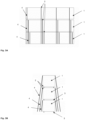
- Figure 3A and Figure 3B show a schematic representation of prior art modular break-bulk load securing.
- Figure 3A shows the break-bulk load in a direction transverse to the longitudinal direction of a break-bulk vessel.
- Figure 3B shows the break-bulk load in the longitudinal direction of a break-bulk vessel.
- the modular break-bulk load consists of modules (1) stacked three high. All modules (1) are equal.
- Each module (1) comprises a metal frame.
- a metal frame comprises attachment points (2) at the bottom and top edges.
- Stacked modules (1) are attached to each other by means of twistlocks (3).
- the module (1) at the bottom is secured to the deck of a break-bulk ship with twistlocks (3).
- the twistlocks (3) are known from the prior art.
- four sets of chains (4), withstanding a maximum load of 10 tons, are fastened to prevent modules (1) from tipping over due to wave movements.
- Figure 4 shows a schematic representation of modular break-bulk load securing using a device according to an embodiment of the present invention.
- Figure 4 shows the break-bulk load in the longitudinal direction of a break-bulk vessel.
- the modular break-bulk load consists of the same modules (1) as in Figures 3A and 3B .
- the modules (1) are stacked in adjacent substantially vertical stacks (5).
- Each module (1) of each substantially vertical stack (5) is horizontally secured in a direction transverse to the longitudinal direction of a break-bulk ship by means of devices (6) according to the present invention to a module (1) at the same height of an adjacent substantially vertical stack (5).
- the devices (6) also vertically secure each module (1) of a substantially vertical stack (5) under which another module (1) is positioned, to the module (1) below.
- Modules (1) at the bottom of the substantially vertical stacks (5) are secured to the deck of a break-bulk ship by means of a twistlock (3).
- a module (1) under which another module (1) is positioned is secured vertically to the module (1) lying below it on a side where there is no adjacent module (1) by means of a twistlock (3). All modules (1) are attached only to attachment points (2) at their corners. The attachment points (2) are preferably corner fittings, analogous to the corner fittings of containers in accordance with standard ISO 668:2020. All modules (1) form a block that does not tip over due to its wide base. No chains are needed to secure a modular break-bulk load, so that less material is needed, and a modular break-bulk load can be secured faster.
- a device (6) according to the present invention also allows to stack modules (1) five high, compared to three high in Figure 3A and Figure 3B , whereby more modules (1) can be transported on the same surface on the deck.
Landscapes
- Engineering & Computer Science (AREA)
- Mechanical Engineering (AREA)
- Load-Engaging Elements For Cranes (AREA)
- Packaging Of Machine Parts And Wound Products (AREA)
Claims (12)
- Dispositif d'arrimage vertical et horizontal de charges empilées comprenant un logement et un premier arbre (18), comprenant un axe longitudinal, qui est monté rotatif porté dans le logement autour de son axe longitudinal, dans lequel une première extrémité du premier arbre fait saillie à partir du logement sur un premier côté du logement et une seconde extrémité du premier arbre fait saillie à partir du logement sur un second côté opposé du logement, dans lequel les première et seconde extrémités du premier arbre comprennent un corps de verrouillage (17, 19) qui est radialement allongé par rapport à l'arbre, dans lequel le dispositif comprend un second arbre (18), comprenant un axe longitudinal, qui est monté rotatif porté dans le logement autour de son axe longitudinal, dans lequel une première extrémité du second arbre fait saillie à partir du logement sur le premier côté du logement et une seconde extrémité du second arbre fait saillie à partir du logement sur le second côté du logement, dans lequel les première et seconde extrémités du second arbre comprennent un corps de verrouillage (17, 19) qui est radialement allongé par rapport à l'arbre et dans lequel les premier et second arbres sont parallèles, le logement comprend un corps allongé présentant une direction longitudinale, une direction transversale et une direction de hauteur, dans lequel la direction longitudinale est le long d'une ligne de liaison perpendiculaire entre les premier et second arbres, dans lequel la direction de hauteur est parallèle aux premier et second arbres, dans lequel la direction transversale est perpendiculaire à la direction longitudinale et à la direction de hauteur, dans lequel le corps allongé est plat sur les premier et second côtés du logement et dans lequel le corps allongé est situé le long de la direction de hauteur entre le corps de verrouillage au niveau des première et seconde extrémités des premier et second arbres, caractérisé en ce que le corps allongé comprend deux pièces d'extrémité (10) détachables et une partie centrale (13), dans lequel la partie centrale est montée sur une surface de montage (22) d'une première pièce d'extrémité, dans lequel l'axe longitudinal du premier arbre est dans le plan de la surface de montage de la première pièce d'extrémité, et la partie centrale est montée sur une surface de montage (22) d'une seconde pièce d'extrémité, dans lequel l'axe longitudinal du second arbre est dans le plan de la surface de montage de la seconde pièce d'extrémité, dans lequel les première et seconde surfaces de montage sont parallèles et dans lequel les première et seconde pièces d'extrémité sont configurées pour monter de manière amovible la surface de montage de la première pièce d'extrémité sur la surface de montage de la seconde pièce d'extrémité.
- Dispositif selon la revendication 1, caractérisé en ce qu'un arbre comprend une poignée (20), la poignée étant positionnée transversalement à l'arbre et faisant saillie à travers le logement, et dans lequel le logement comprend une fente (23) appropriée pour déplacer la poignée, dans lequel la poignée est configurée pour faire tourner l'arbre autour de son axe longitudinal d'une première à une deuxième position selon un angle β.
- Dispositif selon la revendication 2, caractérisé en ce que l'angle β est d'au moins 75° et d'au plus 105°.
- Dispositif selon la revendication 2 ou 3, caractérisé en ce que le dispositif comprend un mécanisme de serrage actionné par ressort (11, 12) configuré pour serrer un arbre dans les première et deuxième positions.
- Dispositif selon la revendication 4, caractérisé en ce que le mécanisme de serrage actionné par ressort est configuré pour serrer un arbre dans une troisième position, située entre la première et la deuxième position.
- Dispositif selon l'une quelconque des revendications 1 à 5 précédentes, caractérisé en ce que le corps allongé a une hauteur d'au moins 50 mm.
- Dispositif selon l'une quelconque des revendications précédentes 1 à 6, caractérisé en ce que les corps de verrouillage au niveau de la première et de la seconde extrémité d'un arbre ont chacun leur propre direction longitudinale, dans lequel la direction longitudinale est perpendiculaire à l'arbre et dans lequel l'angle entre la direction longitudinale du corps de verrouillage au niveau de la première extrémité et la direction longitudinale du corps de verrouillage au niveau de la seconde extrémité est d'au moins 15° et d'au plus 30°.
- Dispositif selon l'une quelconque des revendications 1 à 7 précédentes, caractérisé en ce que le corps de verrouillage au niveau de la première extrémité d'un arbre a une direction longitudinale, dans lequel une section transversale centrale le long de la direction longitudinale du corps de verrouillage est conique.
- Dispositif selon l'une quelconque des revendications 1 à 8 précédentes, caractérisé en ce que le corps de verrouillage au niveau de la seconde extrémité d'un arbre a une direction longitudinale, dans lequel une section transversale centrale le long de la direction longitudinale du corps de verrouillage est un segment d'un cercle.
- Dispositif selon l'une quelconque des revendications 1 à 9 précédentes, caractérisé en ce que le logement comprend un collier en forme de poutre (16) près de la première extrémité et de la seconde extrémité du premier et du second arbre, dans lequel le collier en forme de poutre s'étend dans une direction transversale à la ligne de liaison perpendiculaire entre les premier et second arbres et transversale aux directions longitudinales des premier et second arbres.
- Dispositif selon l'une quelconque des revendications 1 à 10 précédentes, caractérisé en ce que le logement comprend un évidement au niveau des extrémités dans la direction d'une ligne de liaison entre le premier et le second arbre.
- Utilisation du dispositif selon l'une quelconque des revendications 1 à 11 précédentes pour l'arrimage vertical et horizontal d'une charge modulaire de marchandises diverses.
Applications Claiming Priority (1)
| Application Number | Priority Date | Filing Date | Title |
|---|---|---|---|
| BE20205809A BE1028793B1 (nl) | 2020-11-12 | 2020-11-12 | Inrichting voor verticale en horizontale ladingzekering van gestapelde cargo en gebruik ervan |
Publications (4)
| Publication Number | Publication Date |
|---|---|
| EP4001168A2 EP4001168A2 (fr) | 2022-05-25 |
| EP4001168A3 EP4001168A3 (fr) | 2022-06-01 |
| EP4001168B1 true EP4001168B1 (fr) | 2023-08-30 |
| EP4001168C0 EP4001168C0 (fr) | 2023-08-30 |
Family
ID=73448735
Family Applications (1)
| Application Number | Title | Priority Date | Filing Date |
|---|---|---|---|
| EP21207915.6A Active EP4001168B1 (fr) | 2020-11-12 | 2021-11-12 | Dispositif d'arrimage vertical et horizontal de charges empilées et son utilisation |
Country Status (2)
| Country | Link |
|---|---|
| EP (1) | EP4001168B1 (fr) |
| BE (1) | BE1028793B1 (fr) |
Families Citing this family (1)
| Publication number | Priority date | Publication date | Assignee | Title |
|---|---|---|---|---|
| CN118770715B (zh) * | 2024-08-19 | 2025-12-30 | 航天特种材料及工艺技术研究所 | 一种飞行器包装箱堆码运输连接结构 |
Citations (1)
| Publication number | Priority date | Publication date | Assignee | Title |
|---|---|---|---|---|
| DE29609476U1 (de) * | 1996-05-29 | 1996-11-28 | Marine Equip & Consult | Staustück zum Hintereinanderstauen von Transportbehältern |
Family Cites Families (5)
| Publication number | Priority date | Publication date | Assignee | Title |
|---|---|---|---|---|
| JPS6011253Y2 (ja) * | 1976-04-24 | 1985-04-15 | 日本ユニツトロ−ド株式会社 | 手動コンテナ用錠止装置 |
| AUPM754294A0 (en) | 1994-08-18 | 1994-09-08 | Nyholm, Ture | Automatic twistlock |
| JP3633749B2 (ja) * | 1997-04-24 | 2005-03-30 | 大洋製器工業株式会社 | コンテナ連結具 |
| GB2476102A (en) * | 2009-12-14 | 2011-06-15 | Key Housing Ltd | Transportable modular building construction system |
| US20200354198A1 (en) * | 2016-02-20 | 2020-11-12 | Blok Container Systems Limited | Lifting System, Beam and Method For Containers, Trailer for Containers, Connector For Containers |
-
2020
- 2020-11-12 BE BE20205809A patent/BE1028793B1/nl active IP Right Grant
-
2021
- 2021-11-12 EP EP21207915.6A patent/EP4001168B1/fr active Active
Patent Citations (1)
| Publication number | Priority date | Publication date | Assignee | Title |
|---|---|---|---|---|
| DE29609476U1 (de) * | 1996-05-29 | 1996-11-28 | Marine Equip & Consult | Staustück zum Hintereinanderstauen von Transportbehältern |
Also Published As
| Publication number | Publication date |
|---|---|
| BE1028793A1 (nl) | 2022-06-08 |
| EP4001168A2 (fr) | 2022-05-25 |
| EP4001168C0 (fr) | 2023-08-30 |
| BE1028793B1 (nl) | 2022-06-13 |
| EP4001168A3 (fr) | 2022-06-01 |
Similar Documents
| Publication | Publication Date | Title |
|---|---|---|
| EP2984019B1 (fr) | Pièce de coin pour former un coin d'un conteneur, conteneur comportant une telle pièce de coin, et bras de dispositif de saisie et dispositif de saisie pouvant coopérer avec ue telle pièce de coin | |
| US20040028495A1 (en) | Transport linking frames | |
| CN102428016A (zh) | 集装箱装卸装置及该装置的使用方法和装卸集装箱的方法 | |
| US9573725B2 (en) | Flat rack for transporting cargo | |
| KR101517404B1 (ko) | 갑판부 컨테이너의 고박방법, 이 방법에 사용되는 스프링 부착 라싱바, 갑판부 컨테이너의 간격조절장치 및 그 고박설비 | |
| WO2006137759A1 (fr) | Verrou tournant, entierement automatise, à raccorder a un conteneur et méthode permettant de detacher un premier conteneur d’un second | |
| EP4001168B1 (fr) | Dispositif d'arrimage vertical et horizontal de charges empilées et son utilisation | |
| EP2440476B1 (fr) | Structure de transport | |
| EP3003915A1 (fr) | Système permettant de fixer des conteneurs avec une unité d'actionnement de compression et de torsion | |
| WO2012139156A1 (fr) | Dispositif de déchargement de conteneur de produits en vrac | |
| AU2017100634A4 (en) | Intermodal container corner fitting connector | |
| FR2738219A1 (fr) | Structure de conteneurisation de produits longs | |
| EP1805077B1 (fr) | Dispositif d'amarrage comprenant un systeme de securite a encliquetage | |
| US20240246642A1 (en) | Supporting arrangement for a carried load, more particularly a load carried on a ship | |
| Andersson | Container lashing | |
| AU2013100392A4 (en) | Cargo container | |
| KR20240022509A (ko) | 컨테이너 래싱용 래싱 요소 및 래싱 시스템 | |
| EP3967590A1 (fr) | Support de fixation en mer pour sécuriser un chargement, en particulier une structure de grande taille, sur le pont d'un vaisseau long-courrier | |
| CN108639596B (zh) | 一种可用双20英尺吊具的40英尺多纵底梁重载集装箱 | |
| CN111977198B (zh) | 改进的具有凸轮锁定安装支架的可收缩集装箱 | |
| CN224131695U (zh) | 可调压紧梁货物运输用包装框架 | |
| KR200435241Y1 (ko) | 선적 컨테이너의 고박 장치 | |
| AU2014101431B4 (en) | A bulk container discharge device | |
| AU2012253221B2 (en) | Cargo container | |
| CN224090661U (zh) | 运输托盘 |
Legal Events
| Date | Code | Title | Description |
|---|---|---|---|
| PUAI | Public reference made under article 153(3) epc to a published international application that has entered the european phase |
Free format text: ORIGINAL CODE: 0009012 |
|
| STAA | Information on the status of an ep patent application or granted ep patent |
Free format text: STATUS: THE APPLICATION HAS BEEN PUBLISHED |
|
| PUAL | Search report despatched |
Free format text: ORIGINAL CODE: 0009013 |
|
| AK | Designated contracting states |
Kind code of ref document: A2 Designated state(s): AL AT BE BG CH CY CZ DE DK EE ES FI FR GB GR HR HU IE IS IT LI LT LU LV MC MK MT NL NO PL PT RO RS SE SI SK SM TR |
|
| AK | Designated contracting states |
Kind code of ref document: A3 Designated state(s): AL AT BE BG CH CY CZ DE DK EE ES FI FR GB GR HR HU IE IS IT LI LT LU LV MC MK MT NL NO PL PT RO RS SE SI SK SM TR |
|
| RIC1 | Information provided on ipc code assigned before grant |
Ipc: B65D 90/00 20060101AFI20220428BHEP |
|
| STAA | Information on the status of an ep patent application or granted ep patent |
Free format text: STATUS: REQUEST FOR EXAMINATION WAS MADE |
|
| 17P | Request for examination filed |
Effective date: 20220629 |
|
| RBV | Designated contracting states (corrected) |
Designated state(s): AL AT BE BG CH CY CZ DE DK EE ES FI FR GB GR HR HU IE IS IT LI LT LU LV MC MK MT NL NO PL PT RO RS SE SI SK SM TR |
|
| GRAP | Despatch of communication of intention to grant a patent |
Free format text: ORIGINAL CODE: EPIDOSNIGR1 |
|
| STAA | Information on the status of an ep patent application or granted ep patent |
Free format text: STATUS: GRANT OF PATENT IS INTENDED |
|
| RIC1 | Information provided on ipc code assigned before grant |
Ipc: B65D 90/00 20060101AFI20230320BHEP |
|
| INTG | Intention to grant announced |
Effective date: 20230406 |
|
| GRAS | Grant fee paid |
Free format text: ORIGINAL CODE: EPIDOSNIGR3 |
|
| GRAA | (expected) grant |
Free format text: ORIGINAL CODE: 0009210 |
|
| STAA | Information on the status of an ep patent application or granted ep patent |
Free format text: STATUS: THE PATENT HAS BEEN GRANTED |
|
| AK | Designated contracting states |
Kind code of ref document: B1 Designated state(s): AL AT BE BG CH CY CZ DE DK EE ES FI FR GB GR HR HU IE IS IT LI LT LU LV MC MK MT NL NO PL PT RO RS SE SI SK SM TR |
|
| REG | Reference to a national code |
Ref country code: GB Ref legal event code: FG4D |
|
| REG | Reference to a national code |
Ref country code: CH Ref legal event code: EP |
|
| REG | Reference to a national code |
Ref country code: DE Ref legal event code: R096 Ref document number: 602021004705 Country of ref document: DE |
|
| REG | Reference to a national code |
Ref country code: IE Ref legal event code: FG4D |
|
| U01 | Request for unitary effect filed |
Effective date: 20230926 |
|
| U07 | Unitary effect registered |
Designated state(s): AT BE BG DE DK EE FI FR IT LT LU LV MT NL PT SE SI Effective date: 20231002 |
|
| U20 | Renewal fee for the european patent with unitary effect paid |
Year of fee payment: 3 Effective date: 20231123 |
|
| PG25 | Lapsed in a contracting state [announced via postgrant information from national office to epo] |
Ref country code: GR Free format text: LAPSE BECAUSE OF FAILURE TO SUBMIT A TRANSLATION OF THE DESCRIPTION OR TO PAY THE FEE WITHIN THE PRESCRIBED TIME-LIMIT Effective date: 20231201 |
|
| PG25 | Lapsed in a contracting state [announced via postgrant information from national office to epo] |
Ref country code: IS Free format text: LAPSE BECAUSE OF FAILURE TO SUBMIT A TRANSLATION OF THE DESCRIPTION OR TO PAY THE FEE WITHIN THE PRESCRIBED TIME-LIMIT Effective date: 20231230 |
|
| PG25 | Lapsed in a contracting state [announced via postgrant information from national office to epo] |
Ref country code: RS Free format text: LAPSE BECAUSE OF FAILURE TO SUBMIT A TRANSLATION OF THE DESCRIPTION OR TO PAY THE FEE WITHIN THE PRESCRIBED TIME-LIMIT Effective date: 20230830 Ref country code: NO Free format text: LAPSE BECAUSE OF FAILURE TO SUBMIT A TRANSLATION OF THE DESCRIPTION OR TO PAY THE FEE WITHIN THE PRESCRIBED TIME-LIMIT Effective date: 20231130 Ref country code: IS Free format text: LAPSE BECAUSE OF FAILURE TO SUBMIT A TRANSLATION OF THE DESCRIPTION OR TO PAY THE FEE WITHIN THE PRESCRIBED TIME-LIMIT Effective date: 20231230 Ref country code: HR Free format text: LAPSE BECAUSE OF FAILURE TO SUBMIT A TRANSLATION OF THE DESCRIPTION OR TO PAY THE FEE WITHIN THE PRESCRIBED TIME-LIMIT Effective date: 20230830 Ref country code: GR Free format text: LAPSE BECAUSE OF FAILURE TO SUBMIT A TRANSLATION OF THE DESCRIPTION OR TO PAY THE FEE WITHIN THE PRESCRIBED TIME-LIMIT Effective date: 20231201 |
|
| PG25 | Lapsed in a contracting state [announced via postgrant information from national office to epo] |
Ref country code: PL Free format text: LAPSE BECAUSE OF FAILURE TO SUBMIT A TRANSLATION OF THE DESCRIPTION OR TO PAY THE FEE WITHIN THE PRESCRIBED TIME-LIMIT Effective date: 20230830 |
|
| PG25 | Lapsed in a contracting state [announced via postgrant information from national office to epo] |
Ref country code: ES Free format text: LAPSE BECAUSE OF FAILURE TO SUBMIT A TRANSLATION OF THE DESCRIPTION OR TO PAY THE FEE WITHIN THE PRESCRIBED TIME-LIMIT Effective date: 20230830 |
|
| PG25 | Lapsed in a contracting state [announced via postgrant information from national office to epo] |
Ref country code: SM Free format text: LAPSE BECAUSE OF FAILURE TO SUBMIT A TRANSLATION OF THE DESCRIPTION OR TO PAY THE FEE WITHIN THE PRESCRIBED TIME-LIMIT Effective date: 20230830 Ref country code: RO Free format text: LAPSE BECAUSE OF FAILURE TO SUBMIT A TRANSLATION OF THE DESCRIPTION OR TO PAY THE FEE WITHIN THE PRESCRIBED TIME-LIMIT Effective date: 20230830 Ref country code: ES Free format text: LAPSE BECAUSE OF FAILURE TO SUBMIT A TRANSLATION OF THE DESCRIPTION OR TO PAY THE FEE WITHIN THE PRESCRIBED TIME-LIMIT Effective date: 20230830 Ref country code: CZ Free format text: LAPSE BECAUSE OF FAILURE TO SUBMIT A TRANSLATION OF THE DESCRIPTION OR TO PAY THE FEE WITHIN THE PRESCRIBED TIME-LIMIT Effective date: 20230830 Ref country code: SK Free format text: LAPSE BECAUSE OF FAILURE TO SUBMIT A TRANSLATION OF THE DESCRIPTION OR TO PAY THE FEE WITHIN THE PRESCRIBED TIME-LIMIT Effective date: 20230830 |
|
| REG | Reference to a national code |
Ref country code: DE Ref legal event code: R097 Ref document number: 602021004705 Country of ref document: DE |
|
| PG25 | Lapsed in a contracting state [announced via postgrant information from national office to epo] |
Ref country code: MC Free format text: LAPSE BECAUSE OF FAILURE TO SUBMIT A TRANSLATION OF THE DESCRIPTION OR TO PAY THE FEE WITHIN THE PRESCRIBED TIME-LIMIT Effective date: 20230830 |
|
| PLBE | No opposition filed within time limit |
Free format text: ORIGINAL CODE: 0009261 |
|
| STAA | Information on the status of an ep patent application or granted ep patent |
Free format text: STATUS: NO OPPOSITION FILED WITHIN TIME LIMIT |
|
| PG25 | Lapsed in a contracting state [announced via postgrant information from national office to epo] |
Ref country code: MC Free format text: LAPSE BECAUSE OF FAILURE TO SUBMIT A TRANSLATION OF THE DESCRIPTION OR TO PAY THE FEE WITHIN THE PRESCRIBED TIME-LIMIT Effective date: 20230830 |
|
| 26N | No opposition filed |
Effective date: 20240603 |
|
| REG | Reference to a national code |
Ref country code: IE Ref legal event code: MM4A |
|
| PG25 | Lapsed in a contracting state [announced via postgrant information from national office to epo] |
Ref country code: IE Free format text: LAPSE BECAUSE OF NON-PAYMENT OF DUE FEES Effective date: 20231112 |
|
| PG25 | Lapsed in a contracting state [announced via postgrant information from national office to epo] |
Ref country code: IE Free format text: LAPSE BECAUSE OF NON-PAYMENT OF DUE FEES Effective date: 20231112 |
|
| U20 | Renewal fee for the european patent with unitary effect paid |
Year of fee payment: 4 Effective date: 20241126 |
|
| REG | Reference to a national code |
Ref country code: CH Ref legal event code: PL |
|
| REG | Reference to a national code |
Ref country code: CH Ref legal event code: PL |
|
| PG25 | Lapsed in a contracting state [announced via postgrant information from national office to epo] |
Ref country code: CH Free format text: LAPSE BECAUSE OF NON-PAYMENT OF DUE FEES Effective date: 20241130 |
|
| PG25 | Lapsed in a contracting state [announced via postgrant information from national office to epo] |
Ref country code: CY Free format text: LAPSE BECAUSE OF FAILURE TO SUBMIT A TRANSLATION OF THE DESCRIPTION OR TO PAY THE FEE WITHIN THE PRESCRIBED TIME-LIMIT; INVALID AB INITIO Effective date: 20211112 |
|
| PG25 | Lapsed in a contracting state [announced via postgrant information from national office to epo] |
Ref country code: TR Free format text: LAPSE BECAUSE OF FAILURE TO SUBMIT A TRANSLATION OF THE DESCRIPTION OR TO PAY THE FEE WITHIN THE PRESCRIBED TIME-LIMIT Effective date: 20230830 |
|
| U20 | Renewal fee for the european patent with unitary effect paid |
Year of fee payment: 5 Effective date: 20251127 |
|
| PG25 | Lapsed in a contracting state [announced via postgrant information from national office to epo] |
Ref country code: HU Free format text: LAPSE BECAUSE OF FAILURE TO SUBMIT A TRANSLATION OF THE DESCRIPTION OR TO PAY THE FEE WITHIN THE PRESCRIBED TIME-LIMIT; INVALID AB INITIO Effective date: 20211112 |