EP4001172A1 - Récipient de déchets - Google Patents
Récipient de déchets Download PDFInfo
- Publication number
- EP4001172A1 EP4001172A1 EP20207746.7A EP20207746A EP4001172A1 EP 4001172 A1 EP4001172 A1 EP 4001172A1 EP 20207746 A EP20207746 A EP 20207746A EP 4001172 A1 EP4001172 A1 EP 4001172A1
- Authority
- EP
- European Patent Office
- Prior art keywords
- container
- waste container
- waste
- blocking element
- collar
- Prior art date
- Legal status (The legal status is an assumption and is not a legal conclusion. Google has not performed a legal analysis and makes no representation as to the accuracy of the status listed.)
- Pending
Links
Images


Classifications
-
- B—PERFORMING OPERATIONS; TRANSPORTING
- B65—CONVEYING; PACKING; STORING; HANDLING THIN OR FILAMENTARY MATERIAL
- B65F—GATHERING OR REMOVAL OF DOMESTIC OR LIKE REFUSE
- B65F1/00—Refuse receptacles; Accessories therefor
- B65F1/12—Refuse receptacles; Accessories therefor with devices facilitating emptying
- B65F1/122—Features allowing the receptacle to be lifted and subsequently tipped by associated means on a vehicle
-
- B—PERFORMING OPERATIONS; TRANSPORTING
- B65—CONVEYING; PACKING; STORING; HANDLING THIN OR FILAMENTARY MATERIAL
- B65F—GATHERING OR REMOVAL OF DOMESTIC OR LIKE REFUSE
- B65F1/00—Refuse receptacles; Accessories therefor
- B65F1/14—Other constructional features; Accessories
- B65F1/1468—Means for facilitating the transport of the receptacle, e.g. wheels, rolls
- B65F1/1473—Receptacles having wheels
Definitions
- the present invention relates to a waste container according to the preamble of independent claim 1.
- the present invention relates to a large-scale waste container.
- waste containers in particular such large-scale waste containers, are widely known in the prior art.
- they consist of a waste container body, which is provided to receiving and to temporarily storing the waste.
- a number of wheels can be arranged on the waste container body.
- four wheels are fixed to the waste container body.
- the open top of the waste container body, through which the waste is filled in, is closed by means of a lid.
- the waste containers get emptied into refuse collection vehicles.
- the refuse collection vehicles are equipped with suitable lifting devices, by means of which the waste containers are gripped, lifted and tipped into a receiving area of the refuse collection vehicle.
- the lid of the waste container opens and the waste stored in the waste container falls into the receiving area of the refuse collection vehicle.
- a similar lifting system can be used for stationary press containers.
- the lifting device is provided as a comb lifting device, which per se is well known in the prior art.
- a comb lifting device is disclosed in DE 10 2004 001 636 A1 or in EP 1 518 800 A1 for example.
- the lifting device is provided as a trunnion lifting device, which is also well known in the prior art.
- waste containers in particular large-scale waste containers
- trunnion lifting device For safety reasons, collection companies often instruct their operatives to empty the waste containers, in particular large-scale waste containers, via the trunnion lifting device and with the lateral trunnions arranged at the waste container instead of the frontal comb. Practically, it is however often faster and easier to keep using the comb lifting device.
- the waste container is provided with at least one additional component, which is or which gets, preferably detachably, mounted to the waste container, and which avoids, once it has been attached to the waste container, that the comb lifting device enters a comb receiving space of the waste container. Nevertheless, due to this additional component the comb lifting device can still be used during the emptying process, no matter how heavy the waste container is.
- a blocking element which represents the aforementioned additional component, and which is configured in a specific way, as will be described in detail further below.
- a waste container is a container which is adapted for at least temporarily storing any kind of waste, recyclable materials or any other valuable substances.
- waste all of the aforementioned materials are subsumed under the generic term "waste".
- the waste container can store one waste fraction, or it can store different waste fractions at the same time, when using suitable partition walls and/or additional containers being provided inside the main waste container.
- the waste container comprises a waste container body, said waste container body being provided to receive and at least temporarily store the waste.
- the waste container body can have a rectangular or almost rectangular, pot-shaped contour when viewed from above.
- the waste container body comprises a container bottom and a container top rim which encompasses a container opening which is adapted for receiving the waste.
- the top rim defines the upper edge of the waste container body.
- the waste container body comprises a container side wall extending between the container bottom and the container top rim.
- the container side wall consists of four adjoining side wall segments. In this case one wall segment is configured as a front wall segment, one wall segment is configured as a rear wall segment and two wall segments are configured as lateral side wall segments.
- the container bottom and the container side wall encompass the waste container body's receiving space for receiving waste.
- the open top of the waste container body, which defines the container opening, through which the waste is filled in, is closed by means of a container lid.
- the container lid is hinged or movably mounted to the waste container body.
- the container lid can be a swing lid, which is usually hinged sideways on the waste container body.
- the container lid can be a hinged lid which is hinged, in particular via hinges, to one of the upper edges of the waste container body, in particular to the upper rear edge.
- the container lid can be provided as a dome lid.
- the waste container according to the present invention preferably consists of robust materials, such as metal or hard plastics.
- the blocking element according to the present invention can get realized in accordance with various types of waste containers having different sizes and/or filling volumes.
- the waste container is a so-called large-scale waste container.
- Such large-scale waste containers preferably have a capacity between 600 litres and 1300 litres.
- the waste container can be equipped with a number of wheels.
- the suitable number of wheels depends on the size of the waste container.
- the waste container may comprise 2, 3 or 4 wheels, which are mounted at the container bottom or in the area of the container bottom.
- a large-scale waste container is preferably equipped with 3 or 4 wheels.
- the waste container is provided as a mobile large-scale waste container having a capacity between 600 litres and 1300 litres, and having four wheels.
- the container top rim comprises a container collar, or the container top rim is provided as a container collar, said container collar protruding outwardly from the container side wall, in particular from the container top rim, which defined the upper end of the container side wall. That means that the container collar extends, as seen from the inside the waste container body in viewing direction outside the waste container body, outwards, that is beyond, the container side wall.
- the container collar is initially provided as an individual component, which gets assembled to the waste container.
- the container collar is an integral part of the waste container.
- Such container collars per se are well known in the prior art. In particular, they are used for interacting with a lifting device of a waste collection entity, a waste collection vehicle for example.
- a lifting device is configured as a comb lifting device, which is described in more detail further below.
- the container collar is provided as a comb receiving component of the waste container.
- the container collar protrudes outwardly at least from a part of the container side wall. If the waste container has a rectangular or almost rectangular shape, the container collar protrudes outwardly at least from the front wall segment.
- the container collar is open pointing towards the container bottom, wherein the container collar provides a receiving space which is adapted for interacting with a lifting device, a comb lifting device for example, of a refuse collecting entity, a refuse collecting vehicle in particular, or a stationary press container.
- the waste container according to the present invention can get emptied into a refuse collection entity, which is preferably provided as a refuse collection vehicle. According to a preferred embodiment the waste container according to the present invention can get emptied into front, rear and side loading refuse collection vehicles using comb and trunnion retainers, therefore allowing universal emptying.
- lifting device preferably being a structure which picks-up, tilts and empties the waste containers.
- the lifting device is provided as a comb lifting device, or it comprises such a comb lifting device.
- the comb lifting device comprises a picking-up system consisting of a row of comb teeth.
- the comb teeth will enter the receiving space of the container collar from below.
- the comb lifting device additionally comprises a locking system to retain the waste container during emptying.
- the locking device can be configured as a plate member, which presses against the container collar from above when being in use, such that the container collar gets sandwiched between the comb teeth and the pressing plate.
- the lifting device is or comprises a trunnion lifting device.
- a trunnion lifting device is preferably provided with side latches or side panels which interact with at least one, in particular lateral, trunnion being provided at the waste container.
- the picking-up system of the lifting device preferably consists of a pair of arms with a, preferably automatic, locking mechanism to fit the trunnion to retain the waste container during emptying.
- the waste container body preferably comprises at least one, preferably two trunnions, which are adapted for interacting with the lifting device of the refuse collecting entity, the waste collection container for example.
- the trunnions are provided at the container side wall, at opposite side wall portions in particular. If the waste container body has a rectangular or almost rectangular configuration, a trunnion is preferably provided at each one of the side wall segments.
- the lifting device comprises a comb lifting device as well as a trunnion lifting device, which is a combination of both of the before mentioned embodiments.
- the waste container comprises both, a container collar having a receiving space interacting with the comb lifting device, as well as one or two trunnions interacting with the trunnion lifting device.
- the waste container comprises one or more blocking element(s), in order to support the safety requirements of collectors and to avoid any damages to the waste container and to the lifting device.
- the blocking device is adapted for blocking the lifting device from entering the receiving space. Therefore, it is a key function of the blocking element, that it still does allow the comb to be used in specific situations, but that it prevents the comb teeth of the comb lifting device from entering the receiving space of the container collar.
- the present invention is not limited to a specific number of blocking elements. At least one blocking element is necessary for realizing the invention.
- the waste container comprises two or more blocking elements which are or can get disposed adjacent to each other and/or which are or can get disposed spaced apart from each other.
- the blocking element(s) can be used as a single component, or at multiple locations, or anywhere where they are needed to block the comb functionality of a comb lifting device.
- the number of blocking elements can range from one, preferably central, two or even more blocking elements, which are distributed over the container collar, with the objective not to let the receiving space of the container collar get entered by the comb lifter teeth.
- the blocking element is configured as a polygonal, three-dimensional body. Preferred embodiments thereof are described in more detail further below.
- the blocking device is made of a plastic material, in particular of a rigid plastic material.
- the blocking elements are manufactured by use of a moulding process, a rotational moulding process or an injection moulding process for example.
- a moulding process a rotational moulding process or an injection moulding process for example.
- the blocking device gets printed by making use of a 3D-Printing-Process. The latter process has the advantage, that almost any shape of blocking element can get manufactured very easily.
- the blocking element is at least partially disposed inside the receiving space or it can get at least partially disposed inside the receiving space.
- the blocking element is an additional, individual component, which is initially independent from the waste container and which gets assembled with the waste container in order to fulfil its operational function. Therefore, the blocking elements can get advantageously used as retrofit components for waste containers being already in use.
- the blocking element In its operational mode the blocking element is at least partially disposed inside the receiving space of the container collar. In this state, the blocking element at least partially enters the receiving space from below and occupies the respective portion of the receiving space, such that this portion of the receiving space under the container collar is blocked, so the lifter teeth cannot enter the receiving space anymore.
- the blocking element is or can get, preferably detachably, mounted to the container side wall and/or to the container collar.
- This can get realized in different ways. Some preferred embodiments thereof are now described in more detail.
- the blocking element can get easily mounted to the container side wall and/or to the container collar, under the container collar inside its receiving space for example. It is an advantage, when the blocking device is detachably mounted, such that it can be removed again at some point, for example, when the waste container is used in another functionality.
- the blocking element is mounted to the container side wall and/or to the container collar by means of at least one device being selected from the following group: a locking device; screws, self-tapping screws from within for example; rivets; a snap connection; a clamp connection; a press connection.
- the blocking element can have a signal colour, a red colour for example.
- the container collar is not limited to specific configurations. In the following, some preferred embodiments thereof are described in more detail: According to a preferred embodiment the container collar comprises a ridge element protruding outwardly from the container side wall.
- the ridge element is some kind of a flat base element, from which, preferably at the ends thereof, other components protrude, perpendicular or almost perpendicular for example.
- the container side wall is the container side wall.
- the container collar comprises an outer leg at a free end of the ridge element, said outer leg protruding towards the container bottom. In such a case it is preferably provided that the receiving space of the container collar is limited by the ridge element, by the outer leg and by a portion of the container side wall.
- two or more reinforcement ribs are provided in the receiving space. These reinforcement ribs are spaced apart from each other and furthermore, they delimit at least one receiving compartment being adapted for receiving a blocking element. In this case the configuration of the blocking element corresponds to the configuration of the receiving compartment.
- the blocking element is configured as a hollow body.
- a blocking element is very lightweight on the one hand. On the other hand, it is very stable and rigid.
- the blocking element is configured as an elongated member having a length which is greater than its height and/or than its width.
- the blocking element has a length that is at least equal, better greater than the length of a comb tooth of a comb lifting device.
- the blocking element has a length, that is, at least a bit, smaller than the distance between two reinforcements ribs, which define a reinforcement compartment, such that the blocking element can get disposed in such a receiving compartment.
- a portion of the blocking element is located outside the receiving space, when the blocking device is mounted to the container side wall and/or to the container collar, which is the operational state of the blocking element. Due to this configuration it is avoided in any case that the comb lifting device, in particular a comb tooth thereof, can enter the receiving space of the container collar. At the same time, another portion of the blocking element is located inside the receiving space.
- the portion of the blocking element which is located outside the receiving space, comprises at least one surface having an inclined course. That means that the course of this surface differs from a perpendicular course. It is an advantage of such an angular surface, that the rigidity of the blocking element, in particular the rigidity of its bottom, which comes in direct contact with a comb tooth of the comb lifting device, increases. Furthermore, such an angular surface is capable of guiding the comb tooth of the comb lifting device away from the blocking element, and therefore away from the container collar.
- the portion of the blocking element which is located outside the receiving space, comprises at least one surface, which at least partially protrudes outwardly over the container collar.
- the blocking device provides a small overhang beyond the container collar, which increases the distance from the lifting device to frontal waste container surface.
- any damages to the waste container caused by the lifting device, by the comb teeth for example, are avoided.
- false activation of lifter sensors can be avoided.
- the blocking element has a side face having the shape of a hexagon.
- the blocking element has an L-shaped side face.
- the side face corresponds to the end face of the elongated blocking element. This particularly means that the blocking element has a hexagonal, in particular L-shaped cross-section.
- a blocking element having an L-shaped side face and/or an L-shaped cross-section is preferably comprised of a first base portion, which extends in a first horizontal direction. In its mounted state, a first end face of the first base portion is directed to the container side wall, whilst a second, opposite end face of the first base portion is directed away from the container side wall.
- the surface of the blocking element having an inclined course and/or the surface, which at least partially protrudes outwardly over the container collar is realized by the second end face of the first base portion.
- the blocking element having an L-shaped side face or cross-section is preferably comprised of a second portion, which extends in a second vertical direction as compared to the first horizontal direction of the first base portion.
- the portion of the blocking element which is disposed inside the receiving space of the container collar, is represented by the second portion of the L-shaped blocking element, whilst the portion of the blocking element, which is located outside the receiving space of the container collar, is represented by the first base portion of the L-shaped blocking element.
- the waste container comprises a communication module, in particular a module for nearfield communication, an RFID module for example, said communication module comprising an interface which is adapted to exchanging data between the waste container and a refuse collecting entity, in particular with a lifting device of a refuse collecting entity such as a refuse collecting vehicle.
- the software of the refuse collection entity in particular of the lifting device, receives pieces of information about characteristic properties of the waste container, about its weight for example.
- it can be decided at the refuse collection entities side, how the waste container has to get lifted, by means of the comb lifting device interacting with the blocking elements, or by a combination of the comb lifting device with the trunnion lifting device, if the waste container is very heavy.
- the refuse collection entity gets the information from the waste container, whether or not the blocking elements have to get mounted to the waste container for the next emptying process.
- the waste container comprises a device for generating visual signals, by means of LED-device(s) for example, and/or acoustic signals, the signals being dependent on characteristic properties of the waste container, about the weight of the waste container for example.
- Figures 1 and 2 depict a waste container 10, which is a large-scale waste container having a capacity between 600 litres and 1300 litres.
- the waste container 10 consists first of all of a waste container body 11 which is rectangular or almost rectangular in shape and which serves to receive refuse.
- the waste container body 11 has a rectangular, pot-shaped contour when viewed from above.
- the waste container body 11 consists of a container bottom 12 and a container side wall 13. Since the waste container body 11 is rectangular or almost rectangular in shape, the side wall 13 comprises four wall segments, one front wall segment 13a, one rear wall segment 13b and two side wall segments 13c.
- Two trunnions 17 are provided at the side wall segments 13c, which are capable of interacting with a trunnion lifting device of refuse collecting entity (not shown), a refuse collecting vehicle or example. In Figure 2 , the trunnions are not yet mounted to the side wall segments 13c.
- the waste container body 11 comprises a container top rim 15, which encompasses a container opening which is adapted for receiving the waste.
- the container top rim 15 defines the upper edge of the waste container body 11.
- the container opening is closed by means of a container lid 16.
- the waste container 10 consists of robust materials, such as metal or hard plastics.
- the container top rim 15 comprises a container collar 20, which protrudes outwardly from the container side wall 13, in particular from the container top rim 15, which defines the upper end of the container side wall 13. That means that the container collar 20 extends, as seen from the inside the waste container body 11 in viewing direction outside the waste container body 11, outwards, that is beyond, the container side wall 13. It is preferably provided that the container collar 20 protrudes outwardly at least from a part of the container side wall 13. If the waste container 10 has a rectangular or almost rectangular shape, the container collar 20 protrudes outwardly at least from the front wall segment 13a.
- the waste container 10 gets emptied into a refuse collection vehicle (not shown) or into a stationary press container.
- the refuse collection vehicle or the stationary press contianer is equipped with suitable lifting devices, by means of which the waste containers are gripped, lifted and tipped into a receiving area of the refuse collection vehicle.
- the lifting device is provided as a comb lifting device, which per se is well known in the prior art. This comb lifting device interacts with the container collar 20, which will be described in more detail in relation to Figure 4 further below.
- the lifting device is provided as a trunnion lifting device, which is also well known in the prior art, and which interacts with the trunnions 17 of the waste container 10.
- the waste container 10 comprises one or more blocking elements 30, which are or which get, preferably detachably, mounted to the waste container 10, and which avoid, once they have been attached to the waste container 10, that the comb lifting device enters the container collar 20.
- the blocking elements 30 are adapted for blocking the lifting device from entering the container collar 20. Therefore, it is a key function of the blocking elements 30, that they still do allow the comb lifting device to be used in specific situations, but that they prevent the comb teeth of the comb lifting device from entering the container collar 20.
- Figures 3 to 5 depict different views of a blocking element 30 according to the present invention.
- the blocking element 30 is configured as a polygonal, three-dimensional hollow body. It is made of a plastic material, in particular of a rigid plastic material.
- the blocking element 30 is configured as an elongated member having a length 31, which is greater than its height 32 and/or than its width 33.
- the blocking element has a length 31 that is at least equal, better greater than the length of a comb tooth of a comb lifting device.
- the blocking element 30 has an L-shaped side face 34 and an L-shaped cross-section 35 (see Figure 5 ).
- the blocking element 30 comprises of a first base portion 36, which extends in a first horizontal direction.
- the blocking element 30 comprises of a second portion 39, which extends in a second vertical direction as compared to the first horizontal direction of the first base portion 36.
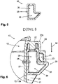
- the container collar 20 protrudes outwardly from the container side wall 13, whereby the container collar 20 is open pointing towards the container bottom, and wherein the container collar 20 provides a receiving space 21 which is adapted for interacting with a lifting device of a refuse collecting entity, the comb teeth of a comb lifting device in particular.
- the container collar 20 comprises a ridge element 22 which protrudes outwardly from the container side wall 13.
- the ridge element 22 is configured as a flat base element, from which, preferably at the ends thereof, other components protrude, perpendicular or almost perpendicular for example.
- One of these components is the container side wall 13.
- the container collar 22 comprises an outer leg 23 at a free end 22a of the ridge element 22.
- the outer leg 23 protrudes in a direction towards the container bottom 12, this direction being depicted with reference numeral 24 in Figure 6 .
- the receiving space 21 of the container collar 20 is limited by the ridge element 22, by the outer leg 23 and by a portion of the container side wall 13, a portion of front wall segment 13a in the present case.
- a number of reinforcement ribs 25 are provided in the receiving space 21.
- the blocking element 30 When the blocking element 30 was mounted to the waste container 10, which is shown in Figure 6 , the blocking element 30 is at least partially disposed inside the receiving space 21. In this state, the blocking element 30 at least partially enters the receiving space 21 from below and occupies the respective portion of the receiving space 21, such that this portion of the receiving space 21 under the container collar 20 is blocked, so the comb lifter teeth cannot enter the receiving space 21 anymore.
- the L-shaped blocking element 30 is disposed at the waste container 10 as follows:
- the blocking device 30 is detachably mounted to the container side wall 13. This can get realized by means of screws 26 for example.
- a first portion of the blocking element 30 is disposed inside the receiving space 21 of the container collar 20. This first portion is represented by the second portion 39 of the L-shaped blocking element 30. A second portion of the blocking element 30 is disposed outside the receiving space 21 of the container collar 20. This second portion is represented by the first base portion 36 of the blocking element 30.
- a first end face 37 of the first base portion 36 is directed to the container side wall 13, whilst a second, opposite end face 38 of the first base portion 36 is directed away from the container side wall 13.
- the second end face 38 is configured as a surface having an inclined course. This means, that the course of this surface differs from a perpendicular course. It is an advantage of such an angular surface, that the rigidity of the blocking element 30, in particular the rigidity of its bottom, which comes in direct contact with a comb tooth of the comb lifting device, increases. Furthermore, such an angular surface is capable of guiding the comb tooth of the comb lifting device away from the blocking element 30, and therefore away from the container collar 20.
- the second end face 38 is configured as a surface, which at least partially protrudes outwardly over the container collar 20.
- the blocking device 30 provides a small overhang beyond the container collar 20, which increases the distance from the lifting device to side wall 13 of the waste container 10, the front wall segment 13a for example.
- any damages to the waste container caused by the lifting device, by the comb teeth for example, are avoided.
- false activation of lifter sensors can be avoided.
Landscapes
- Engineering & Computer Science (AREA)
- Mechanical Engineering (AREA)
- Refuse Receptacles (AREA)
Priority Applications (1)
| Application Number | Priority Date | Filing Date | Title |
|---|---|---|---|
| EP20207746.7A EP4001172A1 (fr) | 2020-11-16 | 2020-11-16 | Récipient de déchets |
Applications Claiming Priority (1)
| Application Number | Priority Date | Filing Date | Title |
|---|---|---|---|
| EP20207746.7A EP4001172A1 (fr) | 2020-11-16 | 2020-11-16 | Récipient de déchets |
Publications (1)
| Publication Number | Publication Date |
|---|---|
| EP4001172A1 true EP4001172A1 (fr) | 2022-05-25 |
Family
ID=73452043
Family Applications (1)
| Application Number | Title | Priority Date | Filing Date |
|---|---|---|---|
| EP20207746.7A Pending EP4001172A1 (fr) | 2020-11-16 | 2020-11-16 | Récipient de déchets |
Country Status (1)
| Country | Link |
|---|---|
| EP (1) | EP4001172A1 (fr) |
Citations (5)
| Publication number | Priority date | Publication date | Assignee | Title |
|---|---|---|---|---|
| DE3636019A1 (de) * | 1986-04-28 | 1988-04-28 | Mehrkammer Muell System Gmbh | Schuettung an einem muellfahrzeug und muellbehaelter fuer diese schuettung |
| JPS63130406U (fr) * | 1987-02-13 | 1988-08-25 | ||
| EP1518800A1 (fr) | 2003-09-24 | 2005-03-30 | Sulo Umwelttechnik GmbH & Co. KG | Dispositif de préhension et récipient à ordures |
| DE102004001636A1 (de) | 2004-01-10 | 2005-08-11 | Hüffermann Entsorgungssysteme GmbH | Entsorgungsfahrzeug |
| EP2902342A1 (fr) * | 2012-07-20 | 2015-08-05 | Ros Roca, S.A. | Ensemble conteneur à déchets |
-
2020
- 2020-11-16 EP EP20207746.7A patent/EP4001172A1/fr active Pending
Patent Citations (5)
| Publication number | Priority date | Publication date | Assignee | Title |
|---|---|---|---|---|
| DE3636019A1 (de) * | 1986-04-28 | 1988-04-28 | Mehrkammer Muell System Gmbh | Schuettung an einem muellfahrzeug und muellbehaelter fuer diese schuettung |
| JPS63130406U (fr) * | 1987-02-13 | 1988-08-25 | ||
| EP1518800A1 (fr) | 2003-09-24 | 2005-03-30 | Sulo Umwelttechnik GmbH & Co. KG | Dispositif de préhension et récipient à ordures |
| DE102004001636A1 (de) | 2004-01-10 | 2005-08-11 | Hüffermann Entsorgungssysteme GmbH | Entsorgungsfahrzeug |
| EP2902342A1 (fr) * | 2012-07-20 | 2015-08-05 | Ros Roca, S.A. | Ensemble conteneur à déchets |
Similar Documents
| Publication | Publication Date | Title |
|---|---|---|
| US6050442A (en) | Multi-compartment containers, hinged lid and divider assemblies therefor, and hinge assemblies | |
| EP0559822B1 (fr) | Conteneur en plastique pour detritus | |
| US6019242A (en) | Multi-compartment container and lid therefor | |
| US7172088B2 (en) | Insert for a rollout type waste container and waste container assembly | |
| US9878846B2 (en) | Commercial waste container systems and methods | |
| US6676141B1 (en) | Alternative bin cart | |
| CA2699917A1 (fr) | Fonctions d'alignement pour un chariot | |
| US6357988B1 (en) | Segregated waste collection system | |
| DK166269B (da) | Kasse til renovationsvogn, og som har flere rum, og renovationsvogn forsynet med en saadan kasse | |
| US20080199290A1 (en) | Refuse and Recycling Collection System | |
| US4742933A (en) | Container of plastics material | |
| US5772061A (en) | Refuse containers | |
| US20120199590A1 (en) | Front-loading trash container with integrated rear trash can dumping mechanism | |
| EP4001172A1 (fr) | Récipient de déchets | |
| EP1117593B1 (fr) | Couvercle et bequille pivotante associee | |
| EP0648181A1 (fr) | Paroi de division pour une poubelle et procede de mise en place | |
| WO1999033717A1 (fr) | Adaptateur et procedes pour vider des bennes a ordures a chargement par l'extremite arriere en utilisant des vehicules a ordures a chargement par l'extremite avant | |
| US5868267A (en) | Refuse container lid | |
| WO1996039347A3 (fr) | Systeme collecteur pour produits destines au recyclage | |
| EP3313756B1 (fr) | Réceptacle pour déchets recyclables | |
| EP1323646A1 (fr) | Poubelle et système de ramassage d'ordures | |
| US5069343A (en) | Stackable recycling storage bin apparatus | |
| CA2730469A1 (fr) | Contenant a dechet a chargement par l'avant avec mecanisme de dechargement dudit contenant integre a l'arriere | |
| EP0579028B1 (fr) | Récipient d'insertion pour poubelle | |
| WO2007000791A1 (fr) | Poubelle domestique pour une collecte separee de dechets |
Legal Events
| Date | Code | Title | Description |
|---|---|---|---|
| PUAI | Public reference made under article 153(3) epc to a published international application that has entered the european phase |
Free format text: ORIGINAL CODE: 0009012 |
|
| STAA | Information on the status of an ep patent application or granted ep patent |
Free format text: STATUS: THE APPLICATION HAS BEEN PUBLISHED |
|
| AK | Designated contracting states |
Kind code of ref document: A1 Designated state(s): AL AT BE BG CH CY CZ DE DK EE ES FI FR GB GR HR HU IE IS IT LI LT LU LV MC MK MT NL NO PL PT RO RS SE SI SK SM TR |
|
| RIN1 | Information on inventor provided before grant (corrected) |
Inventor name: NOOYEN, MARK |
|
| STAA | Information on the status of an ep patent application or granted ep patent |
Free format text: STATUS: REQUEST FOR EXAMINATION WAS MADE |
|
| 17P | Request for examination filed |
Effective date: 20221125 |
|
| RBV | Designated contracting states (corrected) |
Designated state(s): AL AT BE BG CH CY CZ DE DK EE ES FI FR GB GR HR HU IE IS IT LI LT LU LV MC MK MT NL NO PL PT RO RS SE SI SK SM TR |
|
| RAP3 | Party data changed (applicant data changed or rights of an application transferred) |
Owner name: ESE WORLD B.V. |