EP4001173A1 - Système de levage pour un véhicule de collecte de déchets - Google Patents
Système de levage pour un véhicule de collecte de déchets Download PDFInfo
- Publication number
- EP4001173A1 EP4001173A1 EP21210225.5A EP21210225A EP4001173A1 EP 4001173 A1 EP4001173 A1 EP 4001173A1 EP 21210225 A EP21210225 A EP 21210225A EP 4001173 A1 EP4001173 A1 EP 4001173A1
- Authority
- EP
- European Patent Office
- Prior art keywords
- lower support
- lifting system
- lifting
- bin
- refuse
- Prior art date
- Legal status (The legal status is an assumption and is not a legal conclusion. Google has not performed a legal analysis and makes no representation as to the accuracy of the status listed.)
- Pending
Links
- 239000013536 elastomeric material Substances 0.000 claims description 6
- 230000006378 damage Effects 0.000 description 6
- 230000001419 dependent effect Effects 0.000 description 3
- 230000000452 restraining effect Effects 0.000 description 3
- 230000004888 barrier function Effects 0.000 description 2
- 230000035939 shock Effects 0.000 description 2
- 230000005484 gravity Effects 0.000 description 1
- 239000000463 material Substances 0.000 description 1
- 239000004033 plastic Substances 0.000 description 1
- 238000009877 rendering Methods 0.000 description 1
Images



Classifications
-
- B—PERFORMING OPERATIONS; TRANSPORTING
- B65—CONVEYING; PACKING; STORING; HANDLING THIN OR FILAMENTARY MATERIAL
- B65F—GATHERING OR REMOVAL OF DOMESTIC OR LIKE REFUSE
- B65F3/00—Vehicles particularly adapted for collecting refuse
- B65F3/02—Vehicles particularly adapted for collecting refuse with means for discharging refuse receptacles thereinto
- B65F3/04—Linkages, pivoted arms, or pivoted carriers for raising and subsequently tipping receptacles
- B65F3/041—Pivoted arms or pivoted carriers
-
- B—PERFORMING OPERATIONS; TRANSPORTING
- B65—CONVEYING; PACKING; STORING; HANDLING THIN OR FILAMENTARY MATERIAL
- B65F—GATHERING OR REMOVAL OF DOMESTIC OR LIKE REFUSE
- B65F3/00—Vehicles particularly adapted for collecting refuse
- B65F3/02—Vehicles particularly adapted for collecting refuse with means for discharging refuse receptacles thereinto
- B65F2003/0223—Vehicles particularly adapted for collecting refuse with means for discharging refuse receptacles thereinto the discharging means comprising elements for holding the receptacle
- B65F2003/023—Gripper arms for embracing the receptacle
- B65F2003/0233—Gripper arms for embracing the receptacle for embracing two or more receptacles
-
- B—PERFORMING OPERATIONS; TRANSPORTING
- B65—CONVEYING; PACKING; STORING; HANDLING THIN OR FILAMENTARY MATERIAL
- B65F—GATHERING OR REMOVAL OF DOMESTIC OR LIKE REFUSE
- B65F3/00—Vehicles particularly adapted for collecting refuse
- B65F3/02—Vehicles particularly adapted for collecting refuse with means for discharging refuse receptacles thereinto
- B65F2003/0223—Vehicles particularly adapted for collecting refuse with means for discharging refuse receptacles thereinto the discharging means comprising elements for holding the receptacle
- B65F2003/024—Means for locking the rim
-
- B—PERFORMING OPERATIONS; TRANSPORTING
- B65—CONVEYING; PACKING; STORING; HANDLING THIN OR FILAMENTARY MATERIAL
- B65F—GATHERING OR REMOVAL OF DOMESTIC OR LIKE REFUSE
- B65F3/00—Vehicles particularly adapted for collecting refuse
- B65F3/02—Vehicles particularly adapted for collecting refuse with means for discharging refuse receptacles thereinto
- B65F2003/0293—Means mounted on the vehicle for supporting the refuse receptacle in the tipping position
Definitions
- the present application relates to the field of refuse collection vehicles, in particular to a lifting system for a refuse collection vehicle.
- Refuse collection vehicles are used to pick up refuse at different collection points.
- the collections points e.g. of households, of companies, etc.
- the refuse at the collection points can be deposited outside in different ways, e.g. in a refuse bag, in a refuse bin, which may be small one with two wheels or a large one with four wheels.
- an operator usually arranges the bin at a lifting system arranged at the rear end of the refuse collection vehicle. The lifting system lifts the bin up and tilts the bin such that the refuse is emptied in the hopper of the refuse collection vehicle.
- the refuse collection vehicle drives to a refuse collection station to empty the collection body, after which the refuse collection vehicle is ready again for collecting refuse that is offered along the road.
- the lifting system has a so-called lifting chair provided with a comb to grip the top edge of the bin in order to lift and tilt the bin. Because the bins are usually made of plastic material, the edge or one of more walls of the bin could break when it is tilted by the lifting system. Therefore, the lifting system is provided with a support, which supports a side of the bin. The lower support pushes the bin via a tilting movement upwards to tilt the bin relative to the point where it is gripped by the gripper and tilts the bin so far that its bottom faces upward for emptying the refuse.
- the support is provided at the bottom of the lifting chair, such that the support is, relative to the road, the lowest point of the lifting system of the refuse collection vehicle when the lifting system is in a low position.
- the refuse collection vehicle drives from one collection point to another collection point.
- the lifting system can be raised to a high position in order to create more ground clearance.
- the travelling distance between the different collection points is rather short, e.g. in a densely populated residential street or area, the lifting system should also be raised during travelling, but the operators prefer to leave the lifting system in a low position or may forget to raise the lifting system. Leaving the lifting system in low position, makes the collection of refuse more efficient without wasting time with lowering and raising of the lifting system.
- the refuse collection vehicles drives forward and the lifting system is still in a low position, the surface of the road, e.g.
- a lifting system for a refuse collection vehicle the lifting system being configured to be arranged at the rear of the vehicle, wherein the lifting system comprises:
- the invention thus relates to a lifting system for a refuse collection vehicle, which further in the description is also referred to as vehicle.
- the refuse collection vehicle is configured to collect refuse.
- the lifting system may in practice be arranged at the rear of the vehicle.
- the lifting system comprises a lifting chair.
- the lifting chair comprises a gripper, such, as a comb, which is configured to grip a refuse bin.
- the gripper is arranged at the top end of the lifting chair.
- the comb is arranged under the flange of the bin in order to grip the bin.
- the invention is not limited to one type of refuse bin. Also, other types of refuse bins are applicable, e.g. with different dimensions and/or volume.
- refuse bins - in practise also called 'bins' - up to about 400 litres - such as a 60 litres, a 80 litres, a 140 litres, a 240 litres, and a 360 litres refuse bin - have in general two wheels, two corners of the bottom each having one wheel, and that refuse bins - in practise in general called 'containers' - from about 500 litres to about 1300 litres - such as 660 litres, 770 litres, and 1100 litres refuse bins - have in general 4 wheels, one at each corner of the bottom.
- bins are in practise standardized, at least per region, and the refuse collection vehicles in a region are provided with handling adapters in correspondence with the 'standardized' bins used in that region.
- handling adapters especially concern the so-called lifting chair and locking system.
- the invention may be used with all these types of bins as well other types of bins, like bins without wheels.
- the term 'bin' as used in this application comprises containers as well, in other words the term 'bin' as used in this application comprises the term 'bin' as used in practise as well as the term 'container' as used in practise.
- the lifting chair is moveable relative to the vehicle between a receiving condition and an emptying condition.
- the lifting chair In the receiving condition, the lifting chair is intended to be used to grip the refuse bin.
- a height axis of the refuse bin is about vertical and an upper side of the bin is arranged higher than the lower side of the bin.
- the upper side of the bin may e.g. comprise a hinged cover for the top of the bin.
- at the lower side of the bin at least a pair of wheels are provided to move the bin.
- the lifting chair is intended to be used to tilt the refuse bin.
- the refuse bin In the emptying condition, the refuse bin is tilted around a horizontal axis so that the height axis of the refuse bin slants with respect to a horizontal plane and the upper side of the bin is arranged lower than the lower side of the bin.
- the horizontal plane is parallel with the road surface.
- the lifting chair which grips the bin can be shaken a couple of times in the emptying condition to ensure that the bin is completely emptied.
- the lifting system further comprises a lower support, also called pushing support.
- the lower support is arranged at the bottom of the lifting chair.
- the lower support is configured to push and/or support the refuse bin when the refuse bin is moved to the tilted emptying condition.
- the lower support is configured to make contact with a side surface of the bin, e.g. the front side surface.
- the position of the lower support relative to the bin is defined by ISO or EN standards.
- the lower support pushes and/or supports the bin at the side surface during its tilting movement and pushes and/or supports it so far that the refuse bin gets into its tilted emptying condition.
- the lower support may e.g. be provided with a pad.
- This pad serves to distribute the supporting and/or pushing force of the lower support on the refuse bin.
- the pad on the lower support ensures that the executed supporting and/or pushing force is about equally distributed over the contact surface at the refuse bin to prevent cracks in the refuse bin.
- the pad is made of or comprises an elastomeric material, such as a rubber.
- the lifting system is configured to allow the lower support to move around a horizontal swing axis from a vertical position, in a backward swing direction opposite to a forward driving direction of the vehicle, to a horizontal position.
- the lifting system according to the invention is thus configured to allow the lower support to swing aside in the backward direction, when the vehicle drives in forward direction and the lower support hits an obstacle on the road, e.g. a road bump.
- the lower support hits an obstacle on the road, it folds up and creates more ground clearance. This ensures that damage of the lifting system is prevented and that collection of refuse may continue without the refuse collection vehicle needing to return to its base for any repair.
- the lifting system is further configured to restrain the lower support from returning to the vertical position after the lower support has rotated from the vertical position, in the backward swing direction, around the horizontal swing axis. Restraining the lower support from returning prevents uncontrolled returning, which may cause damage to the lifting device or injuries to persons adjacent the lifting device. Restraining the lower support from returning may for example be achieved by means of a releasable ratchet.
- the ratchet - being a mechanism having a bar or wheel with inclined teeth into which a pawl drops so that motion of the bar or wheel is allowed in one direction and prevented in the other direction - allows rotation of the lower support in the backward swing direction and prevents the lower support from returning in a direction opposite to the backward swing direction.
- the ratchet By retracting the pawl, the ratchet is released which allows the lower support to return.
- restraining the lower support from returning may be achieved by means of friction. In order to return the lower support, this friction then has to be overcome by a force larger than the friction or a friction member causing the friction has to be released with respect to the lower support.
- the lifting system comprises a friction system configured to arrest rotation of the lower support with respect to the lifting chair such that the lower support is kept motionless, with respect to the lifting chair, in its position once the lower support has been rotated around the horizontal swing axis.
- a friction system arresting rotation of the lower support prevents so to say the lower support from any swinging except swinging due to a large force caused by hitting an obstacle. This reduces the risk of people getting injured and ensures that the lower support is - as long as no obstacle has been hit - always in vertical position when the lifting chair is in receiving condition.
- Such a friction system will allow the lower support to rotate in the backward swing direction in case it hits an obstacle, but prevents it from a) returning in a forward swing direction, and from b) swinging - such as swinging to-and-fro - due to for example shocks or vibrations caused by the road or vehicle.
- an operator may do so hands or feet by exerting a force onto the lower support which is sufficient to overcome the friction of the friction system.
- the friction system is configured to allow a hampered movement of the lower support between the vertical and horizontal position to prevent the lower support from:
- the lifting system is configured to prevent the lower support, when in the receiving condition and with the lower support in the vertical position, from moving around the horizontal swing axis in a direction opposite to the backward swing direction.
- the lower support thus can only swing in one direction.
- the lower support may be provided with a plate at the top, which extends upwards behind the lifting chair relatively seen from the receiving side. Since the plate of the lower support contacts the back of the lifting chair when the lower support is in the vertical position, it is for the lower support not possible to swing in the direction opposite to the backward swing direction.
- the lifting system is configured to prevent the lower support, when moving a bin from the receiving condition to the emptying condition, from moving around the swing axis in a direction opposite to the backward swing direction.
- the lower support could swing down, e.g. due to the gravitational force.
- this ensures that the lower support continuously supports and/or pushes the refuse bin during the movement from the receiving condition to the emptying condition.
- This can also be achieved by providing the lower support with a plate at the top, which extends behind the lifting chair. The back of the lifting chair then serves as a stop against which the plate, provided at the top of the lower support, may rest.
- the lower support is mounted to the lifting chair by at least one hinge.
- the hinge provides the horizontal swing axis.
- the hinge allows the swing of the lower support relative to the lifting chair in backward swing direction.
- the hinge has at least one hinge pin or bendable section providing the horizontal swing axis.
- the bendable section is made of or comprises an elastomeric material, such as a rubber.
- the hinge allows that the lower support folds upwards from the vertical position to the horizontal position.
- the hinge ensures that the lower support in the horizontal position automatically, e.g. due to gravitational force, falls back to the vertical position.
- the hinge may be made of or may comprise a return spring, which may be adapted to lock, temporary, the lower support in the horizontal position.
- the at least one hinge is a friction hinge.
- a friction hinge is a hinge that offers resistance to the pivoting motion of the hinge. That resistance can be such that it slows the movement or that it actually arrests movement to the extent that the pivoting object is held motionless in the position it has been brought in.
- a friction hinge reduces the risk of people getting injured and assists the lower support being in vertical position when the lifting chair is in receiving condition.
- the friction hinge is configured to arrest rotation of the lower support with respect to the lifting chair such that the lower support is kept motionless in its position once the lower support has been rotated around the horizontal swing axis.
- the horizontal swing axis is arranged at the lower end of the lifting chair.
- the lower support mounted at the bottom of the lifting chair in the vertical position defines the ground clearance between bottom of the lower support and the road.
- the horizontal swing axis is arranged, when the lifting chair is in receiving condition, at about 35 cm to about 70 cm, such as about 40 cm to about 50 cm or about 40 cm to about 60 cm, above a road surface spanned by the location where wheels of the vehicle contact the road.
- the invention further relates to a refuse collection vehicle, wherein the vehicle comprises:
- the lifting system tilts a refuse bin in an emptying condition.
- the refuse bin In the emptying condition, the refuse bin is tilted around a horizontal axis so that the height axis of the refuse bin slants with respect to a horizontal plane, wherein the refuse bin is upside down and the refuse falls down into a hopper of the tailgate.
- the hopper feeds or guides the refuse to the collection body. Once the refuse bin is emptied in the hopper, the refuse is pressed, e.g. under hydraulic pressure, from the hopper towards the collection body.
- the lifting system may still be configured to be raised from a low position for accepting bins to be emptied to a high transport position for traveling over longer distances, and to be lowered from the high position to the low position. But, with the lifting device according to this invention, this raising and lowering of the lifting device can be omitted.
- the lifting system exclusive the lower support defines a main part of the lifting system, and the horizontal swing axis is arranged at the lower end of the main part.
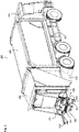
- Fig. 1 schematically illustrates a lifting system 101 according to the invention for a refuse collection vehicle 100.
- the refuse collection vehicle 100 comprises a chassis 102, a driver's cab 103, a collection body 104 for collecting refuse and a tailgate 105.
- the driver's cab 103 is provided on the chassis 102, at the front of the chassis 102.
- the collection body 104 is provided on the chassis 102, behind the driver's cab 103.
- the tailgate 105 is provided at the rear side of the chassis 102 with the collection body 104 arranged between the tailgate 105 and the driver's cab 103.
- the tailgate 105 comprises the lifting system 101.
- the lifting system comprises a lifting chair 106.
- the lifting chair comprises a gripper at the top end of the lifting chair.
- the gripper is configured to grip a refuse bin.
- the gripper comprises a comb 107 and locking system 108.
- the comb 107 grips under the flanged edge of the bin and the locking system 108 locks on top of this flanged edge to cooperate in locking action with the comb 107.
- the lifting chair 106 is moveable relative to the vehicle 100 between a receiving condition and an emptying condition. In Fig. 1 , the lifting chair 106 is in the receiving condition. In the receiving condition, the lifting chair 106 is intended to be used to grip the refuse bin (see Fig. 2 ).
- a height axis of the refuse bin is about vertical and an upper side of the bin is arranged higher than the lower side of the bin (see Fig. 3 ).
- the lifting system 101 further comprises a control panel 109 to control the movement of the lifting chair.
- a control panel 109 to control the movement of the lifting chair.
- safety barriers 110 are provided at the sides of the lifting system. The safety barriers are provided to avoid a person to walk into the area where refuse bins are tilted.
- the lifting system 101 further comprises a lower support 111.
- the lower support is arranged at the bottom of the lifting chair 106. The distance between the lower support 111 and the ground surface defines the ground clearance 112.
- the lower support is configured to push and/or support the refuse bin when the refuse bin is moved to the tilted emptying condition.
- the lower support is provided with a pad 111a. This pad 111a serves to distribute the supporting and/or pushing force of the lower support on the refuse bin.
- the pad on the lower support ensures that the executed supporting and/or pushing force is about equally distributed over the contact surface at the refuse bin to prevent cracks in the refuse bin.
- the pad is made of or comprises an elastomeric material, such as a rubber.
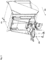
- Fig. 2 schematically illustrates the lifting system in the receiving condition as illustrated in Fig. 1 , wherein the lifting system grips a refuse bin 200.
- the lifting chair comprises a comb at the top end of the lifting chair.
- the gripper may be a comb with a plurality of teeth (not clearly visible in Fig. 2 ), which are at a distance from each other arranged along the top end of the lifting chair.
- the comb grips under the flange of the refuse bin.
- the locking system 108 locks the upper side of the flange to lock the flange between the comb and the locking system 108.
- a height axis of the refuse bin is about vertical and an upper side of the bin is arranged higher than the lower side of the bin.
- the upper side of the refuse bin is a hinged cover for the top of the bin.
- a pair of wheels are provided to move the bin, e.g. to move the bin towards the gripper.
- the invention is not limited to one type of refuse bin. Also, other types of refuse bins are applicable, e.g. with different dimensions and/or volume.
- the lower support is configured to make contact with the front side surface of the refuse bin. The position of the lower support relative to the bin is defined by ISO or EN standards.
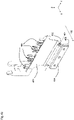
- Fig. 3 schematically illustrates the lifting system as illustrated in Fig. 2 , wherein the lifting chair is moved to an emptying condition.
- the refuse bin In the emptying condition, the refuse bin is tilted around a horizontal axis so that the height axis of the refuse bin slants with respect to a horizontal plane and the upper side of the bin is arranged lower than the lower side 301 of the bin.
- the horizontal plane is parallel with the road surface. Due to the gravitational force, the content of the bin falls down into a hopper 113 of the tailgate (see also Fig. 1 ).
- the hopper 113 is a refuse collector area. Once the refuse bin is emptied in the hopper, the refuse is pressed, e.g.
- the lifting chair which grips the bin can be moved a couple of times from the receiving condition to the emptying condition to ensure that the bin is completely emptied.
- the lower support pushes and/or supports the bin at the front side surface 302 via a tilting movement upwards (see figure 3 ).
- the lower support pushes and/or supports the refuse bin up to in its emptying condition.
- the lifting system prevents the lower support, when moving the bin from the receiving condition to the emptying condition, from moving around a horizontal swing axis 300 in a direction opposite to a backward swing direction 201 (see also Fig. 2 ).
- the backward swing direction is opposite to the forward driving direction of the vehicle.
- the lifting system 101 exclusive the lower support 111 defines a main part of the lifting system 101.
- the horizontal swing axis 300 is, when the lifting chair is in receiving condition, arranged at the lower end of the main part.
- the swing axis 300 is, when the lifting chair is in receiving condition, arranged at about 35 cm to about 70 cm, for example about 40-50 cm or about 40-60 cm, above a road spanned by the location where wheels of the vehicle contact the road.
- the lower support When the lifting system is moved to the emptying condition like in Fig. 3 , the lower support could swing down, e.g. due to the gravitational force. By preventing the movement around the horizontal swing axis in the direction opposite to the backward swing direction 201, it ensures that the lower support continuously supports and/or pushes the refuse bin during the movement from the receiving condition to the emptying condition.
- Fig. 4a schematically illustrates a lower support 400 according to the invention in more detail, wherein the lower support 400 is in a vertical position (see also Fig. 4b ).
- the lower support 400 is mounted to the bottom of the lifting chair 401 by a hinge 402.
- the lifting chair 401 includes a comb having a plurality of teeth 403, which are at a distance from each other arranged along the top end of the lifting chair 401.
- the hinge 402 provides a horizontal swing axis 404, i.e. along the y-axis (see the indicated xyz coordinate system).
- the hinge 402 allows the swing of the lower support 400 relative to the lifting chair 401 in backward swing direction 405, i.e.
- the hinge 402 has a hinge pin providing the horizontal swing axis 404.
- the hinge 402 may have no hinge pin but a different member allowing hinging. The hinge allows that the lower support folds upwards from the vertical position to the horizontal position (see Figs. 5a-5b ).
- Fig. 4b shows the lower support 400 of Fig. 4a in a vertical cross-sectional view.
- the lower support 400 is provided with a pad 406.
- This pad 406 serves to distribute the supporting and/or pushing force of the lower support 400 on a refuse bin.
- the pad 406 on the lower support 400 ensures that the executed supporting and/or pushing force is about equally distributed over the contact surface at the refuse bin to prevent cracks in the refuse bin.
- the pad 406 is made of or comprises an elastomeric material, such as a rubber.
- the lifting system is configured to prevent the lower support in the vertical position, from moving around the horizontal swing axis 404 in a direction opposite to the backward swing direction 405.
- the lower support 400 is provided with a plate 407 at the top, which extends upwards behind the lifting chair 401. Since the plate 407 of the lower support 400 contacts the back of the lifting chair 401 when the lower support is in the vertical position, it is for the lower support not possible to swing in the direction opposite to the backward swing direction 405.
- the lower support 400 thus can only swing in one direction. By preventing the lower support 400 from swinging in the direction opposite to the backward swing direction 405, it is ensured that rattling of the lower support 400 is prevented during the forward movement of the vehicle.
- Fig. 5a schematically illustrates the lower support 400 according to the invention in more detail, wherein the lower support 400 is in a horizontal position (see also Fig. 5b ).
- the lifting chair 401 is in the receiving condition.
- the lower support 400 has moved around the horizontal swing axis 404 from a vertical position, in the backward swing direction 405 opposite to a forward driving direction of the vehicle, to the horizontal position.
- the vehicle drives in forward direction and the lower support hits an obstacle on the road, e.g. a road bump, it folds up and creates more ground clearance. This ensures that damage of the lifting system is prevented and that collection of refuse may continue.
- Fig. 5b shows the lower support 400 of Fig. 5a in a vertical cross-sectional view.
- the hinge 402 ensures that the lower support 400 in the horizontal position automatically, e.g. due to gravitational force, falls back to the vertical position.
- the hinge 402 can be configured as a friction hinge by tightening the bolts - forming the hinge pins - sufficiently and/or by providing the hinge with friction members, such as friction rings.
Landscapes
- Engineering & Computer Science (AREA)
- Mechanical Engineering (AREA)
- Refuse-Collection Vehicles (AREA)
Applications Claiming Priority (1)
| Application Number | Priority Date | Filing Date | Title |
|---|---|---|---|
| NL2026964A NL2026964B1 (en) | 2020-11-24 | 2020-11-24 | Lifting system for a refuse collection vehicle |
Publications (1)
| Publication Number | Publication Date |
|---|---|
| EP4001173A1 true EP4001173A1 (fr) | 2022-05-25 |
Family
ID=74557227
Family Applications (1)
| Application Number | Title | Priority Date | Filing Date |
|---|---|---|---|
| EP21210225.5A Pending EP4001173A1 (fr) | 2020-11-24 | 2021-11-24 | Système de levage pour un véhicule de collecte de déchets |
Country Status (2)
| Country | Link |
|---|---|
| EP (1) | EP4001173A1 (fr) |
| NL (1) | NL2026964B1 (fr) |
Cited By (1)
| Publication number | Priority date | Publication date | Assignee | Title |
|---|---|---|---|---|
| CN119408874A (zh) * | 2024-12-13 | 2025-02-11 | 中建三局集团(深圳)有限公司 | 一种环保型智能建筑垃圾箱及其垃圾收运方法 |
Citations (3)
| Publication number | Priority date | Publication date | Assignee | Title |
|---|---|---|---|---|
| DE1024009B (de) * | 1956-06-18 | 1958-02-06 | Hans Zoeller | Kippvorrichtung fuer Muelltonnen |
| EP1955970A1 (fr) * | 2007-02-09 | 2008-08-13 | Terberg Machines B.V. | Procédé pour la fabrication d'une partie de support d'un dispositif de préhension faisant partie d'un dispositif de chargement pour vider un récipient dans un véhicule tel qu'un camion de collecte de déchets |
| EP3184470A1 (fr) * | 2015-12-21 | 2017-06-28 | Terberg Machines B.V. | Système de chargement pour vider un récipient, véhicule ainsi pourvu et procédé associé |
-
2020
- 2020-11-24 NL NL2026964A patent/NL2026964B1/en active
-
2021
- 2021-11-24 EP EP21210225.5A patent/EP4001173A1/fr active Pending
Patent Citations (3)
| Publication number | Priority date | Publication date | Assignee | Title |
|---|---|---|---|---|
| DE1024009B (de) * | 1956-06-18 | 1958-02-06 | Hans Zoeller | Kippvorrichtung fuer Muelltonnen |
| EP1955970A1 (fr) * | 2007-02-09 | 2008-08-13 | Terberg Machines B.V. | Procédé pour la fabrication d'une partie de support d'un dispositif de préhension faisant partie d'un dispositif de chargement pour vider un récipient dans un véhicule tel qu'un camion de collecte de déchets |
| EP3184470A1 (fr) * | 2015-12-21 | 2017-06-28 | Terberg Machines B.V. | Système de chargement pour vider un récipient, véhicule ainsi pourvu et procédé associé |
Cited By (1)
| Publication number | Priority date | Publication date | Assignee | Title |
|---|---|---|---|---|
| CN119408874A (zh) * | 2024-12-13 | 2025-02-11 | 中建三局集团(深圳)有限公司 | 一种环保型智能建筑垃圾箱及其垃圾收运方法 |
Also Published As
| Publication number | Publication date |
|---|---|
| NL2026964B1 (en) | 2022-07-04 |
Similar Documents
| Publication | Publication Date | Title |
|---|---|---|
| US9126755B2 (en) | Apparatus for inverting an object | |
| US5901874A (en) | Handicapped accessible dumpster | |
| US4155584A (en) | Automatic locking mechanism for refuse container | |
| US5011036A (en) | Front loading, foot operated refuse bin | |
| US5702225A (en) | Boomless automated side loader for refuse collection vehicle having lift arm with non-extendable upper end | |
| US20060280582A1 (en) | System for automatically capturing a fully loaded refuse container, and without any spillage, empty the contents of the refuse container into a refuse collection vehicle | |
| US3738516A (en) | Container lifting mechanism | |
| US7083060B2 (en) | Universal dumpster | |
| US3270900A (en) | Automatic bin dumping apparatus | |
| US5651654A (en) | Tilting bin handler | |
| US5361978A (en) | Waste receptacle | |
| US6705825B2 (en) | Lift gate device | |
| US6854949B2 (en) | Refuse collection vehicle with pendular packing device and refuse ejection system | |
| EP4001173A1 (fr) | Système de levage pour un véhicule de collecte de déchets | |
| EP0257925B1 (fr) | Réceptacle à auto-vidage | |
| US4838752A (en) | Forklift attachment for dumping containers | |
| US6921239B2 (en) | Damage-resistant refuse receptacle lifter | |
| WO2007115370A1 (fr) | chariot | |
| US3262589A (en) | Refuse disposal | |
| JP2005041461A (ja) | エスカレータカート | |
| CN210150577U (zh) | 一种防撞伤的c型吊具 | |
| US2823818A (en) | Bin and truck refuse disposal device | |
| US3094231A (en) | Front end loaders | |
| ES2286198T3 (es) | Sistema de recogida de basura. | |
| JP4212145B2 (ja) | コンテナ積載用貨物自動車 |
Legal Events
| Date | Code | Title | Description |
|---|---|---|---|
| PUAI | Public reference made under article 153(3) epc to a published international application that has entered the european phase |
Free format text: ORIGINAL CODE: 0009012 |
|
| STAA | Information on the status of an ep patent application or granted ep patent |
Free format text: STATUS: THE APPLICATION HAS BEEN PUBLISHED |
|
| AK | Designated contracting states |
Kind code of ref document: A1 Designated state(s): AL AT BE BG CH CY CZ DE DK EE ES FI FR GB GR HR HU IE IS IT LI LT LU LV MC MK MT NL NO PL PT RO RS SE SI SK SM TR |
|
| STAA | Information on the status of an ep patent application or granted ep patent |
Free format text: STATUS: REQUEST FOR EXAMINATION WAS MADE |
|
| 17P | Request for examination filed |
Effective date: 20221118 |
|
| RBV | Designated contracting states (corrected) |
Designated state(s): AL AT BE BG CH CY CZ DE DK EE ES FI FR GB GR HR HU IE IS IT LI LT LU LV MC MK MT NL NO PL PT RO RS SE SI SK SM TR |
|
| 19U | Interruption of proceedings before grant |
Effective date: 20231122 |
|
| 19W | Proceedings resumed before grant after interruption of proceedings |
Effective date: 20241202 |
|
| RAP3 | Party data changed (applicant data changed or rights of an application transferred) |
Owner name: HALLER BENELUX B.V. |