EP4001180B1 - Dispositif et procédé de distribution de sacs de transport dans une technique de transport d'une installation de transport suspendu, ainsi qu'une telle installation de transport suspendu - Google Patents
Dispositif et procédé de distribution de sacs de transport dans une technique de transport d'une installation de transport suspendu, ainsi qu'une telle installation de transport suspendu Download PDFInfo
- Publication number
- EP4001180B1 EP4001180B1 EP21207748.1A EP21207748A EP4001180B1 EP 4001180 B1 EP4001180 B1 EP 4001180B1 EP 21207748 A EP21207748 A EP 21207748A EP 4001180 B1 EP4001180 B1 EP 4001180B1
- Authority
- EP
- European Patent Office
- Prior art keywords
- hanging
- conveying
- transport
- adapters
- conveyor system
- Prior art date
- Legal status (The legal status is an assumption and is not a legal conclusion. Google has not performed a legal analysis and makes no representation as to the accuracy of the status listed.)
- Active
Links
Images



Classifications
-
- B—PERFORMING OPERATIONS; TRANSPORTING
- B65—CONVEYING; PACKING; STORING; HANDLING THIN OR FILAMENTARY MATERIAL
- B65G—TRANSPORT OR STORAGE DEVICES, e.g. CONVEYORS FOR LOADING OR TIPPING, SHOP CONVEYOR SYSTEMS OR PNEUMATIC TUBE CONVEYORS
- B65G47/00—Article or material-handling devices associated with conveyors; Methods employing such devices
- B65G47/52—Devices for transferring articles or materials between conveyors i.e. discharging or feeding devices
- B65G47/60—Devices for transferring articles or materials between conveyors i.e. discharging or feeding devices to or from conveyors of the suspended, e.g. trolley, type
- B65G47/61—Devices for transferring articles or materials between conveyors i.e. discharging or feeding devices to or from conveyors of the suspended, e.g. trolley, type for articles
-
- B—PERFORMING OPERATIONS; TRANSPORTING
- B65—CONVEYING; PACKING; STORING; HANDLING THIN OR FILAMENTARY MATERIAL
- B65G—TRANSPORT OR STORAGE DEVICES, e.g. CONVEYORS FOR LOADING OR TIPPING, SHOP CONVEYOR SYSTEMS OR PNEUMATIC TUBE CONVEYORS
- B65G17/00—Conveyors having an endless traction element, e.g. a chain, transmitting movement to a continuous or substantially-continuous load-carrying surface or to a series of individual load-carriers; Endless-chain conveyors in which the chains form the load-carrying surface
- B65G17/20—Conveyors having an endless traction element, e.g. a chain, transmitting movement to a continuous or substantially-continuous load-carrying surface or to a series of individual load-carriers; Endless-chain conveyors in which the chains form the load-carrying surface comprising load-carriers suspended from overhead traction chains
-
- B—PERFORMING OPERATIONS; TRANSPORTING
- B65—CONVEYING; PACKING; STORING; HANDLING THIN OR FILAMENTARY MATERIAL
- B65G—TRANSPORT OR STORAGE DEVICES, e.g. CONVEYORS FOR LOADING OR TIPPING, SHOP CONVEYOR SYSTEMS OR PNEUMATIC TUBE CONVEYORS
- B65G43/00—Control devices, e.g. for safety, warning or fault-correcting
- B65G43/08—Control devices operated by article or material being fed, conveyed or discharged
-
- B—PERFORMING OPERATIONS; TRANSPORTING
- B65—CONVEYING; PACKING; STORING; HANDLING THIN OR FILAMENTARY MATERIAL
- B65G—TRANSPORT OR STORAGE DEVICES, e.g. CONVEYORS FOR LOADING OR TIPPING, SHOP CONVEYOR SYSTEMS OR PNEUMATIC TUBE CONVEYORS
- B65G2201/00—Indexing codes relating to handling devices, e.g. conveyors, characterised by the type of product or load being conveyed or handled
- B65G2201/02—Articles
- B65G2201/0229—Clothes, clothes hangers
Definitions
- the invention relates to a device and a method for placing transport bags into a conveyor system of an overhead conveyor system and to such an overhead conveyor system.
- US 2018/0118471 A1 discloses a transport device for goods carriers.
- the US 2018/0118471 A1 also discloses a device for placing hanging adapters in a conveyor system of a hanging conveyor system according to the preamble of claim 1.
- US 2015/0274425 A1 discloses a device for space-saving arrangement of hanging goods.
- US 2015/0210482 A1 discloses a conveying device for the automated conveying of individual goods.
- EN 10 2019 215 304 B3 discloses a hanging conveyor system with a device for feeding hanging goods into the hanging conveyor system.
- the respective thickness of individual hanging goods is determined by means of a detection unit.
- the hanging goods are separated by a feeding unit and fed into a conveyor system of the hanging conveyor system with a variable transport distance depending on the detected thickness.
- the detection of the thickness of the individual hanging goods is time-consuming and complex.
- the conveyor rail is designed to be coupled to the conveyor system in terms of conveyor technology.
- the hanging adapters are conveyed hanging along the conveyor rail. This can be done, for example, due to gravity, by arranging the conveyor rail at an angle to the horizontal that is different from zero.
- the angle of inclination is in particular not more than 25°, in particular not more than 20°, in particular not more than 15°, in particular between 1° and 12° and in particular between 1° and 10°.
- the conveyor technology features a fixed drive for the transport of the hanging adapters and thus the transport bags.
- a detection unit that has a signal connection to a control unit is used to record the number of hanging adapters in the detection area.
- the signal connection can be wired or wireless, in particular using radio technology.
- the control unit is set up to variably set the transport distance for conveying the transport bags using the conveyor technology.
- the transport distance is in particular a minimum transport distance.
- the transport distance is determined in particular depending on the number of hanging adapters. In particular, an average distance between neighboring hanging adapters is calculated from the number of hanging adapters.
- a separation unit is in signal connection with the control unit, which is used to feed the hanging adapters into the conveyor system one at a time.
- the signal connection between the control unit and the separation unit can be wired or wireless.
- the conveyor rail can have a continuously differentiable course along the conveying direction.
- the transition area to the section of the conveyor rail which is designed for the gravity-related conveying of the hanging adapters, in particular is oriented at an angle to the horizontal can have a continuously differentiable course, in particular it can be formed without kinks.
- the conveyor rail and/or the at least one hanging adapter preferably comprise a metal, in particular aluminum and/or steel, in particular they consist thereof.
- a detection sensor enables advantageous, in particular contactless, detection of the hanging adapters.
- the contactless detection of the hanging adapter enables collision-free and rapid detection of the adapters. This avoids any impairment of the conveying process.
- the detection sensors and in particular the detection unit increase the reliability and efficiency of the hanging conveyor system.
- a detection sensor is arranged in particular in the area of the conveyor rail, in particular attached to the conveyor rail.
- the detection sensor is axially fixed in the longitudinal direction of the conveyor rail. It can be advantageous to fix the detection sensor axially variable with respect to the conveyor rail.
- the detection sensor defines the detection area on the conveyor rail.
- the detection sensor is arranged relative to the conveyor rail in such a way that the detection sensor can directly detect the hanging adapters conveyed along the conveyor rail.
- the at least one detection sensor can be designed to detect at least one hanging adapter and/or at least one means of transport, in particular at least one transport bag.
- the hanging adapter is preferably a roller adapter.
- the detection of the hanging adapter can, in particular due to its known geometry and/or its defined bearing on the conveyor rail, particularly robust and reliable.
- An embodiment of a detection sensor according to claim 3 has proven to be particularly advantageous.
- An optical sensor in particular in the form of a light barrier, is designed in a straightforward manner. Since it has been recognized that it is sufficient to determine the presence of a hanging adapter, the design of the detection sensor as an optical sensor, in particular as a light barrier, is sufficient.
- a light barrier comprises in particular a transmitting element and a receiving element. The transmitting element sends out an optical signal that is received by the corresponding receiving element. In this case, there is no hanging adapter between the transmitting element and the receiving element. If no optical signal is received, this means that an object, i.e. a hanging adapter, is arranged between the transmitting element and the receiving element.
- the transmitting element and the corresponding receiving element are arranged on both sides below the conveyor rail.
- a light propagation direction of the optical signal of the transmitting element is oriented transversely and in particular perpendicularly to the conveying direction of the hanging adapter.
- Hanging adapters that are conveyed along the conveyor rail must pass through the optical signal of the light barrier. This reliably ensures that each hanging adapter is detected by a detection sensor.
- the light barriers can also be designed as reflection light barriers.
- each detection sensor has a transmitting/receiving element and a corresponding reflection element.
- the transmitting/receiving element sends an optical signal to the reflection element, which is then reflected back to the transmitting/receiving element.
- the at least one detection sensor can also be designed as a line camera with a CCD, CMOS, NMOS or InGaAs sensor.
- the line camera is designed in such a way that it has a width that corresponds to the width of the detection area. In particular, it can therefore be sufficient to use just a single sensor.
- An area camera can also be used instead of the line camera.
- the detection sensor can be designed as an RFID sensor, which can communicate in particular with the hanging adapter, in particular with an RFID chip arranged or integrated in and/or on the hanging adapter.
- the detection sensor can be designed as an RFID sensor, which can communicate in particular with the hanging adapter, in particular with an RFID chip arranged or integrated in and/or on the hanging adapter.
- further data of the hanging adapter and in particular of the transport bag conveyed hanging on the hanging adapter can be recorded.
- the data stored in the hanging adapter also contain data on the transport bag, in particular on the goods conveyed in the transport bag. It is particularly conceivable that conclusions can be drawn about the thickness of the transport bag from the data on the goods conveyed. This data can be used to verify when recording the transport distance.
- the transport distance based on the data on the goods conveyed in the transport bag.
- a maximum possible thickness of the goods to be transported in the transport bag is understood to be the largest dimension in the case of a cuboid-shaped package.
- the maximum dimension is the diameter of the sphere.
- the detection sensor can also be designed as an inductive and/or capacitive proximity sensor.
- the at least one detection sensor can be designed as a contact sensor.
- the detection sensor can be designed, for example, as a switch, in particular as a button.
- the detection sensor can be arranged on the conveyor rail in such a way that the respective hanging adapter can be contacted, in particular individually.
- the switching of the at least one detection sensor preferably takes place through contact with the hanging adapter, in particular due to an electrical connection established thereby and/or due to a relative movement between the hanging adapter and the detection sensor.
- the at least one detection sensor can also be designed as an acoustic sensor, in particular as a microphone, in particular for detecting running noises of the hanging adapter.
- a plurality of detection sensors enable direct detection of the number of hanging adapters in the detection area.
- at least two, in particular at least three, in particular at least four, in particular at least six, in particular at least eight, in particular at least ten, in particular at least fifteen and in particular up to one hundred detection sensors are provided.
- the detection sensors are arranged next to one another along the conveyor rail, in particular in a line grid.
- the line grid is oriented in particular parallel to a conveying direction predetermined by the conveyor rail.
- the length of the line grid along the conveying direction specifies the size, in particular the width, of the detection area along the conveying direction.
- the detection sensors are arranged in the line grid with, in particular identical, grid spacings from one another.
- the grid spacings are in particular set in such a way that a hanging adapter arranged on the conveyor rail within the detection area is detected without error by one of the detection sensors.
- the detection sensors are in particular designed as light barriers.
- the detection sensors form a so-called light grid.
- the detection sensors enable direct and uncomplicated detection of the number of hanging adapters, i.e. a so-called fill level of the detection area.
- a switchable stop element simplifies the loading of the hanging adapters into the conveyor system with the variable, settable transport distance.
- the stop element can preferably be switched between a blocking position in which a hanging adapter adjacent to the stop element is blocked on the conveyor rail, and a release position in which a hanging adapter adjacent to the stop element is released for conveyance from the conveyor rail into the conveyor system.
- the stop element can interact with the respective hanging adapter in a reversible contacting manner.
- the stop element is preferably arranged on the conveyor rail.
- the stop element preferably has at least one stop bolt, which can be displaced relative to the hanging adapter and/or to the conveyor rail for reversible blocking of the hanging adapter.
- the stop bolt can be mounted so that it can rotate and/or move linearly.
- the at least one stop bolt can be mounted such that at least one movement component of a displacement movement between the blocking position and the release position is oriented perpendicular to the conveying direction of the hanging adapter and/or a longitudinal direction of the conveyor rail.
- the integrity of the conveyor rail preferably remains intact in the blocking position and the release position. In particular, the conveyor rail does not separate in the blocking position and in the release position. This makes the device particularly robust and trouble-free in operation.
- the separating unit has a drive, in particular a motor.
- the drive can be designed to displace the stop element, in particular between the blocking position and the release position, and/or to drive, in particular to accelerate the hanging adapter along the conveyor rail.
- the drive for displacing the stop element can be a rotary drive or a linear drive, in particular a fluidic drive, in particular a pneumatic cylinder or a hydraulic cylinder, or an electric drive, in particular an electrically operated spindle drive.
- the at least one stop element can be designed in the form of a wheel with teeth for blocking and/or driving the hanging adapter.
- a stop element according to claim 6 enables the immediate blocking and release of a hanging adapter.
- a hanging conveyor system essentially has the advantages of the device, to which reference is hereby made.
- the separating unit of the device is in signal connection with the conveyor system, which is connected to the device, in particular to the conveyor rail.
- the signal connection can be wired or wireless. This ensures that the hanging adapters are fed into the conveyor system in a simplified and uncomplicated manner.
- the device is arranged along the conveying direction of the hanging adapters between two branch-free sections, in particular a feed section and a discharge section, of the conveyor system.
- One or both of the branch-free sections can have conveyor drive means, in particular drivers, for driving the hanging adapters along the conveying direction and/or can be designed without a conveyor drive.
- the device can be arranged in the conveying direction before and/or after a branch, in particular having a rail switch.
- the device can be designed to variably set the transport distance of the hanging adapters supplied via at least two, in particular at least three, switch lines.
- a conveyor system simplifies the transport of the hanging adapters with a defined transport distance.
- several carriers are attached to a conveyor, whereby the carriers are can each be brought into engagement with a hanging adapter.
- a conveyor chain serves as the conveying means, whereby the carriers can be designed in particular as extended chain pins.
- An arrangement of the carriers according to claim 9 enables a simplified determination of the transport distance.
- the carriers are arranged in particular with a regular carrier distance along the conveyor.
- a driver distance according to claim 10 takes into account the knowledge that it is not necessary to define a driver distance that is smaller than a minimum distance between adjacent hanging adapters.
- a minimum distance between adjacent hanging adapters is given when the hanging adapters are in direct contact with one another.
- the minimum distance between adjacent hanging adapters defined in this way corresponds to the length of the hanging adapters oriented along the conveying direction.
- the driver distance is at least as large as or greater than the length of a hanging adapter.
- the driver distance is any multiple that is greater than 1, in particular at least 1.2 times, in particular at least 1.5 times, in particular at least 2 times, in particular at least 3 times the length of the hanging adapters.
- a method according to claim 11 essentially has the advantages of the device, to which reference is hereby made.
- the overhead conveyor system is designed in accordance with the above description.
- the method can be further developed with at least one of the features described above in connection with the device and/or the overhead conveyor system. It is essential that the number of hanging adapters arranged within the detection area is detected. and depending on this, the transport distance is variably determined and the hanging adapters are fed into the conveyor system with this variably determined transport distance.
- a method according to claim 12 enables a simplified loading of the hanging adapters into the conveyor system.
- the overhead conveyor system serves to convey and/or transport individual goods 2.
- the individual goods 2 are placed in the overhead conveyor system 1, in particular individually, in transport bags 3 is conveyed hanging.
- the transport bag 3 equipped with an individual item 2 forms a hanging conveyed item 4.
- the individual items 2 are, for example, items of clothing packed in bags or goods packed in other transport containers, in particular boxes, from the area of online trading, the so-called e-commerce.
- the hanging conveyor item 4 can alternatively also comprise a clothes hanger as a means of transport on which a piece of clothing is conveyed in a hanging manner.
- the overhead conveyor system 1 comprises a warehouse 5 in which the individual goods 2 are stored.
- the warehouse 5 can be designed as a manual warehouse or as an automatic warehouse.
- the overhead conveyor system 1 also has a goods inlet 6 through which the individual goods 2 are fed to the overhead conveyor system 1, in particular from outside. Returned goods can also be fed to the goods inlet 6.
- the goods receipt 6 is connected to the warehouse 5 by means of a conveyor system.
- the conveyor system connection is, for example, a conveyor belt or a manual delivery of the individual goods 2, which can in particular also be present in containers in the goods receipt 6, to the warehouse 5.
- the overhead conveyor system 1 further comprises at least one loading station 7, at which the individual goods 2 are loaded into the transport bag 3.
- the loading station 7 is connected to both the warehouse 5 and the goods receiving area 6, each independently by conveyor technology.
- the individual goods 2 can be conveyed from the warehouse 5 and/or from the goods receiving area 6 to the loading station 7 by means of the conveyor technology connection.
- the individual goods can be transported from the warehouse 5 and/or the goods receiving area 6 can also be conveyed manually to the loading station 7, in particular by means of a spring-loaded trolley or a pallet trolley.
- the overhead conveyor system 1 comprises a device 8 for feeding overhead goods 4 into the overhead conveyor system 1.
- the overhead conveyor system 1 comprises a conveyor system 9 for taking the fed-in overhead goods 4 along.
- the device 8 is connected to the conveyor system 9 in terms of conveyor technology.
- the overhead conveyor system 1 comprises a goods storage 10 for storing, in particular for temporarily storing, the overhead conveyor goods 4 in the overhead conveyor system 1.
- the overhead conveyor system 1 also has a sorting unit 11, which is used to sort the overhead goods 4, i.e. to change the order of the overhead goods 4 in the flow of goods.
- the sorting unit 11 can have several accumulation sections arranged in parallel and/or in series and/or one or more circulating carousels. Additionally or alternatively, the sorting unit 11 can be designed as a matrix sorter.
- the overhead conveyor system 1 has at least one unloading station 12. Several, in particular three or five, unloading stations 12 can be provided for each sorting unit 11. In particular, each unloading station 12 connected to the sorting unit 11 can be reached by each circulating carousel of the sorting unit 11. In the unloading station 12, the transport bags 3, each loaded with an individual item of goods 2, are opened and unloaded, in particular automatically.
- the transport bags 3 emptied in the unloading station 12 are returned via a return line 13 in the overhead conveyor system 1 and are made available in particular to the loading station 7 as empty bags for reloading with individual goods 2.
- the emptied transport bags 3 can also be temporarily stored in an empty bag storage unit (not shown).
- the unloading station 12 is connected by conveyor technology to at least one packing station 14. At the packing station, the individual goods 2 are packed into an order 15 ready for dispatch.
- the packing station 14 is connected by conveyor technology to a goods issue 16.
- the orders 15 with the individual goods 2 can leave the overhead conveyor system 1 via the goods issue 16. Orders 15 from the goods issue 16 can be transported away by means of external transport means 17, in particular transport vehicles, in particular trucks.
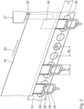
- the device 8 comprises a storage section 18 with a conveyor rail 19, which enables the transport bags 3 to be stored in the area of the storage section 18.
- Each transport bag 3 is attached to a hanging adapter 24.
- the hanging adapters 24 can be moved along the conveyor rail 19.
- the transport bags 3 are conveyed individually and hanging along the conveyor rail 19.
- the conveyor rail 19 is arranged at an angle of inclination n relative to the horizontal 20.
- the angle of inclination n is in particular between 1° and 10°.
- the transport bags 3 are conveyed automatically along the conveyor rail 19 due to the inclination due to gravity.
- the conveyor rail 19 can also have a Fig. 2 conveyor drive not shown in order to actively, i.e. driven, convey the transport pockets 3 along the conveyor rail 19.
- a build-up of the transport pockets 3 on the accumulation section 18 is ensured by a separation unit 21, which has a first stop element 22.
- the first stop element 22 is arranged at a downstream end of the conveyor rail 19, in particular at the transition of the conveyor rail 19 to the conveyor system 9.
- the first stop element 22 is oriented in particular transversely and in particular perpendicularly to a conveying direction 23 predetermined by the conveyor rail 19.
- the first stop element 22 is arranged in a direction transversely and in particular perpendicularly to the conveying direction 23 relative to the conveyor rail 19.
- the first stop element 22 In the Fig. 2 In the arrangement shown, the first stop element 22 is in a blocking position. In the blocking position, the first stop element 22 is arranged such that a hanging adapter 24 adjacent to the first stop element 22 is blocked on the conveyor rail 19. The conveyance of the hanging adapter 24 along the conveyor rail 19 is blocked by the first stop element 22.
- the separating unit 21 has a second stop element 25, which is designed to be essentially identical to the first stop element 22.
- the second stop element 25 is arranged, analogously to the first stop element 22, transversely and in particular perpendicularly with respect to the conveying direction 23 on the conveyor rail 19 and can be displaced along a direction transversely and in particular perpendicularly with respect to the conveying direction 23 with respect to the conveyor rail 19.
- the second stop element 25 is arranged in the transition area from the conveyor rail 19 to the conveyor system 9 on the device.
- the second stop element 25 is arranged downstream with respect to the conveying direction 23.
- the second stop element 25 is arranged with respect to the first stop element 22 at a distance along the conveying direction 23.
- the distance between the stop elements 22, 25 is at least large enough that a hanging adapter 24 can be arranged between the two stop elements 22, 25 on the conveyor rail 19.
- the distance between the stop elements 22, 25 can also be selected to be large enough that several hanging adapters 24 can be arranged between the stop elements 22, 25, in particular at least two, in particular at least three, in particular at least four or more hanging adapters 24.
- the separation unit 21 can also have a rotatable spindle with a screw thread, whereby there is only one transport pocket 3 in each screw thread. By rotating the spindle, the transport pockets 3 are fed individually into the conveyor system 9.
- a detection unit 26 is arranged on the conveyor rail 19.
- the detection unit 26 serves to detect the number of hanging adapters 24 within a detection area 27 of the detection unit 26.
- the detection area 27 is arranged on the conveyor rail 19 and extends in particular along the conveyor rail 19.
- the detection unit 26 is in signal connection with a control unit 28.
- the control unit 28 is designed to determine a transport distance d T for conveying the transport bags 3 by means of the conveyor system 9.
- the signal connection between the detection unit 26 and the control unit 28 is in Fig.2 schematically indicated as a cable connection.
- the signal connection can also be wireless, in particular by means of a radio connection and in particular by means of a Bluetooth connection.
- the control unit 28 is also in signal connection, in particular via a cable, with the separation unit 21.
- the detection unit 26 comprises several detection sensors 29, sixteen according to the embodiment shown. More or fewer than sixteen detection sensors 29 can also be provided in the detection unit 26.
- the detection sensors 29 are arranged along the conveyor rail 19 in a line grid.
- the line grid has a grid direction 30 that is oriented parallel to the conveying direction 23 of the conveyor rail 19.
- the detection sensors 29 are arranged along the grid direction 30 with a grid spacing ds, in particular an identical one, from one another.
- the grid spacing ds is oriented along the horizontal 20.
- the resolution accuracy of the detection unit 26 is determined by the grid spacing ds.
- the grid spacing ds is in particular defined such that a hanging adapter 24, which is arranged at any point within the detection area 27, is reliably detected by a detection sensor 29.
- the hanging adapters have an adapter width b A along the conveying direction 23. In particular, the following applies: d S ⁇ b A .
- the detection sensors 29 have a sensor surface which is circular in the embodiment shown.
- the sensor surface can also have a non-circular shape, in particular a rectangular or square shape.
- the detection area has a horizontal extension oriented along the horizontal 20, which according to the circular design of the embodiment has a diameter d F.
- the center distance of the sensor areas is defined as the grid spacing ds. In particular, the following applies: d S > d F .
- the number of detection sensors 29, the grid spacing ds and the inclination angle n result in a length L E of the detection area 27.
- the length L E is oriented along the conveying direction 23.
- the detection unit 26 is arranged with respect to the conveyor rail 19 and in particular is fastened to the conveyor rail 19 such that the grid direction 30 runs at a vertical distance dv below a lower end 31 of the conveyor rail 19.
- the detection unit 26 is arranged such that the detection sensors 29 reliably detect the hanging adapters 24 protruding downwards from the conveyor rail 19.
- the detection sensors 29 are designed as light barriers with a transmitting element and a receiving element.
- the transmitting element sends out an optical signal that is received by the corresponding receiving element. If no optical signal is received, this means that an object, i.e. a hanging adapter 24, is arranged between the transmitting element and the receiving element.
- the detection sensor 29 can be designed with a transmitting/receiving element and a reflection element.
- the transmitting/receiving element sends an optical signal to the reflection element, which is then reflected back to the transmitting/receiving element. Accordingly, a hanging adapter 24 is detected here if no reflected signal is detected by the transmitting/receiving element.
- the detection sensors 29, i.e. the transmitting elements and receiving elements or the transmitting/receiving elements and the reflection elements, are arranged in pairs on both sides of the conveyor rail 19.
- the hanging adapters 24 are conveyed along the conveyor rail 19 between the detection sensors 29 arranged in pairs.
- the detection sensors 29 form a so-called light grid.
- the conveyor technology 9 of the overhead conveyor system 1 has the conveyor rail 19, which can be laid in a room by means of a suitable support device.
- a conveyor means 32 in the form of a conveyor chain is arranged in the conveyor rail 19, which is designed as a hollow box profile, and can be driven along the conveying direction 23 by means of drive means (not shown).
- the hanging adapters 24 are also shown, which can be moved in the conveyor rail 19 by means of the conveyor means 32.
- the conveyor chain 32 is a so-called roller chain, which has rollers 33 that are pivotally connected to one another at a roller distance a from one another by means of connecting plates 34 and bolts 35.
- the bolts 35 have bolt-shaped extensions that protrude downward and serve as drivers 36.
- the bolts 35 with the drivers 36 run perpendicular to the conveyor rail 19 in a vertical plane spanned by the conveying direction 23.
- a center distance between adjacent drivers 36 in the conveyor rail 19 in the conveying direction 23 corresponds exactly to the pitch of the conveyor chain 32, i.e. the roller distance a, and is therefore unchangeable and constant.
- the center distance between adjacent drivers 36 corresponds to a regular driver distance d A .
- the conveyor rail 19 On its underside, the conveyor rail 19 has a longitudinal slot 37 extending in the conveying direction 23. A flat support part 38 of each hanging adapter 24 protrudes downwards from the conveyor rail 19 through the longitudinal slot 37. In its upper area, the hanging adapter 24 has a roller 39 on each side of the support part 38, which are each supported on a guide web of the conveyor rail (not shown in detail) and can be moved in the conveying direction 23. There are therefore only a few common rollers 39, which can be rotated about a common axis 40. The entire hanging adapter 24 can swing around the axis 40 in the conveyor rail 19.
- the support part 38 has a receiving opening 41 at its lower end, into which a hook 42 of the transport bag 3 can be hooked.
- a hook 42 of a coat hanger can also be hooked into the receiving opening 41.
- An identification element 43 which can be a transponder, a bar code or a QR code, is arranged on the hanging adapter 24 between the receiving opening 41 and the underside of the conveyor rail 19.
- the identification device 38 runs in the conveying direction 23 in accordance with the arrangement of the plate-like support part 38, i.e. its main surface is open transversely to the conveying direction 23, i.e. to the side.
- an identification device such as a barcode reader or a transponder reader.
- a stem-like extension 44 of the hanging adapter 24 extends above the rollers 39 and is formed in one piece with the support part 38 at its upper end.
- a stop 45 in the form of a crossbar is formed at the upper end of the extension 44.
- the extension 44 and the stop 45 have the basic shape of a hammer.
- the hanging adapter 24 is arranged with the extension 44 and the stop 45 in a space 46 formed between two adjacent drivers 36.
- the individual items 2 each have an individual item identification device by means of which the individual items 2 can be clearly identified. In the case of items of clothing, this can be done, for example, based on the manufacturer, the article, the size and/or the color.
- the identification data of the individual items 2 can be transmitted to a central control unit 47 using signals and linked to the data stored in the identification element 38 of a hanging adapter 24.
- the individual items 2 can be clearly assigned during their transport in the hanging conveyor system 1 using appropriately arranged reading devices along the hanging conveyor system 1, which in particular record the position of the transport bags 3. This makes it possible to transport the individual items 2 along the hanging conveyor system in a targeted manner.
- Individual goods 2 are fed to the goods receiving area 6 and from there are conveyed either directly or via the goods warehouse 5 to the loading station 7, where a transport bag 3 is loaded with, in particular, a single individual item 2.
- the transport bags 3 loaded with individual goods 2 are conveyed from the loading station 7 to the device 8 and accumulated on the accumulation section 18.
- the transport bags 3 arranged in a stacked manner on the stacking section 18 form a sample 48 of transport bags 3.
- the number of hanging adapters 24 in the detection area 27 is recorded by means of the detection unit 26.
- the number of hanging adapters 24 recorded, according to Fig.2 for example five, is transmitted to the control unit 28.
- the accumulation length Ls of the accumulated transport bags 3 is transmitted to the control unit 28 by the detection unit 26.
- the accumulation length Ls is understood to be the extension along the conveyor rail 19 in which the hanging adapters 24 are located. According to the embodiment shown, the accumulation length Ls is smaller than the longitudinal extension L E of the detection area 27.
- the accumulation length Ls is smaller than or equal to the length L E of the detection area 27.
- a transport distance d T is variably set depending on the average adapter distance d m , with which the transport pockets 3 are placed in the conveyor system 9 of the overhead conveyor system 1.
- the transport distance d T is set in such a way that the transport pockets 3 are conveyed in the conveyor system 9 with a distance from one another.
- the transport pockets 3 typically do not touch one another.
- the transport distance d T is provided with a safety factor s F.
- the safety factor s F is in particular between 1.2 and 5, in particular between 1.5 and 3 and in particular between 2 and 3.
- the transport bags 3 are placed into the conveyor system 9 by the first stop element 22 being moved away from the Fig. 2 shown blocking position into a release position.
- the first stop element 22 can be actuated by means of the separating unit 21 along the actuating direction 49. Due to the inclination of the accumulation section 18, the transport bag 3, which is adjacent to the first stop element 22 is arranged, past it and is stopped at the second stop element 25, which is in the blocking position. The first stop element 22 is then moved back into the blocking position. This prevents another transport bag 3 from getting between the two stop elements 22, 25.
- only a single hanging adapter 24 is arranged between the two stop elements 22, 25.
- the second stop element 25 opens and places the transport bag 3 individually into the conveyor system 9.
- the transport bag 3, in particular the corresponding hanging adapter 24, is carried along by one of the carriers 36.
- the respective transport distance d T results from the time interval ⁇ t and the speed of the conveyor 32 in the conveyor system 9.
- the transport pockets 3 have different thicknesses depending on the individual goods 2 being conveyed, which results in different adapter distances and thus a different average adapter distance d m .
- Different transport distances d T,1 , d T,2 are defined accordingly.
- the time interval ⁇ t is in particular determined in such a way that the hanging adapter 24 to be fed into the conveyor system 9 is carried along by a selected carrier 36.
- variable determination of the transport distances d T is particularly uncomplicated and reliable.
- the transport bags 3 are conveyed along the conveyor system 9 with an optimal transport distance d T.
- the respective transport distance d T,i between two adjacent transport bags 3 is individually adjusted.
- the respective transport distance d T,i is set in such a way that a collision between adjacent transport pockets 3 and thus a disruption of the overhead conveyor system 1 is avoided.
- the transport distance d T is also small enough to ensure the greatest possible utilization of the conveying capacity of the overhead conveyor system 1.
- the detection unit 26 detects the average distances d m of all transport bags 3 in the accumulation section 18, transmits them to the control unit 28, and from there the separation unit 21 is controlled accordingly.
- the control unit 28 is designed in particular as a programmable logic controller and enables an evaluation of the values transmitted by the detection unit 26 for the accumulation length Ls and the number N A of hanging adapters 24. It is advantageous to take historical data into account when determining the transport distances d T , in particular the data of hanging adapters, i.e. their number and their accumulation length Ls, which were in the detection area 27 in a previous period. This historical data can in particular be combined with currently recorded data.
- the historical data includes such small average adapter distances d m that it would have been possible to specify a transport distance d T that is smaller than a required minimum transport distance. Because the minimum transport distance cannot be undercut for technical reasons, very thin overhead goods were fed in with a transport distance d T that was larger than would have been necessary. This results in a comparatively reduced conveying density, which can be taken into account when determining the transport distance d T on the basis of current data. In particular, this is taken into account in such a way that a transport distance d T for a current transport bag 3 can be selected or specified to be smaller than would be required according to an allocation rule used to determine the transport distance d T.
- the transport distances d T can be set smaller than would be necessary based on the specification, since the new goods 4 previously fed into the conveyor system were fed in at a low conveying density.
- the consideration of historical data is particularly possible as long as an excess of gaps resulting from the very thin overhead goods 4 is used up by the thicker overhead goods 4.
- the conveying capacity can be increased even further.
- the system-specific minimum transport distance must also be observed when compensating for the excess of gaps.
- the historical data of the adapter distances d m can be used to determine and/or calculate an exact fill level of a delivery or storage section.
- storage units for overhead conveying goods 4 can be filled more efficiently, since a blanket assumption of an average thickness for all overhead conveying goods 4 is unnecessary.
- the design of a delivery section of the conveyor system 9 can be improved.
- the current, individually determined transport distance d T can be used for the design.
- a design of the delivery section based on a maximum thickness of the overhead conveyor goods is unnecessary. This means that the delivery lines can be filled more efficiently, especially with a higher density of goods. The risk of overfilling a delivery line is prevented. The space required for the delivery line is increased. The investment costs for such an overhead conveyor system are reduced.
- the overhead goods 4 placed in the conveyor system 9 are fed to the goods storage 10, the sorting unit 11 and the unloading station 12. There, the individual goods 2 are emptied from the transport bag 3, packed into orders 15 at packing stations 14 and delivered from the goods exit 16. The emptied transport bags 3 are returned to the loading station 7 via the return line 13. It is also conceivable that the conveyor system 9 has branch lines (not shown) in order to convey the overhead goods 4 directly past the goods storage 10 and/or the sorting unit 11.
Landscapes
- Engineering & Computer Science (AREA)
- Mechanical Engineering (AREA)
- Control Of Conveyors (AREA)
- Chain Conveyers (AREA)
Claims (12)
- Dispositif pour introduire des sacs de transport (3) dans une technique de transport (9) d'une installation de transport suspendu (1) comprenanta. un rail de transport (19) pouvant être couplé par technique de transport à la technique de transport (9), le long duquel les sacs de transport (3) peuvent être transportées en étant suspendues respectivement au moyen d'un adaptateur de suspension (24),b. une unité de détection (26) pour détecter le nombre d'adaptateurs de suspension (24) disposés à l'intérieur d'une zone de détection (27) sur le rail de transport (19),c. une unité de commande (28) qui est en liaison de signalisation avec l'unité de détection (26) et qui est conçue pour fixer de manière variable une distance de transport (dT) pour le transport des sacs de transport (3) au moyen de la technique de transport (9),d. une unité de séparation (21) en liaison de signalisation avec l'unité de commande (28) pour l'introduction individuelle des adaptateurs de suspension (24) dans la technique de transport (9) avec la distance de transport (dT) fixée de manière variable,caractérisé en ce que l'unité de commande (28) est conçue pour déterminer, à l'aide du nombre d'adaptateurs de suspension (24), une distance moyenne (dm) d'adaptateurs de suspension (24) voisins, à l'aide de laquelle la distance de transport (dT) est déterminée de manière variable.
- Dispositif selon la revendication 1, caractérisé en ce que l'unité de détection (26) présente au moins un capteur de détection (29) pour détecter, en particulier sans contact, un adaptateur de suspension (24).
- Dispositif selon la revendication 2, caractérisé en ce que ledit au moins un capteur de détection (29) est réalisé sous la forme d'un capteur optique, en particulier d'une barrière lumineuse, ou d'un capteur RFID.
- Dispositif selon la revendication 2 ou 3, caractérisé par plusieurs des capteurs de détection (29) qui sont disposés le long du rail de transport (19) selon une grille de lignes.
- Dispositif selon l'une quelconque des revendications précédentes, caractérisé en ce que l'unité de séparation (21) présente un élément d'arrêt commutable (22, 25) qui peut être commuté entre une position de blocage, dans laquelle l'adaptateur de suspension (24) voisin de l'élément d'arrêt (22, 25) est bloqué sur le rail de transport (19), et une position de libération, dans laquelle l'adaptateur de suspension (24) voisin de l'élément d'arrêt (22, 25) est libéré pour le transport depuis le rail de transport (19) dans la technique de transport (9).
- Dispositif selon la revendication 5, caractérisé en ce que l'élément d'arrêt (22, 25) est disposé sur le rail de transport (19), en particulier est fixé sur le rail de transport (19).
- Installation de transport suspendu (1) comprenanta. un dispositif (8) selon l'une quelconque des revendications précédentes,b. une technique de transport (9) reliée au dispositif (8) par une technique de transport pour l'entraînement des adaptateurs de suspension (24) introduits.
- Installation de transport suspendu selon la revendication 7, caractérisée en ce que la technique de transport (9) présente un moyen de transport (27) avec des entraîneurs (36) qui y sont fixés.
- Installation de transport suspendu selon la revendication 8, caractérisée en ce que les entraîneurs (36) sont disposés le long du moyen de transport (27) avec une distance d'entraîneurs (dA), en particulier régulière.
- Installation de transport suspendu selon la revendication 9, caractérisée en ce que la distance d'entraîneurs (dA) est supérieure à une longueur (LH) des adaptateurs de suspension (24) orientée le long de la direction de transport (23).
- Procédé pour introduire des sacs de transport (3) dans une technique de transport (9) d'une installation de transport suspendu (1) comprenant les étapes de procédé suivantes- transport suspendu d'adaptateurs de suspension (24) portant chacun un sac de transport (3) le long d'un rail de transport (19) qui peut être couplé à la technique de transport (9) par une technique de transport,- détection du nombre d'adaptateurs de suspension (24) disposés à l'intérieur d'une zone de détection (27) sur le rail de transport (19) au moyen d'une unité de détection (26),- fixation de manière modifiable d'une distance de transport (dT) pour le transport des sacs de transport (3) avec la technique de transport (9) au moyen d'une unité de commande (28) en liaison de signalisation avec l'unité de détection (26),- introduction individuelle des adaptateurs de suspension (24) dans la technique de transport (9) avec la distance de transport (dT) fixée de manière variable au moyen d'une unité de séparation (21) en liaison de signalisation avec l'unité de commande (28),caractérisé en ce qu'à l'aide du nombre d'adaptateurs de suspension (24), une distance moyenne (dm) d'adaptateurs de suspension (24) voisins est déterminée, à l'aide de laquelle la distance de transport (dT) est fixée de manière variable.
- Procédé selon la revendication 11, caractérisé en ce que l'introduction individuelle des adaptateurs de suspension (24) est réalisée par la commutation d'un élément d'arrêt commutable (22, 25) de l'unité de séparation (21) d'une position de blocage, dans laquelle l'adaptateur de suspension (24) voisin de l'élément d'arrêt (22, 25) est bloqué sur le rail de transport (19), dans une position de libération dans laquelle l'adaptateur de suspension (24) voisin de l'élément d'arrêt (22, 25) est libéré pour le transport depuis le rail de transport (19) dans la technique de transport (9).
Applications Claiming Priority (2)
| Application Number | Priority Date | Filing Date | Title |
|---|---|---|---|
| DE102019215304.6A DE102019215304B3 (de) | 2019-10-04 | 2019-10-04 | Vorrichtung und Verfahren zum Aufgeben von Hängefördergut in eine Hängeförderanlage sowie Hängeförderanlage mit einer derartigen Vorrichtung |
| DE102020214613.6A DE102020214613B4 (de) | 2019-10-04 | 2020-11-19 | Vorrichtung und Verfahren zum Aufgeben von Transporttaschen in eine Fördertechnik einer Hängeförderanlage sowie derartige Hängeförderanlage |
Publications (2)
| Publication Number | Publication Date |
|---|---|
| EP4001180A1 EP4001180A1 (fr) | 2022-05-25 |
| EP4001180B1 true EP4001180B1 (fr) | 2024-08-21 |
Family
ID=71105289
Family Applications (2)
| Application Number | Title | Priority Date | Filing Date |
|---|---|---|---|
| EP20180362.4A Active EP3800146B1 (fr) | 2019-10-04 | 2020-06-16 | Dispositif et procédé de libération de la marchandise transportée suspendue dans une installation de transport suspendu ainsi qu'installation de transport suspendu dotée d'un tel dispositif |
| EP21207748.1A Active EP4001180B1 (fr) | 2019-10-04 | 2021-11-11 | Dispositif et procédé de distribution de sacs de transport dans une technique de transport d'une installation de transport suspendu, ainsi qu'une telle installation de transport suspendu |
Family Applications Before (1)
| Application Number | Title | Priority Date | Filing Date |
|---|---|---|---|
| EP20180362.4A Active EP3800146B1 (fr) | 2019-10-04 | 2020-06-16 | Dispositif et procédé de libération de la marchandise transportée suspendue dans une installation de transport suspendu ainsi qu'installation de transport suspendu dotée d'un tel dispositif |
Country Status (4)
| Country | Link |
|---|---|
| US (2) | US11383938B2 (fr) |
| EP (2) | EP3800146B1 (fr) |
| DE (2) | DE102019215304B3 (fr) |
| ES (2) | ES2928628T3 (fr) |
Families Citing this family (16)
| Publication number | Priority date | Publication date | Assignee | Title |
|---|---|---|---|---|
| DE102019215304B3 (de) | 2019-10-04 | 2020-08-13 | Dürkopp Fördertechnik GmbH | Vorrichtung und Verfahren zum Aufgeben von Hängefördergut in eine Hängeförderanlage sowie Hängeförderanlage mit einer derartigen Vorrichtung |
| DE102021110132A1 (de) | 2021-04-21 | 2022-10-27 | Dematic Logistics Gmbh | Verfahren zum Betreiben eines Förderers für hintereinander folgende Güter und entsprechendes Fördersystem |
| CN115724090B (zh) * | 2021-08-30 | 2025-06-03 | 浙江衣拿智能科技股份有限公司 | 连接轨道、连接部以及无固定货架仓储系统 |
| DE102021211484A1 (de) * | 2021-10-12 | 2023-04-13 | Dürkopp Fördertechnik GmbH | Verfahren und Anlage zum Kommissionieren und Packen von hängend geförderten Einzelwaren |
| DE102021211571A1 (de) * | 2021-10-13 | 2023-04-13 | Dürkopp Fördertechnik GmbH | Hängefördertechnik und Verfahren zum Fördern von Hängeadaptern sowie Hängeförderanlage mit einer derartigen Hängefördertechnik |
| DE102021129341B3 (de) * | 2021-11-11 | 2022-08-18 | Koenig & Bauer Ag | Produktionslinie zur Bearbeitung von Blechtafeln |
| DE102022103810A1 (de) * | 2022-02-17 | 2023-08-17 | Dematic Gmbh | Profilverbinder für Hängeförderanlage |
| DE102022205209A1 (de) | 2022-05-24 | 2023-11-30 | Dürkopp Fördertechnik GmbH | Fördervorrichtung und Förderverfahren für Waren |
| EP4389653A1 (fr) * | 2022-12-22 | 2024-06-26 | BEUMER Group GmbH & Co. KG | Station d'essai de support, convoyeur suspendu et procédé de vérification d'un support |
| DE102023000184A1 (de) | 2023-01-19 | 2024-07-25 | Emhs Gmbh | Generieren von Daten beim Übergeben von autonom fahrenden Hängetaschen in ein Hängetaschenlager |
| CH720472A1 (de) | 2023-02-03 | 2024-08-15 | Ferag Ag | Abstandsoptimierungsvorrichtung für ein Fördersystem, Verfahren zur Förderung von Hängetransportelementen und Hängefördersystem |
| DE102023123292B4 (de) * | 2023-08-30 | 2026-01-22 | Ssi Schäfer Automation Gmbh (At) | Hängefördersystem und Verfahren zum Betreiben eines Hängefördersystems |
| CN117699337A (zh) * | 2024-01-05 | 2024-03-15 | 上汽通用五菱汽车股份有限公司 | 一种可变节距生产涂装积放链系统 |
| DE102024110528B3 (de) | 2024-04-15 | 2025-09-11 | Dematic Gmbh | Verfahren zum Betreiben eines Hängeförderers für hintereinander folgende Hängetransporttaschen und entsprechend eingerichtetes Warenlager |
| CN118154137B (zh) * | 2024-05-10 | 2024-08-09 | 青岛北洋天青数联智能有限公司 | 一种基于数据分析的悬挂链输送线智能控制系统 |
| DE102024123981A1 (de) * | 2024-08-22 | 2026-02-26 | Ssi Schäfer Automation Gmbh | System aus mit einem Hängeförderer kooperierenden Transport-Drohnen |
Family Cites Families (42)
| Publication number | Priority date | Publication date | Assignee | Title |
|---|---|---|---|---|
| DE9003011U1 (de) | 1990-03-12 | 1991-07-11 | Veit GmbH & Co, 8910 Landsberg | Vereinzelungsvorrichtung |
| US5072822A (en) * | 1990-06-20 | 1991-12-17 | Fabri-Check, Inc. | Article sorting system |
| DE4244219A1 (de) | 1992-12-24 | 1994-06-30 | R & W System Innovation Maschi | Fördervorrichtung zur Vereinzelung von Transporthaken |
| DE19501520C2 (de) | 1994-12-08 | 1996-09-19 | Andreas Rosenplenter | Fördervorrichtung |
| SE512991C2 (sv) * | 1995-03-21 | 2000-06-12 | Metric Interconveyor Ab | Produktbärare för användning vid interntransport och behandling av klädesplagg samt förfarande för utnyttjande av produktbäraren |
| DE19536313C2 (de) | 1995-09-29 | 2000-07-13 | Duerkopp Adler Ag | Verfahren zum Fördern von auf Bügel hängendem Fördergut und Vorrichtungen zur Verwendung in dem Verfahren |
| DE29519285U1 (de) | 1995-12-05 | 1996-02-22 | RSL Logistik GmbH & Co., 86899 Landsberg | Fördereinrichtung |
| US5738202A (en) | 1995-12-21 | 1998-04-14 | Sandvik Sorting Systems, Inc. | Methods and apparatus for establishing a desired positional relationship between random-length articles conveyed in single file |
| DE19615773C2 (de) * | 1996-04-20 | 1998-06-04 | Duerkopp Adler Ag | Verfahren zum Vereinzeln von Förderträgern |
| DE29906532U1 (de) | 1999-04-13 | 1999-08-12 | Pavel GmbH Logistiksysteme für Bekleidung, 33790 Halle | Längen-Meßeinrichtung für hängend zu verpackende Bekleidungsstücke |
| ATE264257T1 (de) | 2000-07-07 | 2004-04-15 | Ferag Ag | Verfahren und vorrichtung zur gehaltenen förderung von gegenständen auf einer förderstrecke mit pufferspeicher |
| DE10039394C1 (de) | 2000-08-11 | 2001-09-13 | Mts Modulare Transp Systeme Gm | Sortierverfahren, Sortieranlage und Sortiersystem |
| DE102005006455A1 (de) | 2005-02-12 | 2006-08-24 | Dürkopp Adler AG | Transport-System für hängende Gegenstände |
| DE502008000688D1 (de) | 2007-02-16 | 2010-07-01 | Rsl Logistik Gmbh & Co Kg | Separator und damit ausgestattete hängefördereinrichtung |
| DE102007025553A1 (de) | 2007-05-31 | 2008-12-04 | Siemens Ag | Steuervorrichtung, Sortieranlage sowie Sortierverfahren für Güter |
| US20090006533A1 (en) | 2007-06-28 | 2009-01-01 | Yahoo! Inc. | Server-aided approach to improve media negotiation efficiency |
| CA2844967C (fr) | 2007-09-07 | 2016-02-02 | Dematic Corp. | Convoyeurs |
| DE102008061685A1 (de) * | 2008-12-11 | 2010-06-17 | Dürkopp Adler AG | Belade-Station für in einer Hänge-Förder-Anlage transportierte Transport-Taschen |
| WO2011025942A1 (fr) | 2009-08-28 | 2011-03-03 | Dematic Corp. | Admission de transporteur |
| DE102010010107A1 (de) | 2010-03-04 | 2011-09-08 | Dürkopp Fördertechnik GmbH | Förderanlage für hängende Gegenstände |
| DE102010053590B4 (de) * | 2010-12-06 | 2019-03-07 | Dürkopp Fördertechnik GmbH | Tragetasche für Fördergut und Förderanlage für eine Tragetasche |
| DE102011101987A1 (de) | 2011-05-17 | 2012-11-22 | SSI Schäfer PEEM GmbH | Förderanlage und Transporttasche für eine Förderanlage sowie Verfahren zur Beförderung eines Fördergutes |
| DE102011104511C5 (de) | 2011-06-15 | 2024-05-16 | Ssi Schäfer Automation Gmbh | Distributionslager und Verfahren zum auftragsorientierten Zusammenstellen von verschiedenen Artikeln mit einem reduzierten Puffer |
| DE102011116086A1 (de) | 2011-10-12 | 2013-04-18 | SSI Schäfer PEEM GmbH | Staudruckminderer sowie Förderanlage mit einem Staudruckminderer |
| DE102011118303B4 (de) * | 2011-11-08 | 2017-12-14 | Ssi Schäfer Automation Gmbh | Förderanlage mit einer Förderkette und Tragsegment für einen Förderträger einer Förderkette |
| DE102012205735A1 (de) * | 2012-04-05 | 2013-10-10 | Dürkopp Fördertechnik GmbH | Staustrecke für eine Förderanlage sowie derartige Förderanlage |
| CH707799A1 (de) * | 2013-03-28 | 2014-09-30 | Ferag Ag | Verfahren und Einrichtung zum Übergeben von Stückgütern an eine Förderanlage. |
| PL2886494T3 (pl) | 2013-12-23 | 2017-09-29 | Dematic Logistics Gmbh | Urządzenie przenośnikowe do transportowania wiszących przedmiotów |
| DE102014201301A1 (de) * | 2014-01-24 | 2015-07-30 | Dürkopp Fördertechnik GmbH | Fördervorrichtung und Verfahren zum automatisierten Fördern von Einzelwaren |
| DE102014203239A1 (de) | 2014-02-24 | 2015-08-27 | Dürkopp Fördertechnik GmbH | Transportsystem und Verfahren zum Transportieren von Hängeartikeln |
| DE102014205545B4 (de) * | 2014-03-25 | 2018-03-22 | Dürkopp Fördertechnik GmbH | Vorrichtung und Verfahren zum platzsparenden Anordnen von Hängewaren |
| DE102014010862B4 (de) * | 2014-07-25 | 2021-01-07 | Khs Corpoplast Gmbh | Verfahren und Vorrichtung zum Transport von Vorformlingen |
| CH710856A1 (de) | 2015-03-02 | 2016-09-15 | Ferag Ag | Transporteinheit einer Hängefördervorrichtung mit einem Pufferelement. |
| EP3380416B1 (fr) * | 2015-11-25 | 2022-07-20 | Ferag AG | Sac de transport et procédé de remplissage et de vidage d'un tel sac de transport |
| DE102016208866A1 (de) * | 2016-05-23 | 2017-11-23 | Rsl Logistik Gmbh & Co. Kg | Fördergutübergabestation sowie eine damit ausgestattete Hängefördereinrichtung |
| DE102016110898B3 (de) | 2016-06-14 | 2017-06-29 | Nordischer Maschinenbau Rud. Baader Gmbh + Co. Kg | Transportstation und Verfahren zum Transportieren von Fischen quer zu ihrer Längserstreckung in Transportrichtung sowie Fischverarbeitungsmaschine mit einer solchen Transportstation |
| EP3315433B1 (fr) | 2016-11-01 | 2020-07-15 | Ferag AG | Dispositif de transmission pour support de produits doté des moyens de retenue |
| EP3395451A1 (fr) * | 2017-04-24 | 2018-10-31 | Siemens Aktiengesellschaft | Dispositif de communication et procédé de transfert de marchandises au détail |
| US10532841B2 (en) * | 2017-05-24 | 2020-01-14 | Toyo Jidoki Co., Ltd. | Method and apparatus of supplying a bag |
| CH714004A1 (de) | 2017-07-20 | 2019-01-31 | Ferag Ag | Kommissionieranlage zum Kommissionieren von unterschiedlichen, insbesondere hängend transportierbaren Waren, sowie Verfahren zum Betrieb einer solchen Kommissionieranlage. |
| CH714814A1 (de) * | 2018-03-20 | 2019-09-30 | Ferag Ag | Fördervorrichtung zum Eintakten von Transporteinheiten. |
| DE102019215304B3 (de) * | 2019-10-04 | 2020-08-13 | Dürkopp Fördertechnik GmbH | Vorrichtung und Verfahren zum Aufgeben von Hängefördergut in eine Hängeförderanlage sowie Hängeförderanlage mit einer derartigen Vorrichtung |
-
2019
- 2019-10-04 DE DE102019215304.6A patent/DE102019215304B3/de active Active
-
2020
- 2020-06-16 ES ES20180362T patent/ES2928628T3/es active Active
- 2020-06-16 EP EP20180362.4A patent/EP3800146B1/fr active Active
- 2020-06-25 US US16/912,332 patent/US11383938B2/en active Active
- 2020-11-19 DE DE102020214613.6A patent/DE102020214613B4/de active Active
-
2021
- 2021-11-11 ES ES21207748T patent/ES2988294T3/es active Active
- 2021-11-11 EP EP21207748.1A patent/EP4001180B1/fr active Active
- 2021-11-18 US US17/529,959 patent/US11926487B2/en active Active
Also Published As
| Publication number | Publication date |
|---|---|
| DE102019215304B3 (de) | 2020-08-13 |
| DE102020214613B4 (de) | 2026-03-12 |
| DE102020214613A1 (de) | 2021-12-16 |
| ES2928628T3 (es) | 2022-11-21 |
| ES2988294T3 (es) | 2024-11-20 |
| US20220153533A1 (en) | 2022-05-19 |
| EP3800146B1 (fr) | 2022-09-21 |
| US11926487B2 (en) | 2024-03-12 |
| US11383938B2 (en) | 2022-07-12 |
| EP3800146A1 (fr) | 2021-04-07 |
| US20210101756A1 (en) | 2021-04-08 |
| EP4001180A1 (fr) | 2022-05-25 |
Similar Documents
| Publication | Publication Date | Title |
|---|---|---|
| EP4001180B1 (fr) | Dispositif et procédé de distribution de sacs de transport dans une technique de transport d'une installation de transport suspendu, ainsi qu'une telle installation de transport suspendu | |
| EP3581523B1 (fr) | Dispositif et procédé de mise à disposition, en fonction de la demande, de marchandises individuelles pour plusieurs demandes sur un poste d'emballage | |
| EP3254893B1 (fr) | Véhicule de livraison et procédé de livraison d'envois à différents endroits le long d'un itinéraire | |
| AT501896A4 (de) | Kommissionierverfahren sowie kommissionierfördervorrichtung für ein lager | |
| EP2855282B1 (fr) | Procédé et appareil pour transférer des articles à partir de stations de distribution vers des stations de réception | |
| DE19927251A1 (de) | Vorrichtung zum Handhaben von Stückgütern | |
| EP3437745B1 (fr) | Trieur matriciel | |
| EP2923974B1 (fr) | Dispositif et procédé d'agencement peu encombrant de marchandises suspendues | |
| EP4541733A1 (fr) | Procédé et station de transfert pour comprimer un flux de marchandises dans une installation de transport suspendu | |
| AT520860A1 (de) | Kommissioniersystem zum Lagern und Kommissionieren von Packeinheiten sowie Ladungsträger für die Packeinheiten | |
| AT501897A4 (de) | Verfahren und vorrichtung zum automatischen beschicken einer warenausgabeeinrichtung | |
| EP4166482B1 (fr) | Technique de transport suspendu et procédé de transport des adaptateurs de suspension, ainsi qu'installation de transport suspendu dotée d'une telle technique de transport suspendu | |
| DE10033281A1 (de) | Arbeitsverfahren und Vorrichtung zum Kommissionieren von Stückgut | |
| DE102004012043A1 (de) | Vorrichtung und Verfahren zum lagegerechten Übergeben von quaderförmigen Waren | |
| WO2011051332A1 (fr) | Dispositif de préparation de commande automatisée et procédé de préparation de commande automatisée de livres, articles de presse, imprimés et objets similaires | |
| EP4282790A1 (fr) | Procédé et dispositif de transport pour marchandises de plusieurs travaux | |
| DE102023123292B4 (de) | Hängefördersystem und Verfahren zum Betreiben eines Hängefördersystems | |
| EP3084733B1 (fr) | Procédé et dispositif de traitement de documents de valeur | |
| AT511598B1 (de) | Automatisiertes warenumschlaglager | |
| EP4282786B1 (fr) | Dispositif et procédé de transport de marchandises | |
| EP4166480B1 (fr) | Dispositif et procédé de transport suspendu d'objets | |
| EP4058996B1 (fr) | Ensemble et procédé de traitement de documents de valeur | |
| EP1245514B1 (fr) | Dispositif de stockage et de distribution pour des éléments de transport | |
| DE102009043084B4 (de) | Anlage zum Zuführen und Lagern von Reifen auf Paletten | |
| DE1277130B (de) | Vorrichtung zum Zusammentragen von Gegenstaenden |
Legal Events
| Date | Code | Title | Description |
|---|---|---|---|
| PUAI | Public reference made under article 153(3) epc to a published international application that has entered the european phase |
Free format text: ORIGINAL CODE: 0009012 |
|
| STAA | Information on the status of an ep patent application or granted ep patent |
Free format text: STATUS: THE APPLICATION HAS BEEN PUBLISHED |
|
| AK | Designated contracting states |
Kind code of ref document: A1 Designated state(s): AL AT BE BG CH CY CZ DE DK EE ES FI FR GB GR HR HU IE IS IT LI LT LU LV MC MK MT NL NO PL PT RO RS SE SI SK SM TR |
|
| STAA | Information on the status of an ep patent application or granted ep patent |
Free format text: STATUS: REQUEST FOR EXAMINATION WAS MADE |
|
| 17P | Request for examination filed |
Effective date: 20220622 |
|
| RBV | Designated contracting states (corrected) |
Designated state(s): AL AT BE BG CH CY CZ DE DK EE ES FI FR GB GR HR HU IE IS IT LI LT LU LV MC MK MT NL NO PL PT RO RS SE SI SK SM TR |
|
| REG | Reference to a national code |
Ref legal event code: R079 Ipc: B65G0043080000 Ref country code: DE Ref legal event code: R079 Ref document number: 502021004848 Country of ref document: DE Free format text: PREVIOUS MAIN CLASS: B65G0017200000 Ipc: B65G0043080000 |
|
| RIC1 | Information provided on ipc code assigned before grant |
Ipc: B65G 17/20 20060101ALI20240404BHEP Ipc: B65G 47/61 20060101ALI20240404BHEP Ipc: B65G 43/08 20060101AFI20240404BHEP |
|
| GRAP | Despatch of communication of intention to grant a patent |
Free format text: ORIGINAL CODE: EPIDOSNIGR1 |
|
| STAA | Information on the status of an ep patent application or granted ep patent |
Free format text: STATUS: GRANT OF PATENT IS INTENDED |
|
| INTG | Intention to grant announced |
Effective date: 20240521 |
|
| GRAS | Grant fee paid |
Free format text: ORIGINAL CODE: EPIDOSNIGR3 |
|
| GRAA | (expected) grant |
Free format text: ORIGINAL CODE: 0009210 |
|
| STAA | Information on the status of an ep patent application or granted ep patent |
Free format text: STATUS: THE PATENT HAS BEEN GRANTED |
|
| AK | Designated contracting states |
Kind code of ref document: B1 Designated state(s): AL AT BE BG CH CY CZ DE DK EE ES FI FR GB GR HR HU IE IS IT LI LT LU LV MC MK MT NL NO PL PT RO RS SE SI SK SM TR |
|
| REG | Reference to a national code |
Ref country code: GB Ref legal event code: FG4D Free format text: NOT ENGLISH |
|
| REG | Reference to a national code |
Ref country code: CH Ref legal event code: EP |
|
| P01 | Opt-out of the competence of the unified patent court (upc) registered |
Free format text: CASE NUMBER: APP_45764/2024 Effective date: 20240807 |
|
| REG | Reference to a national code |
Ref country code: IE Ref legal event code: FG4D Free format text: LANGUAGE OF EP DOCUMENT: GERMAN Ref country code: NL Ref legal event code: FP |
|
| REG | Reference to a national code |
Ref country code: DE Ref legal event code: R096 Ref document number: 502021004848 Country of ref document: DE |
|
| REG | Reference to a national code |
Ref country code: ES Ref legal event code: FG2A Ref document number: 2988294 Country of ref document: ES Kind code of ref document: T3 Effective date: 20241120 |
|
| REG | Reference to a national code |
Ref country code: LT Ref legal event code: MG9D |
|
| PG25 | Lapsed in a contracting state [announced via postgrant information from national office to epo] |
Ref country code: NO Free format text: LAPSE BECAUSE OF FAILURE TO SUBMIT A TRANSLATION OF THE DESCRIPTION OR TO PAY THE FEE WITHIN THE PRESCRIBED TIME-LIMIT Effective date: 20241121 |
|
| PG25 | Lapsed in a contracting state [announced via postgrant information from national office to epo] |
Ref country code: GR Free format text: LAPSE BECAUSE OF FAILURE TO SUBMIT A TRANSLATION OF THE DESCRIPTION OR TO PAY THE FEE WITHIN THE PRESCRIBED TIME-LIMIT Effective date: 20241122 Ref country code: PL Free format text: LAPSE BECAUSE OF FAILURE TO SUBMIT A TRANSLATION OF THE DESCRIPTION OR TO PAY THE FEE WITHIN THE PRESCRIBED TIME-LIMIT Effective date: 20240821 Ref country code: FI Free format text: LAPSE BECAUSE OF FAILURE TO SUBMIT A TRANSLATION OF THE DESCRIPTION OR TO PAY THE FEE WITHIN THE PRESCRIBED TIME-LIMIT Effective date: 20240821 Ref country code: PT Free format text: LAPSE BECAUSE OF FAILURE TO SUBMIT A TRANSLATION OF THE DESCRIPTION OR TO PAY THE FEE WITHIN THE PRESCRIBED TIME-LIMIT Effective date: 20241223 |
|
| PG25 | Lapsed in a contracting state [announced via postgrant information from national office to epo] |
Ref country code: BG Free format text: LAPSE BECAUSE OF FAILURE TO SUBMIT A TRANSLATION OF THE DESCRIPTION OR TO PAY THE FEE WITHIN THE PRESCRIBED TIME-LIMIT Effective date: 20240821 |
|
| PG25 | Lapsed in a contracting state [announced via postgrant information from national office to epo] |
Ref country code: LV Free format text: LAPSE BECAUSE OF FAILURE TO SUBMIT A TRANSLATION OF THE DESCRIPTION OR TO PAY THE FEE WITHIN THE PRESCRIBED TIME-LIMIT Effective date: 20240821 |
|
| PG25 | Lapsed in a contracting state [announced via postgrant information from national office to epo] |
Ref country code: IS Free format text: LAPSE BECAUSE OF FAILURE TO SUBMIT A TRANSLATION OF THE DESCRIPTION OR TO PAY THE FEE WITHIN THE PRESCRIBED TIME-LIMIT Effective date: 20241221 |
|
| PG25 | Lapsed in a contracting state [announced via postgrant information from national office to epo] |
Ref country code: HR Free format text: LAPSE BECAUSE OF FAILURE TO SUBMIT A TRANSLATION OF THE DESCRIPTION OR TO PAY THE FEE WITHIN THE PRESCRIBED TIME-LIMIT Effective date: 20240821 |
|
| PG25 | Lapsed in a contracting state [announced via postgrant information from national office to epo] |
Ref country code: RS Free format text: LAPSE BECAUSE OF FAILURE TO SUBMIT A TRANSLATION OF THE DESCRIPTION OR TO PAY THE FEE WITHIN THE PRESCRIBED TIME-LIMIT Effective date: 20241121 |
|
| PG25 | Lapsed in a contracting state [announced via postgrant information from national office to epo] |
Ref country code: RS Free format text: LAPSE BECAUSE OF FAILURE TO SUBMIT A TRANSLATION OF THE DESCRIPTION OR TO PAY THE FEE WITHIN THE PRESCRIBED TIME-LIMIT Effective date: 20241121 Ref country code: PT Free format text: LAPSE BECAUSE OF FAILURE TO SUBMIT A TRANSLATION OF THE DESCRIPTION OR TO PAY THE FEE WITHIN THE PRESCRIBED TIME-LIMIT Effective date: 20241223 Ref country code: PL Free format text: LAPSE BECAUSE OF FAILURE TO SUBMIT A TRANSLATION OF THE DESCRIPTION OR TO PAY THE FEE WITHIN THE PRESCRIBED TIME-LIMIT Effective date: 20240821 Ref country code: NO Free format text: LAPSE BECAUSE OF FAILURE TO SUBMIT A TRANSLATION OF THE DESCRIPTION OR TO PAY THE FEE WITHIN THE PRESCRIBED TIME-LIMIT Effective date: 20241121 Ref country code: LV Free format text: LAPSE BECAUSE OF FAILURE TO SUBMIT A TRANSLATION OF THE DESCRIPTION OR TO PAY THE FEE WITHIN THE PRESCRIBED TIME-LIMIT Effective date: 20240821 Ref country code: IS Free format text: LAPSE BECAUSE OF FAILURE TO SUBMIT A TRANSLATION OF THE DESCRIPTION OR TO PAY THE FEE WITHIN THE PRESCRIBED TIME-LIMIT Effective date: 20241221 Ref country code: HR Free format text: LAPSE BECAUSE OF FAILURE TO SUBMIT A TRANSLATION OF THE DESCRIPTION OR TO PAY THE FEE WITHIN THE PRESCRIBED TIME-LIMIT Effective date: 20240821 Ref country code: GR Free format text: LAPSE BECAUSE OF FAILURE TO SUBMIT A TRANSLATION OF THE DESCRIPTION OR TO PAY THE FEE WITHIN THE PRESCRIBED TIME-LIMIT Effective date: 20241122 Ref country code: FI Free format text: LAPSE BECAUSE OF FAILURE TO SUBMIT A TRANSLATION OF THE DESCRIPTION OR TO PAY THE FEE WITHIN THE PRESCRIBED TIME-LIMIT Effective date: 20240821 Ref country code: BG Free format text: LAPSE BECAUSE OF FAILURE TO SUBMIT A TRANSLATION OF THE DESCRIPTION OR TO PAY THE FEE WITHIN THE PRESCRIBED TIME-LIMIT Effective date: 20240821 |
|
| PG25 | Lapsed in a contracting state [announced via postgrant information from national office to epo] |
Ref country code: RO Free format text: LAPSE BECAUSE OF FAILURE TO SUBMIT A TRANSLATION OF THE DESCRIPTION OR TO PAY THE FEE WITHIN THE PRESCRIBED TIME-LIMIT Effective date: 20240821 Ref country code: SM Free format text: LAPSE BECAUSE OF FAILURE TO SUBMIT A TRANSLATION OF THE DESCRIPTION OR TO PAY THE FEE WITHIN THE PRESCRIBED TIME-LIMIT Effective date: 20240821 Ref country code: DK Free format text: LAPSE BECAUSE OF FAILURE TO SUBMIT A TRANSLATION OF THE DESCRIPTION OR TO PAY THE FEE WITHIN THE PRESCRIBED TIME-LIMIT Effective date: 20240821 |
|
| PG25 | Lapsed in a contracting state [announced via postgrant information from national office to epo] |
Ref country code: EE Free format text: LAPSE BECAUSE OF FAILURE TO SUBMIT A TRANSLATION OF THE DESCRIPTION OR TO PAY THE FEE WITHIN THE PRESCRIBED TIME-LIMIT Effective date: 20240821 |
|
| PG25 | Lapsed in a contracting state [announced via postgrant information from national office to epo] |
Ref country code: CZ Free format text: LAPSE BECAUSE OF FAILURE TO SUBMIT A TRANSLATION OF THE DESCRIPTION OR TO PAY THE FEE WITHIN THE PRESCRIBED TIME-LIMIT Effective date: 20240821 |
|
| PG25 | Lapsed in a contracting state [announced via postgrant information from national office to epo] |
Ref country code: SK Free format text: LAPSE BECAUSE OF FAILURE TO SUBMIT A TRANSLATION OF THE DESCRIPTION OR TO PAY THE FEE WITHIN THE PRESCRIBED TIME-LIMIT Effective date: 20240821 |
|
| REG | Reference to a national code |
Ref country code: DE Ref legal event code: R097 Ref document number: 502021004848 Country of ref document: DE |
|
| PLBE | No opposition filed within time limit |
Free format text: ORIGINAL CODE: 0009261 |
|
| STAA | Information on the status of an ep patent application or granted ep patent |
Free format text: STATUS: NO OPPOSITION FILED WITHIN TIME LIMIT |
|
| PG25 | Lapsed in a contracting state [announced via postgrant information from national office to epo] |
Ref country code: MC Free format text: LAPSE BECAUSE OF FAILURE TO SUBMIT A TRANSLATION OF THE DESCRIPTION OR TO PAY THE FEE WITHIN THE PRESCRIBED TIME-LIMIT Effective date: 20240821 |
|
| PG25 | Lapsed in a contracting state [announced via postgrant information from national office to epo] |
Ref country code: LU Free format text: LAPSE BECAUSE OF NON-PAYMENT OF DUE FEES Effective date: 20241111 |
|
| 26N | No opposition filed |
Effective date: 20250522 |
|
| REG | Reference to a national code |
Ref country code: BE Ref legal event code: MM Effective date: 20241130 |
|
| PG25 | Lapsed in a contracting state [announced via postgrant information from national office to epo] |
Ref country code: SE Free format text: LAPSE BECAUSE OF FAILURE TO SUBMIT A TRANSLATION OF THE DESCRIPTION OR TO PAY THE FEE WITHIN THE PRESCRIBED TIME-LIMIT Effective date: 20240821 |
|
| PG25 | Lapsed in a contracting state [announced via postgrant information from national office to epo] |
Ref country code: BE Free format text: LAPSE BECAUSE OF NON-PAYMENT OF DUE FEES Effective date: 20241130 |
|
| PG25 | Lapsed in a contracting state [announced via postgrant information from national office to epo] |
Ref country code: IE Free format text: LAPSE BECAUSE OF NON-PAYMENT OF DUE FEES Effective date: 20241111 |
|
| REG | Reference to a national code |
Ref country code: CH Ref legal event code: U11 Free format text: ST27 STATUS EVENT CODE: U-0-0-U10-U11 (AS PROVIDED BY THE NATIONAL OFFICE) Effective date: 20251201 |
|
| PGFP | Annual fee paid to national office [announced via postgrant information from national office to epo] |
Ref country code: NL Payment date: 20251119 Year of fee payment: 5 |
|
| PGFP | Annual fee paid to national office [announced via postgrant information from national office to epo] |
Ref country code: GB Payment date: 20251120 Year of fee payment: 5 |
|
| PGFP | Annual fee paid to national office [announced via postgrant information from national office to epo] |
Ref country code: AT Payment date: 20260113 Year of fee payment: 5 |
|
| PGFP | Annual fee paid to national office [announced via postgrant information from national office to epo] |
Ref country code: IT Payment date: 20251128 Year of fee payment: 5 |
|
| PGFP | Annual fee paid to national office [announced via postgrant information from national office to epo] |
Ref country code: FR Payment date: 20251120 Year of fee payment: 5 |
|
| PGFP | Annual fee paid to national office [announced via postgrant information from national office to epo] |
Ref country code: CH Payment date: 20251201 Year of fee payment: 5 |
|
| PGFP | Annual fee paid to national office [announced via postgrant information from national office to epo] |
Ref country code: ES Payment date: 20251216 Year of fee payment: 5 |
|
| PG25 | Lapsed in a contracting state [announced via postgrant information from national office to epo] |
Ref country code: HU Free format text: LAPSE BECAUSE OF FAILURE TO SUBMIT A TRANSLATION OF THE DESCRIPTION OR TO PAY THE FEE WITHIN THE PRESCRIBED TIME-LIMIT; INVALID AB INITIO Effective date: 20211111 |
|
| PG25 | Lapsed in a contracting state [announced via postgrant information from national office to epo] |
Ref country code: CY Free format text: LAPSE BECAUSE OF FAILURE TO SUBMIT A TRANSLATION OF THE DESCRIPTION OR TO PAY THE FEE WITHIN THE PRESCRIBED TIME-LIMIT; INVALID AB INITIO Effective date: 20211111 |
|
| PGFP | Annual fee paid to national office [announced via postgrant information from national office to epo] |
Ref country code: DE Payment date: 20260120 Year of fee payment: 5 |