EP4001181A1 - Convoyeur pliable avec joue déployable - Google Patents
Convoyeur pliable avec joue déployable Download PDFInfo
- Publication number
- EP4001181A1 EP4001181A1 EP21209677.0A EP21209677A EP4001181A1 EP 4001181 A1 EP4001181 A1 EP 4001181A1 EP 21209677 A EP21209677 A EP 21209677A EP 4001181 A1 EP4001181 A1 EP 4001181A1
- Authority
- EP
- European Patent Office
- Prior art keywords
- skirting
- conveyor
- deployed state
- section
- support
- Prior art date
- Legal status (The legal status is an assumption and is not a legal conclusion. Google has not performed a legal analysis and makes no representation as to the accuracy of the status listed.)
- Granted
Links
Images


Classifications
-
- B—PERFORMING OPERATIONS; TRANSPORTING
- B65—CONVEYING; PACKING; STORING; HANDLING THIN OR FILAMENTARY MATERIAL
- B65G—TRANSPORT OR STORAGE DEVICES, e.g. CONVEYORS FOR LOADING OR TIPPING, SHOP CONVEYOR SYSTEMS OR PNEUMATIC TUBE CONVEYORS
- B65G21/00—Supporting or protective framework or housings for endless load-carriers or traction elements of belt or chain conveyors
- B65G21/20—Means incorporated in, or attached to, framework or housings for guiding load-carriers, traction elements or loads supported on moving surfaces
- B65G21/2045—Mechanical means for guiding or retaining the load on the load-carrying surface
- B65G21/2063—Mechanical means for guiding or retaining the load on the load-carrying surface comprising elements not movable in the direction of load-transport
- B65G21/2072—Laterial guidance means
- B65G21/2081—Laterial guidance means for bulk material, e.g. skirts
-
- B—PERFORMING OPERATIONS; TRANSPORTING
- B65—CONVEYING; PACKING; STORING; HANDLING THIN OR FILAMENTARY MATERIAL
- B65G—TRANSPORT OR STORAGE DEVICES, e.g. CONVEYORS FOR LOADING OR TIPPING, SHOP CONVEYOR SYSTEMS OR PNEUMATIC TUBE CONVEYORS
- B65G41/00—Supporting frames or bases for conveyors as a whole, e.g. transportable conveyor frames
- B65G41/007—Means for moving conveyor frames and control arrangements therefor
-
- B—PERFORMING OPERATIONS; TRANSPORTING
- B65—CONVEYING; PACKING; STORING; HANDLING THIN OR FILAMENTARY MATERIAL
- B65G—TRANSPORT OR STORAGE DEVICES, e.g. CONVEYORS FOR LOADING OR TIPPING, SHOP CONVEYOR SYSTEMS OR PNEUMATIC TUBE CONVEYORS
- B65G21/00—Supporting or protective framework or housings for endless load-carriers or traction elements of belt or chain conveyors
- B65G21/10—Supporting or protective framework or housings for endless load-carriers or traction elements of belt or chain conveyors movable, or having interchangeable or relatively movable parts; Devices for moving framework or parts thereof
-
- B—PERFORMING OPERATIONS; TRANSPORTING
- B65—CONVEYING; PACKING; STORING; HANDLING THIN OR FILAMENTARY MATERIAL
- B65G—TRANSPORT OR STORAGE DEVICES, e.g. CONVEYORS FOR LOADING OR TIPPING, SHOP CONVEYOR SYSTEMS OR PNEUMATIC TUBE CONVEYORS
- B65G41/00—Supporting frames or bases for conveyors as a whole, e.g. transportable conveyor frames
- B65G41/001—Supporting frames or bases for conveyors as a whole, e.g. transportable conveyor frames with the conveyor adjustably mounted on the supporting frame or base
- B65G41/002—Pivotably mounted
-
- B—PERFORMING OPERATIONS; TRANSPORTING
- B65—CONVEYING; PACKING; STORING; HANDLING THIN OR FILAMENTARY MATERIAL
- B65G—TRANSPORT OR STORAGE DEVICES, e.g. CONVEYORS FOR LOADING OR TIPPING, SHOP CONVEYOR SYSTEMS OR PNEUMATIC TUBE CONVEYORS
- B65G47/00—Article or material-handling devices associated with conveyors; Methods employing such devices
- B65G47/02—Devices for feeding articles or materials to conveyors
- B65G47/16—Devices for feeding articles or materials to conveyors for feeding materials in bulk
-
- B—PERFORMING OPERATIONS; TRANSPORTING
- B65—CONVEYING; PACKING; STORING; HANDLING THIN OR FILAMENTARY MATERIAL
- B65G—TRANSPORT OR STORAGE DEVICES, e.g. CONVEYORS FOR LOADING OR TIPPING, SHOP CONVEYOR SYSTEMS OR PNEUMATIC TUBE CONVEYORS
- B65G69/00—Auxiliary measures taken, or devices used, in connection with loading or unloading
- B65G69/28—Loading ramps; Loading docks
- B65G69/287—Constructional features of deck or surround
- B65G69/2876—Safety or protection means, e.g. skirts
-
- B—PERFORMING OPERATIONS; TRANSPORTING
- B65—CONVEYING; PACKING; STORING; HANDLING THIN OR FILAMENTARY MATERIAL
- B65G—TRANSPORT OR STORAGE DEVICES, e.g. CONVEYORS FOR LOADING OR TIPPING, SHOP CONVEYOR SYSTEMS OR PNEUMATIC TUBE CONVEYORS
- B65G2812/00—Indexing codes relating to the kind or type of conveyors
- B65G2812/03—Vibrating conveyors
- B65G2812/0324—Frames
- B65G2812/0332—Frames deformable
-
- B—PERFORMING OPERATIONS; TRANSPORTING
- B65—CONVEYING; PACKING; STORING; HANDLING THIN OR FILAMENTARY MATERIAL
- B65G—TRANSPORT OR STORAGE DEVICES, e.g. CONVEYORS FOR LOADING OR TIPPING, SHOP CONVEYOR SYSTEMS OR PNEUMATIC TUBE CONVEYORS
- B65G2812/00—Indexing codes relating to the kind or type of conveyors
- B65G2812/03—Vibrating conveyors
- B65G2812/0324—Frames
- B65G2812/034—Frame parts
- B65G2812/0344—Guiding means for conveyed materials
-
- B—PERFORMING OPERATIONS; TRANSPORTING
- B65—CONVEYING; PACKING; STORING; HANDLING THIN OR FILAMENTARY MATERIAL
- B65G—TRANSPORT OR STORAGE DEVICES, e.g. CONVEYORS FOR LOADING OR TIPPING, SHOP CONVEYOR SYSTEMS OR PNEUMATIC TUBE CONVEYORS
- B65G41/00—Supporting frames or bases for conveyors as a whole, e.g. transportable conveyor frames
- B65G41/007—Means for moving conveyor frames and control arrangements therefor
- B65G41/008—Means for moving conveyor frames and control arrangements therefor frames mounted on wheels or caterpillar
Definitions
- Such conveyors are foldable to facilitate transport. If the skirting is left in place during folding it can be damaged by the folding action. Commonly, the skirting is removed manually before folding and is installed manually when the conveyor is unfolded. This is time consuming, requires suitable tools to be available, and requires the skirting to be stored during transport. In addition, manual fitting and removal exposes the user to danger since it requires him/her to be in close proximity to the machine.
- a first aspect of the invention provides a conveyor comprising a first conveyor section and a second conveyor section movable with respect to said first conveyor section between a deployed state and a non-deployed state, the conveyor further comprising: at least one skirting movable into and out of a deployed state in which said at least one skirting extends along the second conveyor section; at least one skirting support coupled to said at least one skirting and movable into and out of a deployed state in which said at least one skirting support holds said at least one skirting in its deployed state; and actuating means for moving said at least one skirting support, wherein said at least one skirting is deformable or foldable.
- said at least one skirting is formed from a flexible material, optionally a flexible, non-resilient material.
- the, or each, skirting support is movable between said deployed state in which the skirting support holds the respective skirting in a raised position, with respect to said second conveyor section, and a non-deployed state in which the respective skirting adopts a lowered position with respect to said second conveyor section.
- the, or each, skirting is coupled to the respective skirting support at a first coupling point, and wherein the skirting support is movable between said deployed state in which said coupling point is in a raised position with respect to said second conveyor section, and a non-deployed state in which the coupling point is in a lowered position with respect to said second conveyor section.
- the, or each, skirting is coupled to the respective skirting support by a flexible line, said flexible line preferably being spring-tensioned.
- Said flexible line may be coupled between said skirting support and said first conveyor section.
- said flexible line holds said skirting in tension, and wherein when the skirting is in its non-deployed state said flexible line does not hold said skirting in tension.
- the or each skirting is movable between said deployed state and a non-deployed state in which the skirting adopts a lowered position with respect to said second conveyor section in comparison with a position of said skirting in its deployed state.
- the or each skirting is coupled between the first conveyor section and said second conveyor section such that movement of the movable section from its non-deployed state to its deployed state causes the skirting to adopt its deployed state, and movement of the second conveyor section from its deployed state to its non-deployed state causes the skirting to adopt a non-deployed state.
- said actuating means is configured to move the or each skirting support between its deployed state and a non-deployed state.
- the or each skirting support is movable from its deployed state to its non-deployed state by engagement with an abutment surface as the second conveyor section moves into its non-deployed state.
- said actuating means comprises resilient biasing means configured to urge the or each skirting support to adopt its deployed state.
- the actuating means comprises an actuator, preferably a linear actuator such as a hydraulic ram or electric linear actuator.
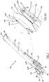
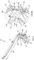
- the apparatus 10 includes at least one conveyor 20, 30 for receiving material processed by the processing unit 12 and outputting the received material from the apparatus 10, e.g. to a stockpile, or to another machine or apparatus (not shown).
- Such conveyors 20, 30 are sometimes referred to as outfeed conveyors.
- the apparatus 10 includes a front conveyor 20 and first and second side conveyors 30 provided on opposite sides of the apparatus 10.
- the conveyors 20, 30 receive material of different grades.
- the conveyors 20, 30 may receive material directly from the processing unit 12, or indirectly via one or more other conveyor (not shown) depending on the embodiment.
- Alternative embodiments may have more or fewer conveyors.
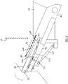
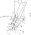
- the second section 42 is coupled to the first section 40 by any convenient moving joint(s) or folding mechanism, for example comprising one or more hinge 46 or pivot joint(s).
- the folding mechanism pivotably couples the second section 42 to the first section 40.
- the preferred configuration is such that the second section 42 is pivotable with respect to the first section 40 about an axis that runs transversely of the conveyor 30, in particular an axis that is perpendicular to the longitudinal or conveying axis of the conveyor 30 when deployed (or unfolded).
- the pivot axis may lie in or parallel with the plane of the main conveying surface 37 when the conveyor is deployed.
- the third foldable section 44 is coupled to the second foldable section 42 by any convenient moving joint(s) or folding mechanism, for example comprising one or more pivot joint 48 or hinge(s).
- the folding mechanism pivotably couples the third section 44 to the second section 42.
- the preferred configuration is such that the third section 44 is pivotable with respect to the second section 42 about an axis that runs perpendicularly to the conveying surface of the conveyor 30.
- extension of the actuator 47 moves the second section 42 from the deployed state to the non-deployed state
- retraction of the actuator 47 moves the second section 42 from the non-deployed state to the deployed state, although the reverse operation may apply depending on where the actuator 46 is located.
- the skirting 60A, 60B may be coupled to the respective skirting support 62A, 62B by any convenient coupling means.
- the coupling means comprises a flexible line 66, e.g. a wire, rope, cable or chain, that is preferably spring-tensioned.
- the line 66 is connected to a spring 68, conveniently a tension spring, for spring-tensioning the line 66.
- the line 66 may be wholly or partly formed from an elastic material.
- the line 66 may be connected to a manual tensioning device, or have no tensioning means.
- the line 66 When the second section 42 of the conveyor 30 is in its deployed state, and the skirting support 62A, 62B is deployed, the line 66 is in a raised position with respect to the second section 42, e. g. raised with respect to the conveying surface, held in tension (typically between the skirting support 62A, 62B and the first section 40) and holds the respective skirting 60A, 60B in its deployed state (see Fig. 3 for example). In preferred embodiments, the line 66 holds the respective skirting 60A, 60B in tension when the skirting is deployed.
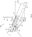
- the line 66 When the second section 42 is in its non-deployed state and the skirting support 62A, 62B is in its non-deployed state, the line 66 is in a lowered position with respect to the second section 42, e.g. closer to the conveying surface, and causes the respective skirting 60A, 60B to adopt its non-deployed state (see Fig. 4 for example).
- the line 66 is not tensioned when the second section 42 is in its non-deployed state and the skirting support 62A, 62B is in its non-deployed state.
- the respective skirting 60A, 60B when the line 66 is not tensioned, the respective skirting 60A, 60B is not tensioned which facilitates its deformation or folding into its non-deployed state.
- the support 62A, 62B is pivotable between its deployed and non-deployed states such that the coupling point 64 moves downwardly, typically towards the conveying surface, as the support 62A, 62B pivots from the deployed state to the non-deployed state, and moves upwardly, typically away from the conveying surface, as the support 62A, 62B pivots from the non-deployed state to the deployed state.
- the linkage 70 comprises at least one rigid structure, for example a bar or rod.
- the rigid linkage 70 is pivotably coupled to the first section 40 and to the skirting support 62A, 62B.
- the linkage 70 is coupled to a portion 63 of the skirting support 62A, 62B at a coupling point 71 such that the pivot axis P is located between the coupling points 64, 71.
- the linkage 70 acts on the skirting support 62A, 62B at coupling point 71 to pivot the skirting support 62A, 62B about pivot axis P in a lever-like manner.
- the preferred arrangement is such that, as the second section 42 moves out of its deployed state towards and into its non-deployed state, the pivot axis P moves closer to the point 72 at which the linkage 70 is coupled to the first section 40. As a result, the action of the linkage 70 on the portion 63 causes the skirting support 62A, 62B to pivot about axis P towards and into its non-deployed state. As the second section 42 moves out of its non-deployed state towards and into its deployed state, the pivot axis P moves further away from the point 72 at which the linkage 70 is coupled to the first section 40. As a result, the action of the linkage 70 on the portion 63 causes the skirting support 62A, 62B to pivot about axis P towards and into its deployed state.
- Figures 6 and 7 illustrate a second embodiment of a foldable conveyor 130 in which like numerals are used to denote like parts and in respect of which the same description applies as is provided in relation to the embodiment of Figures 1 to 5 unless otherwise indicated.
- the linkage 170 comprises a flexible, and preferably inelastic, line, e.g. a wire, rope, cable or chain.
- resilient biasing means 175, for example one or more spring are coupled between the skirting support 62A and the second section 42 (or other convenient base structure with respect to which the skirting support is movable) and arranged to urge the skirting support 62A into its non-deployed state.
- the spring 175 (or other biasing means) is coupled to the coupling point 71.
- the arrangement is such that, with the second section 42 in its deployed state, the tension in the line 170 holds the skirting support 62A in its deployed state against the bias of the spring 175 (or other biasing means), as shown in Figure 6 .
- the coupling point 71 moves closer to the coupling point 72 with the result that the line 170 is detensioned to allow the biasing means 175 to move the skirting support 62A towards and into its non-deployed state ( Figure 7 ).
- Figures 8 and 9 illustrate a third embodiment of a foldable conveyor 230 in which like numerals are used to denote like parts and in respect of which the same description applies as is provided in relation to the embodiment of Figures 1 to 5 unless otherwise indicated.
- the skirting support 262A is movable with respect to the second section 42 from the deployed state to the non-deployed state by engagement with an abutment surface 15A on the body 15 of the apparatus 10 (or on any other structure adjacent the conveyor) as the second section 42 moves into its non-deployed state.
- the skirting support 262A is shaped and dimensioned to engage with any convenient part of the body 15 (or other structure) as the second section 42 pivots with respect to the first section 40 such that further movement of the second section 42 towards the non-deployed state after the engagement causes the skirting support 262A to move into its non-deployed state.
- the skirting support 262A is resiliently biased to adopt its deployed state. Any suitable resilient biasing means 277, e.g. one or more springs, may be provided for this purpose.
- the resilient bias acts to move the skirting support 262A to its deployed state.
- Figures 10 and 11 illustrate a fourth embodiment of a foldable conveyor 330 in which like numerals are used to denote like parts and in respect of which the same description applies as is provided in relation to the embodiment of Figures 1 to 5 unless otherwise indicated.
- the actuating means for moving the skirting support 62A between its deployed and non-deployed states comprises an actuator 380, preferably a linear actuator such as a hydraulic ram or electric linear actuator.
- the actuator 380 is coupled between the skirting support 62A and the second section 42 and is operable to pivot the skirting support 62A about pivot axis P.
- the actuator 380 may be coupled to the skirting support 62A to effect linear movement.
- the first section 40 is a base section of the conveyor 30 corresponding to the feed end 32 and typically including the chute 33.
- the skirting 60A, 60B may be referred to as a chute extension or feedboot extension.
- the first section is not the base section of the conveyor and may for example be a mid-section of the conveyor (i.e. a conveyor section that has a respective other section at each end). More generally, the first and second sections may be any two sections of the conveyor, typically any two adjacent conveyor sections (in the direction of conveying). The first and second conveyor sections are coupled to each other, preferably for pivoting movement about a transverse axis.
Landscapes
- Engineering & Computer Science (AREA)
- Mechanical Engineering (AREA)
- Structure Of Belt Conveyors (AREA)
- Threshing Machine Elements (AREA)
- Pusher Or Impeller Conveyors (AREA)
- Framework For Endless Conveyors (AREA)
- Refuse Collection And Transfer (AREA)
- Auxiliary Devices For And Details Of Packaging Control (AREA)
Applications Claiming Priority (1)
| Application Number | Priority Date | Filing Date | Title |
|---|---|---|---|
| GB2018490.9A GB2601198B (en) | 2020-11-24 | 2020-11-24 | Foldable conveyor with deployable skirting |
Publications (2)
| Publication Number | Publication Date |
|---|---|
| EP4001181A1 true EP4001181A1 (fr) | 2022-05-25 |
| EP4001181B1 EP4001181B1 (fr) | 2023-08-09 |
Family
ID=74046856
Family Applications (1)
| Application Number | Title | Priority Date | Filing Date |
|---|---|---|---|
| EP21209677.0A Active EP4001181B1 (fr) | 2020-11-24 | 2021-11-22 | Convoyeur pliable avec joues déployables |
Country Status (7)
| Country | Link |
|---|---|
| US (1) | US11639273B2 (fr) |
| EP (1) | EP4001181B1 (fr) |
| AU (1) | AU2021269435A1 (fr) |
| CA (1) | CA3139650A1 (fr) |
| FI (1) | FI4001181T3 (fr) |
| GB (1) | GB2601198B (fr) |
| PL (1) | PL4001181T3 (fr) |
Families Citing this family (1)
| Publication number | Priority date | Publication date | Assignee | Title |
|---|---|---|---|---|
| GB2630319B (en) * | 2023-05-23 | 2025-07-09 | Roco9 Ltd | Folding conveyor with automatic folding side skirt |
Citations (6)
| Publication number | Priority date | Publication date | Assignee | Title |
|---|---|---|---|---|
| US4462520A (en) * | 1982-08-04 | 1984-07-31 | Strehlow Robert W | Retractable skirt gate |
| JPS63183113U (fr) * | 1987-05-16 | 1988-11-25 | ||
| AU2254799A (en) * | 1990-11-22 | 1999-05-27 | Dragox Pty Ltd | Conveyor skirtboard sealing system |
| JP2001354316A (ja) * | 2000-06-14 | 2001-12-25 | Tcm Corp | ベルトコンベヤのこぼれ防止装置 |
| US20020139643A1 (en) * | 2000-02-07 | 2002-10-03 | Jeff Peltier | Conveyor system |
| US20150144465A1 (en) * | 2013-11-28 | 2015-05-28 | Beumer Gmbh & Co. Kg | Telescopic conveyor belt |
Family Cites Families (6)
| Publication number | Priority date | Publication date | Assignee | Title |
|---|---|---|---|---|
| US3828916A (en) * | 1973-09-26 | 1974-08-13 | P Patz | Multisection conveyor having adjustable elbow between adjacent conveyor sections |
| US4478548A (en) * | 1981-08-17 | 1984-10-23 | Heimes Daniel A | Forage accumulator box |
| SE452303B (sv) * | 1986-03-12 | 1987-11-23 | Consilium Marine Ab | Utmatningsanordning i godsfickor |
| US6170646B1 (en) * | 1999-03-24 | 2001-01-09 | Todd Kaeb | Cleated belt adaptable to curvilinear shapes |
| US9055714B2 (en) * | 2011-04-29 | 2015-06-16 | Green Industry Innovators, L.L.C. | Self-propelled power unit with removable attachment assembly |
| EP2894116B1 (fr) * | 2014-01-14 | 2019-08-21 | Portafill International Limited | Ensemble d' un transporteur pliable |
-
2020
- 2020-11-24 GB GB2018490.9A patent/GB2601198B/en active Active
-
2021
- 2021-11-19 AU AU2021269435A patent/AU2021269435A1/en active Pending
- 2021-11-19 CA CA3139650A patent/CA3139650A1/fr active Pending
- 2021-11-22 EP EP21209677.0A patent/EP4001181B1/fr active Active
- 2021-11-22 PL PL21209677.0T patent/PL4001181T3/pl unknown
- 2021-11-22 US US17/532,210 patent/US11639273B2/en active Active
- 2021-11-22 FI FIEP21209677.0T patent/FI4001181T3/fi active
Patent Citations (6)
| Publication number | Priority date | Publication date | Assignee | Title |
|---|---|---|---|---|
| US4462520A (en) * | 1982-08-04 | 1984-07-31 | Strehlow Robert W | Retractable skirt gate |
| JPS63183113U (fr) * | 1987-05-16 | 1988-11-25 | ||
| AU2254799A (en) * | 1990-11-22 | 1999-05-27 | Dragox Pty Ltd | Conveyor skirtboard sealing system |
| US20020139643A1 (en) * | 2000-02-07 | 2002-10-03 | Jeff Peltier | Conveyor system |
| JP2001354316A (ja) * | 2000-06-14 | 2001-12-25 | Tcm Corp | ベルトコンベヤのこぼれ防止装置 |
| US20150144465A1 (en) * | 2013-11-28 | 2015-05-28 | Beumer Gmbh & Co. Kg | Telescopic conveyor belt |
Also Published As
| Publication number | Publication date |
|---|---|
| GB202018490D0 (en) | 2021-01-06 |
| PL4001181T3 (pl) | 2024-01-29 |
| GB2601198A (en) | 2022-05-25 |
| GB2601198B (en) | 2024-01-03 |
| FI4001181T3 (fi) | 2023-11-06 |
| US11639273B2 (en) | 2023-05-02 |
| CA3139650A1 (fr) | 2022-05-24 |
| AU2021269435A1 (en) | 2022-06-09 |
| EP4001181B1 (fr) | 2023-08-09 |
| US20220162011A1 (en) | 2022-05-26 |
Similar Documents
| Publication | Publication Date | Title |
|---|---|---|
| US9427745B2 (en) | Material processing apparatus with multi-mode feed conveyor assembly | |
| CA2680081C (fr) | Ossature pliable pour transporteur auxiliaire | |
| US20140202835A1 (en) | Material processing apparatus with deployable feed conveyor | |
| JP6226877B2 (ja) | 原料処理設備 | |
| US9725249B2 (en) | Movable processing apparatus for mineral material processing | |
| EP2768750B1 (fr) | Structure de support de transporteur pliable présentant une aptitude au déploiement de façon recouvrant | |
| EP2664492B1 (fr) | Mécanisme de pliage à fonction de verrouillage | |
| EP4001181B1 (fr) | Convoyeur pliable avec joues déployables | |
| US7264104B2 (en) | Crusher in-feed conveyor method and apparatus | |
| WO2015022112A1 (fr) | Châssis principal pour appareil de traitement en vrac mobile | |
| US20220111396A1 (en) | Material Processing Equipment | |
| IE970078A1 (en) | A mobile screen | |
| JP2012218870A (ja) | コンベヤ | |
| JP2012016649A (ja) | 振動スクリーン | |
| GB2306128A (en) | Mobile Screening Apparatus |
Legal Events
| Date | Code | Title | Description |
|---|---|---|---|
| PUAI | Public reference made under article 153(3) epc to a published international application that has entered the european phase |
Free format text: ORIGINAL CODE: 0009012 |
|
| STAA | Information on the status of an ep patent application or granted ep patent |
Free format text: STATUS: THE APPLICATION HAS BEEN PUBLISHED |
|
| AK | Designated contracting states |
Kind code of ref document: A1 Designated state(s): AL AT BE BG CH CY CZ DE DK EE ES FI FR GB GR HR HU IE IS IT LI LT LU LV MC MK MT NL NO PL PT RO RS SE SI SK SM TR |
|
| STAA | Information on the status of an ep patent application or granted ep patent |
Free format text: STATUS: REQUEST FOR EXAMINATION WAS MADE |
|
| 17P | Request for examination filed |
Effective date: 20220830 |
|
| RBV | Designated contracting states (corrected) |
Designated state(s): AL AT BE BG CH CY CZ DE DK EE ES FI FR GB GR HR HU IE IS IT LI LT LU LV MC MK MT NL NO PL PT RO RS SE SI SK SM TR |
|
| RIC1 | Information provided on ipc code assigned before grant |
Ipc: B65G 41/00 19680901ALI20230111BHEP Ipc: B65G 21/20 19680901ALI20230111BHEP Ipc: B65G 21/10 19680901AFI20230111BHEP |
|
| GRAP | Despatch of communication of intention to grant a patent |
Free format text: ORIGINAL CODE: EPIDOSNIGR1 |
|
| STAA | Information on the status of an ep patent application or granted ep patent |
Free format text: STATUS: GRANT OF PATENT IS INTENDED |
|
| INTG | Intention to grant announced |
Effective date: 20230228 |
|
| GRAS | Grant fee paid |
Free format text: ORIGINAL CODE: EPIDOSNIGR3 |
|
| GRAA | (expected) grant |
Free format text: ORIGINAL CODE: 0009210 |
|
| STAA | Information on the status of an ep patent application or granted ep patent |
Free format text: STATUS: THE PATENT HAS BEEN GRANTED |
|
| P01 | Opt-out of the competence of the unified patent court (upc) registered |
Effective date: 20230531 |
|
| AK | Designated contracting states |
Kind code of ref document: B1 Designated state(s): AL AT BE BG CH CY CZ DE DK EE ES FI FR GB GR HR HU IE IS IT LI LT LU LV MC MK MT NL NO PL PT RO RS SE SI SK SM TR |
|
| REG | Reference to a national code |
Ref country code: GB Ref legal event code: FG4D |
|
| REG | Reference to a national code |
Ref country code: CH Ref legal event code: EP |
|
| REG | Reference to a national code |
Ref country code: DE Ref legal event code: R096 Ref document number: 602021004151 Country of ref document: DE |
|
| REG | Reference to a national code |
Ref country code: IE Ref legal event code: FG4D |
|
| REG | Reference to a national code |
Ref country code: FI Ref legal event code: FGE |
|
| REG | Reference to a national code |
Ref country code: LT Ref legal event code: MG9D |
|
| REG | Reference to a national code |
Ref country code: NL Ref legal event code: MP Effective date: 20230809 |
|
| PG25 | Lapsed in a contracting state [announced via postgrant information from national office to epo] |
Ref country code: GR Free format text: LAPSE BECAUSE OF FAILURE TO SUBMIT A TRANSLATION OF THE DESCRIPTION OR TO PAY THE FEE WITHIN THE PRESCRIBED TIME-LIMIT Effective date: 20231110 |
|
| PG25 | Lapsed in a contracting state [announced via postgrant information from national office to epo] |
Ref country code: IS Free format text: LAPSE BECAUSE OF FAILURE TO SUBMIT A TRANSLATION OF THE DESCRIPTION OR TO PAY THE FEE WITHIN THE PRESCRIBED TIME-LIMIT Effective date: 20231209 |
|
| PG25 | Lapsed in a contracting state [announced via postgrant information from national office to epo] |
Ref country code: SE Free format text: LAPSE BECAUSE OF FAILURE TO SUBMIT A TRANSLATION OF THE DESCRIPTION OR TO PAY THE FEE WITHIN THE PRESCRIBED TIME-LIMIT Effective date: 20230809 Ref country code: RS Free format text: LAPSE BECAUSE OF FAILURE TO SUBMIT A TRANSLATION OF THE DESCRIPTION OR TO PAY THE FEE WITHIN THE PRESCRIBED TIME-LIMIT Effective date: 20230809 Ref country code: PT Free format text: LAPSE BECAUSE OF FAILURE TO SUBMIT A TRANSLATION OF THE DESCRIPTION OR TO PAY THE FEE WITHIN THE PRESCRIBED TIME-LIMIT Effective date: 20231211 Ref country code: NO Free format text: LAPSE BECAUSE OF FAILURE TO SUBMIT A TRANSLATION OF THE DESCRIPTION OR TO PAY THE FEE WITHIN THE PRESCRIBED TIME-LIMIT Effective date: 20231109 Ref country code: NL Free format text: LAPSE BECAUSE OF FAILURE TO SUBMIT A TRANSLATION OF THE DESCRIPTION OR TO PAY THE FEE WITHIN THE PRESCRIBED TIME-LIMIT Effective date: 20230809 Ref country code: LV Free format text: LAPSE BECAUSE OF FAILURE TO SUBMIT A TRANSLATION OF THE DESCRIPTION OR TO PAY THE FEE WITHIN THE PRESCRIBED TIME-LIMIT Effective date: 20230809 Ref country code: LT Free format text: LAPSE BECAUSE OF FAILURE TO SUBMIT A TRANSLATION OF THE DESCRIPTION OR TO PAY THE FEE WITHIN THE PRESCRIBED TIME-LIMIT Effective date: 20230809 Ref country code: IS Free format text: LAPSE BECAUSE OF FAILURE TO SUBMIT A TRANSLATION OF THE DESCRIPTION OR TO PAY THE FEE WITHIN THE PRESCRIBED TIME-LIMIT Effective date: 20231209 Ref country code: HR Free format text: LAPSE BECAUSE OF FAILURE TO SUBMIT A TRANSLATION OF THE DESCRIPTION OR TO PAY THE FEE WITHIN THE PRESCRIBED TIME-LIMIT Effective date: 20230809 Ref country code: GR Free format text: LAPSE BECAUSE OF FAILURE TO SUBMIT A TRANSLATION OF THE DESCRIPTION OR TO PAY THE FEE WITHIN THE PRESCRIBED TIME-LIMIT Effective date: 20231110 |
|
| PG25 | Lapsed in a contracting state [announced via postgrant information from national office to epo] |
Ref country code: ES Free format text: LAPSE BECAUSE OF FAILURE TO SUBMIT A TRANSLATION OF THE DESCRIPTION OR TO PAY THE FEE WITHIN THE PRESCRIBED TIME-LIMIT Effective date: 20230809 |
|
| PG25 | Lapsed in a contracting state [announced via postgrant information from national office to epo] |
Ref country code: SM Free format text: LAPSE BECAUSE OF FAILURE TO SUBMIT A TRANSLATION OF THE DESCRIPTION OR TO PAY THE FEE WITHIN THE PRESCRIBED TIME-LIMIT Effective date: 20230809 Ref country code: RO Free format text: LAPSE BECAUSE OF FAILURE TO SUBMIT A TRANSLATION OF THE DESCRIPTION OR TO PAY THE FEE WITHIN THE PRESCRIBED TIME-LIMIT Effective date: 20230809 Ref country code: ES Free format text: LAPSE BECAUSE OF FAILURE TO SUBMIT A TRANSLATION OF THE DESCRIPTION OR TO PAY THE FEE WITHIN THE PRESCRIBED TIME-LIMIT Effective date: 20230809 Ref country code: EE Free format text: LAPSE BECAUSE OF FAILURE TO SUBMIT A TRANSLATION OF THE DESCRIPTION OR TO PAY THE FEE WITHIN THE PRESCRIBED TIME-LIMIT Effective date: 20230809 Ref country code: DK Free format text: LAPSE BECAUSE OF FAILURE TO SUBMIT A TRANSLATION OF THE DESCRIPTION OR TO PAY THE FEE WITHIN THE PRESCRIBED TIME-LIMIT Effective date: 20230809 Ref country code: CZ Free format text: LAPSE BECAUSE OF FAILURE TO SUBMIT A TRANSLATION OF THE DESCRIPTION OR TO PAY THE FEE WITHIN THE PRESCRIBED TIME-LIMIT Effective date: 20230809 Ref country code: SK Free format text: LAPSE BECAUSE OF FAILURE TO SUBMIT A TRANSLATION OF THE DESCRIPTION OR TO PAY THE FEE WITHIN THE PRESCRIBED TIME-LIMIT Effective date: 20230809 |
|
| REG | Reference to a national code |
Ref country code: DE Ref legal event code: R097 Ref document number: 602021004151 Country of ref document: DE |
|
| PG25 | Lapsed in a contracting state [announced via postgrant information from national office to epo] |
Ref country code: IT Free format text: LAPSE BECAUSE OF FAILURE TO SUBMIT A TRANSLATION OF THE DESCRIPTION OR TO PAY THE FEE WITHIN THE PRESCRIBED TIME-LIMIT Effective date: 20230809 |
|
| PLBE | No opposition filed within time limit |
Free format text: ORIGINAL CODE: 0009261 |
|
| STAA | Information on the status of an ep patent application or granted ep patent |
Free format text: STATUS: NO OPPOSITION FILED WITHIN TIME LIMIT |
|
| REG | Reference to a national code |
Ref country code: AT Ref legal event code: UEP Ref document number: 1597321 Country of ref document: AT Kind code of ref document: T Effective date: 20230809 |
|
| PG25 | Lapsed in a contracting state [announced via postgrant information from national office to epo] |
Ref country code: MC Free format text: LAPSE BECAUSE OF FAILURE TO SUBMIT A TRANSLATION OF THE DESCRIPTION OR TO PAY THE FEE WITHIN THE PRESCRIBED TIME-LIMIT Effective date: 20230809 |
|
| PG25 | Lapsed in a contracting state [announced via postgrant information from national office to epo] |
Ref country code: LU Free format text: LAPSE BECAUSE OF NON-PAYMENT OF DUE FEES Effective date: 20231122 |
|
| 26N | No opposition filed |
Effective date: 20240513 |
|
| PG25 | Lapsed in a contracting state [announced via postgrant information from national office to epo] |
Ref country code: MC Free format text: LAPSE BECAUSE OF FAILURE TO SUBMIT A TRANSLATION OF THE DESCRIPTION OR TO PAY THE FEE WITHIN THE PRESCRIBED TIME-LIMIT Effective date: 20230809 Ref country code: LU Free format text: LAPSE BECAUSE OF NON-PAYMENT OF DUE FEES Effective date: 20231122 Ref country code: SI Free format text: LAPSE BECAUSE OF FAILURE TO SUBMIT A TRANSLATION OF THE DESCRIPTION OR TO PAY THE FEE WITHIN THE PRESCRIBED TIME-LIMIT Effective date: 20230809 |
|
| PG25 | Lapsed in a contracting state [announced via postgrant information from national office to epo] |
Ref country code: BG Free format text: LAPSE BECAUSE OF FAILURE TO SUBMIT A TRANSLATION OF THE DESCRIPTION OR TO PAY THE FEE WITHIN THE PRESCRIBED TIME-LIMIT Effective date: 20230809 |
|
| PG25 | Lapsed in a contracting state [announced via postgrant information from national office to epo] |
Ref country code: BG Free format text: LAPSE BECAUSE OF FAILURE TO SUBMIT A TRANSLATION OF THE DESCRIPTION OR TO PAY THE FEE WITHIN THE PRESCRIBED TIME-LIMIT Effective date: 20230809 |
|
| REG | Reference to a national code |
Ref country code: CH Ref legal event code: PL |
|
| REG | Reference to a national code |
Ref country code: CH Ref legal event code: PL |
|
| PG25 | Lapsed in a contracting state [announced via postgrant information from national office to epo] |
Ref country code: CH Free format text: LAPSE BECAUSE OF NON-PAYMENT OF DUE FEES Effective date: 20241130 |
|
| PG25 | Lapsed in a contracting state [announced via postgrant information from national office to epo] |
Ref country code: CY Free format text: LAPSE BECAUSE OF FAILURE TO SUBMIT A TRANSLATION OF THE DESCRIPTION OR TO PAY THE FEE WITHIN THE PRESCRIBED TIME-LIMIT; INVALID AB INITIO Effective date: 20211122 |
|
| PG25 | Lapsed in a contracting state [announced via postgrant information from national office to epo] |
Ref country code: TR Free format text: LAPSE BECAUSE OF FAILURE TO SUBMIT A TRANSLATION OF THE DESCRIPTION OR TO PAY THE FEE WITHIN THE PRESCRIBED TIME-LIMIT Effective date: 20230809 |
|
| PGFP | Annual fee paid to national office [announced via postgrant information from national office to epo] |
Ref country code: DE Payment date: 20251119 Year of fee payment: 5 |
|
| PGFP | Annual fee paid to national office [announced via postgrant information from national office to epo] |
Ref country code: GB Payment date: 20251121 Year of fee payment: 5 |
|
| PGFP | Annual fee paid to national office [announced via postgrant information from national office to epo] |
Ref country code: AT Payment date: 20260113 Year of fee payment: 5 |
|
| PGFP | Annual fee paid to national office [announced via postgrant information from national office to epo] |
Ref country code: FI Payment date: 20251125 Year of fee payment: 5 |
|
| PGFP | Annual fee paid to national office [announced via postgrant information from national office to epo] |
Ref country code: FR Payment date: 20251126 Year of fee payment: 5 |
|
| PGFP | Annual fee paid to national office [announced via postgrant information from national office to epo] |
Ref country code: BE Payment date: 20251119 Year of fee payment: 5 |
|
| PGFP | Annual fee paid to national office [announced via postgrant information from national office to epo] |
Ref country code: IE Payment date: 20251121 Year of fee payment: 5 |
|
| PGFP | Annual fee paid to national office [announced via postgrant information from national office to epo] |
Ref country code: PL Payment date: 20251024 Year of fee payment: 5 |
|
| PG25 | Lapsed in a contracting state [announced via postgrant information from national office to epo] |
Ref country code: HU Free format text: LAPSE BECAUSE OF FAILURE TO SUBMIT A TRANSLATION OF THE DESCRIPTION OR TO PAY THE FEE WITHIN THE PRESCRIBED TIME-LIMIT; INVALID AB INITIO Effective date: 20211122 |