EP4001205A1 - Dispositif de levage d'une remorque de train de manutention et remorque de train de manutention comportant un dispositif de levage - Google Patents
Dispositif de levage d'une remorque de train de manutention et remorque de train de manutention comportant un dispositif de levage Download PDFInfo
- Publication number
- EP4001205A1 EP4001205A1 EP21201154.8A EP21201154A EP4001205A1 EP 4001205 A1 EP4001205 A1 EP 4001205A1 EP 21201154 A EP21201154 A EP 21201154A EP 4001205 A1 EP4001205 A1 EP 4001205A1
- Authority
- EP
- European Patent Office
- Prior art keywords
- lifting device
- support rail
- lifting
- tugger train
- vertical
- Prior art date
- Legal status (The legal status is an assumption and is not a legal conclusion. Google has not performed a legal analysis and makes no representation as to the accuracy of the status listed.)
- Granted
Links
Images


Classifications
-
- B—PERFORMING OPERATIONS; TRANSPORTING
- B62—LAND VEHICLES FOR TRAVELLING OTHERWISE THAN ON RAILS
- B62D—MOTOR VEHICLES; TRAILERS
- B62D53/00—Tractor-trailer combinations; Road trains
- B62D53/005—Combinations with at least three axles and comprising two or more articulated parts
-
- B—PERFORMING OPERATIONS; TRANSPORTING
- B66—HOISTING; LIFTING; HAULING
- B66F—HOISTING, LIFTING, HAULING OR PUSHING, NOT OTHERWISE PROVIDED FOR, e.g. DEVICES WHICH APPLY A LIFTING OR PUSHING FORCE DIRECTLY TO THE SURFACE OF A LOAD
- B66F9/00—Devices for lifting or lowering bulky or heavy goods for loading or unloading purposes
- B66F9/06—Devices for lifting or lowering bulky or heavy goods for loading or unloading purposes movable, with their loads, on wheels or the like, e.g. fork-lift trucks
Definitions
- the invention relates to a lifting device of a tugger train trailer for lifting and lowering a load carrier carried in the tugger train trailer, wherein the lifting device for raising and lowering the load carrier has at least one support rail that is height-adjustable in the vertical direction and is designed to reach under the load carrier.
- the invention also relates to a tugger train trailer with a chassis and a lifting device.
- the invention further relates to a system comprising such a tugger train trailer and at least one load carrier.
- tugger trains are increasingly being used, which consist of a towing vehicle, for example a tractor, and a plurality of tugger train trailers attached to the tractor, on which the charges are transported.
- a tugger train trailer with a chassis which includes a front axle module and a rear axle module.
- the front axle module and the rear axle module each comprise a lifting mast profile, in which a transport device receiving the load is arranged such that it can be raised and lowered.
- the raisable and lowerable transport device has according to the figure 4 the DE 10 2014 100 865 A1 Support rails, which are also referred to as lifting lips, with which a designed as a trolley floor roller can be raised and lowered as a load carrier.
- the support rails are formed by rigid support rails that perform a purely vertical lifting movement.
- a corresponding floor roller which has a support plate as a rectangular support frame, with a roller being arranged directly on the underside of the support plate at the four corner areas, with which the floor roller is supported on a roadway.
- the floor roller can be pushed or pulled over short distances, for example by one person by hand.
- the floor roller can be lifted and transported in tugger train trailers with the support rails that can be raised and lowered.
- the tugger train trailer for each floor roller is provided with two support rails that can be raised and lowered, which reach under and lift the support frame of the floor roller on opposite sides.
- the object of the present invention is to provide a lifting device for a tugger train trailer and a tugger train trailer with a lifting device that avoids the disadvantages mentioned above.
- a lifting device of a tugger train trailer for lifting and lowering a load carrier carried in the tugger train trailer wherein the lifting device for raising and lowering the load carrier has at least one support rail that is height-adjustable in the vertical direction and is designed to reach under the load carrier, the Support rail is movable in the horizontal direction between a retracted position and an extended position.
- support rails according to the invention which are movable in the horizontal direction between a retracted position and an extended position, the problem of interference contour between support rail and rollers of the floor roller, the are arranged flush with the outer contour of the support frame of the floor roller can be solved in a simple manner.
- the support rails When pushing the floor roller into the tugger train trailer, the support rails are in the retracted position.
- the support rails are only actuated in the extended position in which the support rails can reach under the floor roller on the support frame when the floor roller has been pushed into the tugger train trailer and is in the right place.
- floor rollers with rollers arranged flush on the outer contour can thus also be transported with the tugger train trailer, so that the tugger train trailer can be used universally for different load carriers.
- a drive that is independent of the lifting device can be provided for moving the support rail in the horizontal direction.
- the lifting device is designed in such a way that a horizontal movement of the support rail from the retracted position to the extended position in the horizontal direction and a vertical movement of the support rail, subsequent to the horizontal movement, from a lowered position to a raised position in the vertical direction to create.
- the lifting device has a lifting actuator which is operatively connected to at least one support rail by means of a coupling device, the coupling device being designed to transform a vertical lifting movement of the lifting actuator into a horizontal movement from the retracted position to the extended position and in to convert the vertical movement subsequent to the horizontal movement from the lowered position to the raised position of the support rail.
- the support rail is thus mechanically coupled to the lifting actuator by means of the coupling device in such a way that the vertical lifting movement of the lifting actuator is converted into the horizontal movement and the subsequent vertical movement of the support rail.
- the coupling device is designed such that in a first lifting range of the lifting actuator, the horizontal movement of the support rail from the retracted position to the extended position and in a subsequent second lifting range, the vertical movement of the support rail from the lowered Position can be generated in the raised position.
- the support rail is thus guided mechanically by means of the coupling device in such a way that the lifting actuator generates the horizontal movement of the support rail in a first lifting range of the lifting actuator and the vertical movement of the support rail in a subsequent second lifting range, so that the lifting actuator first moves the support rails of to pick up a load carrier from the retracted position to the extended position and then raises the support rails from the lowered position to the raised position or, to set down a load carrier, first lowers the support rails from the raised position to the lowered position and then the support rails from the extended position to the retracted position enter position.
- the coupling device has a link element which is provided with at least one L-shaped link, in particular an L-shaped slot, in which the support rail is guided.
- L-shaped connecting link which preferably has a horizontal leg and a vertical leg, in which the support rail is guided, a horizontal movement of the support rail from the retracted position to the extended position and a movement subsequent to the horizontal movement can be carried out in a simple manner vertical movement of the support rail from the lowered position to the raised position.
- the support rail is guided in the L-shaped connecting link according to one embodiment of the invention by means of a guide element, in particular a roller or a sliding block.
- a guide element in particular a roller or a sliding block.
- the coupling device has an actuating element which is in operative connection with the lifting actuator and which has at least one driver recess, in particular a slot, in which the support rail is guided with the guide element.
- the lifting actuator thus actuates the support rail by means of the actuating element.
- the support rail is guided in this case by means of the guide element in the L-shaped link of the link element and in the driver recess of the actuating element, whereby the vertical movement of the lifting actuator and thus the vertical movement of the actuating element is easily converted into the horizontal movement defined by the L-shaped link from the stowed position to the extended position and subsequent vertical movement from the lowered position to the raised position of the support rail.
- the driver recess is designed as a slot inclined relative to the vertical. With the extent of the inclined slot in the vertical direction, the size of the first lifting range of the lifting actuator can be specified in a simple manner, in which the horizontal movement of the support rail from the retracted position to the extended position is generated.
- the actuating element is guided in the vertical direction on the link element.
- the object is also achieved by a tugger train trailer with a chassis that has two axle modules spaced apart in the vehicle longitudinal direction, between which at least one carried load carrier can be accommodated, the tugger train trailer being provided with a lifting device according to the invention.
- the tugger train trailer has a bridge frame connecting the axle modules, which has vertical supports arranged on the axle modules and a longitudinal beam connecting the vertical supports, with a lifting device according to the invention having a support rail being arranged on each of the vertical supports.
- the bridge frame connects and spans the two axle modules between which one or more load carriers are arranged.
- Lifting devices which each have a support rail, can accommodate one or more load carriers in a simple manner.
- a vertical central beam is arranged on the longitudinal beam, with a lifting device having two support rails being arranged on the central beam, two load carriers can be picked up and transported in a simple manner with the rod pull trailer.
- the support rails each run in the vehicle transverse direction of the tugger train trailer and the horizontal movement of the support rails runs in the vehicle longitudinal direction of the tugger train trailer.
- the load carrier can thus be inserted in the transverse direction of the vehicle between the support rails that are in the retracted position without causing disruptive contours for the support rails.
- the invention further relates to a system comprising a tugger train trailer according to the invention and at least one load carrier, wherein the receiving rails can be brought into operative connection with the underside of a component of the load carrier.
- the mounting rails thus reach under a corresponding component of the load carrier in order to lift it in the tugger train trailer.
- the load carrier can be designed as a floor roller, which has a supporting frame provided with rollers.
- the load carrier can also be in the form of a pallet, for example a Euro pallet, or a lattice box or driverless transport vehicle.
- the invention has a number of advantages.
- a tugger train trailer equipped with the support rails according to the invention can lift and transport a wide variety of load carriers, for example pallets, lattice boxes, floor rollers or driverless transport vehicles, provided that the corresponding load carriers can be reached under by the support rails.
- load carriers for example pallets, lattice boxes, floor rollers or driverless transport vehicles, provided that the corresponding load carriers can be reached under by the support rails.
- the tugger train trailer 1 has a chassis 2, which has two axle modules 2a, 2b arranged spaced apart in the longitudinal direction L of the vehicle.
- the axle module 2a is designed as a front axle module and is provided with front wheels 3 .
- the axle module 2b is designed as a rear axle module and is provided with rear wheels 4 .
- a steerable drawbar 5 is arranged on the axle module 2a, with which the tugger train trailer 1 can be attached to a towing vehicle or a tugger train trailer traveling ahead of the tugger train.
- the axle module 2b is provided with a hitch 6 to which another tugger train trailer of the tugger train can be attached.
- the front wheels 3 and/or the rear wheels 4 can be steered. If both the front wheels 3 and the rear wheels 4 are steered, the steering movement of the front wheels and the steering movement of the rear wheels can be coupled.
- At least one load carrier can be transported between the axle module 2a and the axle module 2b.
- the tugger train trailer 1 has a plurality of support rails 11-14 for receiving the at least one load carrier.
- the tugger train trailer 1 is designed to accommodate two load carriers.
- the tugger train trailer 1 has to accommodate a front load carrier two in the vertical direction V height-adjustable support rails 11, 12 and for receiving a rear load carrier two height-adjustable support rails 13, 14.
- the support rails 11-14 each run in the transverse direction Q of the vehicle.
- the tugger train trailer 1 has a bridge frame 15 connecting the axle modules 2a, 2b, which has vertical supports 16a, 16b arranged on the axle modules 2a, 2b and a longitudinal beam 17 connecting the vertical supports 16a, 16b.
- the support rail 11 is arranged to be adjustable in height in the vertical direction V on the front vertical support 16a or on the front axle module 2a by means of a lifting device 20 .
- the support rail 14 is arranged to be adjustable in height in the vertical direction V on the rear vertical support 16b or on the rear axle module 2b by means of a lifting device 20 .
- On the longitudinal beam 17, a vertical center beam 18 is arranged between the two vertical beams 16a, 16b, on which the two support rails 12, 13 are arranged in a height-adjustable manner in the vertical direction V by means of a lifting device 20.
- the front load carrier is pushed into the tugger train trailer 1 in the vehicle transverse direction Q of the tugger train trailer 1 between the support rails 11, 12.
- the receiving rails 11, 12 are designed so that they can reach under the load carrier, so that the load carrier can be raised by means of the lifting device 20 and the receiving rails 11, 12 for transport in the tugger train trailer 1.
- the rear load carrier is pushed into the tugger train trailer 1 in the vehicle transverse direction Q of the tugger train trailer 1 between the support rails 13, 14 for acceptance.
- the receiving rails 13, 14 are designed so that they can reach under the load carrier, so that the load carrier can be raised by means of the lifting device 20 and the receiving rails 13, 14 for transport in the tugger train trailer 1.
- the support rails 11-14 which can be raised and lowered in the vertical direction V, can also be raised and lowered in the horizontal direction, as shown in FIG Embodiment in the vehicle longitudinal direction L of the tugger train trailer 1, movable between a retracted position and an extended position.
- the support rails 11-14 in the retracted position.
- the support rail 11 is retracted forward in the longitudinal direction L of the vehicle.
- the support rail 12 is retracted to the rear in the longitudinal direction L of the vehicle.
- the support rail 13 is retracted forwards in the longitudinal direction L of the vehicle and the support rail 14 is retracted backwards in the longitudinal direction L of the vehicle.
- a distance A is formed between the two front support rails 11, 12 and the two rear support rails 13, 14 in the longitudinal direction L of the vehicle.
- the support rails 11-14 in the extended position.
- the support rail 11 is extended to the rear in the longitudinal direction L of the vehicle.
- the support rail 12 is extended forward in the longitudinal direction L of the vehicle.
- the support rail 13 is extended backwards in the longitudinal direction L of the vehicle and the support rail 14 is extended forwards in the longitudinal direction L of the vehicle.
- a distance B is formed in the vehicle longitudinal direction L, which is smaller than the distance A in the figure 2 is.
- the lifting device 20 is designed such that the lifting device 20 starting from the figure 2 a horizontal movement HB of the corresponding support rails 11-14 from the retracted position to the extended position in the horizontal vehicle longitudinal direction L and a vertical movement VB of the corresponding support rails 11-14 following the horizontal movement HB from the lowered position to the raised position in the vertical direction direction V generated.
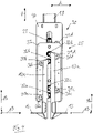
- the structure of the lifting device 20 according to the invention is described below with reference to FIG Figures 4 to 8 described, in which the lifting device 20 is shown on the central support 18, which actuates the two receiving rails 12, 13.
- the lifting device 20 has a lifting actuator 21, for example an electric linear drive, which is connected to the two by means of a coupling device 25 Support rails 12, 13 is in operative connection.
- the lifting actuator 21 is arranged on the central support 18 in such a way that the lifting actuator executes a lifting movement in the vertical V direction.
- the coupling device 25 is designed in such a way that the vertical lifting movement of the lifting actuator 21 is converted into the horizontal movement HB and into the vertical movement VB of the corresponding support rail 12, 13 that follows the horizontal movement HB.
- the coupling device 25 has a link element 30, whose structure in the figure 7 can be seen more closely.
- the link element 30 is provided with at least one L-shaped link 31a, 31b or 31c, 31d, in which the support rail 12 or 13 is guided.
- the L-shaped links 31a, 31b or 31c, 31d are each designed as an L-shaped slot in the exemplary embodiment shown, which have a horizontal section and a vertical section adjoining the horizontal section at its front and rear ends.
- the horizontal sections of the links 31a-31d run in the vehicle longitudinal direction L and the vertical sections of the links 31-31d in the vertical direction.
- the L-shaped link 31b is arranged on the link element 30 at a distance from the L-shaped link 31a in the vertical direction V.
- the L-shaped link 31d is arranged on the link element 30 at a distance from the L-shaped link 31c in the vertical direction V.
- the support rail 12 is guided in the two L-shaped links 31a, 31b.
- the vertical sections of the slot connect to the L-shaped link 31a, 31b at the front end of the horizontal section of the slot.
- the support rail 12 is - as from the figure 4 can be seen - attached to a holder 12a, which is guided by means of a respective guide element 32a, 32b in the L-shaped connecting link 31a, 31b.
- the guide elements 32a, 32b are designed as rollers arranged rotatably on the holder 12a. The diameter of the rollers essentially corresponds to the width BR of the slides 31a, 31b designed as elongated holes.
- the support rail 13 is guided in the two L-shaped links 31c, 31d.
- the vertical sections of the slot connect to the L-shaped link 31c, 31d at the rear end of the horizontal section of the slot.
- the support rail 13 is - as from the figure 4 can be seen - attached to a holder 13a, which is guided by means of a respective guide element 32c, 32d in the L-shaped connecting link 31c, 31d.
- the guide elements 32c, 32d are designed as rollers arranged rotatably on the holder 13a. The diameter of the rollers essentially corresponds to the width BR of the slides 31c, 31d designed as elongated holes.
- the coupling device 20 also has an operating element 35 which is operatively connected to the lifting actuator 21 and whose structure is shown in FIG figure 8 can be seen more closely.
- the actuating element 35 is provided with several driver recesses 36a, 36b, 36c, 36d, in which the support rail 12 or 13 is guided with the guide elements 32a, 32b, 32c, 32d.
- the driver recesses 36a, 36b, 36c, 36d are each formed as a slot in the illustrated embodiment.
- the driver recesses 36a-36d run in the longitudinal direction L of the vehicle and are arranged inclined relative to the vertical V.
- the support rail 12 is guided in the driver recess 36a by means of the guide element 32a designed as a roller and in the driver recess 36b by means of the guide element 32b designed as a roller.
- the support rail 13 is guided in the driver recess 36c by means of the guide element 32c designed as a roller and in the driver recess 36d by means of the guide element 32d designed as a roller.
- the width BR of the entrainment recesses 36a-36d designed as oblong holes essentially corresponds to the diameter of the rollers.
- the actuating element 35 is connected to the lifting actuator 21 in a manner that is not shown in detail, so that the actuating element 35 is actuated in the vertical direction V when the lifting actuator 21 is actuated.
- the actuating element 35 is guided on the link element 30 in the vertical direction.
- the actuating element 35 is for this purpose in the illustrated embodiment two pins 40a, 40b arranged spaced apart in the vertical direction, which are guided in vertical elongated holes 41a, 41b of the connecting link element 30 by means of guide elements, for example rollers, which are not shown in detail.
- the function of the lifting device 20 according to the invention is based on the Figures 4 to 6 explained.
- the figure 4 shows the lower end position of the lifting device 20.
- the lifting actuator 21 is retracted and the actuating element 35 coupled to the lifting actuator 21 is in a lower end position.
- the guide elements 32a, 32b of the support rail 12 are located at the upper ends of the driver recesses 36a, 36b of the actuating element 35 and at the rear ends of the horizontal sections of the L-shaped links 31a, 31b of the link element 30.
- the support rail 12 is thus in one rearward retracted and lowered position.
- the guide elements 32c, 32d of the support rail 13 are located at the upper ends of the driver recesses 36c, 36d of the actuating element 35 and at the front ends of the horizontal sections of the L-shaped links 31c, 31d of the link element 30.
- the support rail 13 is thus in one forward retracted and lowered position.
- the figure 5 shows the lifting device 20 at the end of a first lifting range H1.
- the lifting actuator 21 is extended vertically upwards by the stroke H1 and has raised the actuating element 35 coupled to the lifting actuator 21 by the stroke H1.
- the guide elements 32a, 32b of the support rail 12 are located at the lower ends of the driver recesses 36a, 36b of the actuating element 35 and at the front ends of the horizontal sections of the L-shaped links 31a, 31b of the link element 30.
- the support rail 12 is thus in one forward extended and further lowered position.
- the guide elements 32a, 32b are only guided in the horizontal sections of the L-shaped links 31a, 31b, so that the vertical position of the support rail 12 does not change and in the first lifting range H1 only a horizontal movement HB of the support rail 12 is generated forward in the vehicle longitudinal direction L from the retracted position to the extended position.
- the guide elements 32c, 32d of the support rail 13 are located at the lower ends of the driver recesses 36c, 36d of the actuating element 35 and at the rear Ends of the horizontal sections of the L-shaped links 31c, 31d of the link element 30. The support rail 13 is thus in a rearwardly extended and lowered position.
- the guide elements 32c, 32d are only guided in the horizontal sections of the L-shaped links 31c, 31d, so that the vertical position of the support rail 13 does not change and in the first lifting range H1 only a horizontal movement HB of the support rail 13 is generated rearward in the vehicle longitudinal direction L from the retracted position to the extended position.
- the figure 6 shows the lifting device 20 at the end of a second lifting range H2, which follows the first lifting range H1.
- the lifting actuator 21 is extended vertically upwards by the further stroke H2 and has raised the actuating element 35 coupled to the lifting actuator 21 by the further stroke H2.
- the guide elements 32a, 32b of the support rail 12 remain at the lower ends of the driver recesses 36a, 36b of the actuating element 35 and are guided in the vertical sections of the L-shaped links 31a, 31b of the link element 30 up to their upper ends.
- the support rail 12 is thus in a forwardly extended and raised position.
- the guide elements 32a, 32b are guided only in the vertical sections of the L-shaped links 31a, 31b, so that the horizontal position of the extended support rail 12 does not change in the longitudinal direction L of the vehicle and in the second lifting range H2 only a vertical movement VB of the extended support rail 12 from the lowered position to the raised position in the vertical direction V is generated.
- the guide elements 32c, 32d of the support rail 13 also remain at the lower ends of the driver recesses 36c, 36d of the actuating element 35 and are guided in the vertical sections of the L-shaped links 31c, 31d of the link element 30 up to their upper ends.
- the support rail 13 is thus in a rearwardly extended and raised position.
- the guide elements 32c, 32d are guided only in the vertical sections of the L-shaped links 31c, 31d, so that the horizontal position of the extended support rail 13 does not change in the longitudinal direction L of the vehicle and in the second lifting range H2 only a vertical movement VB of the extended support rail 13 from the lowered position to the raised position in the vertical direction V is generated.
- the coupling device 25 consisting of link element 30 and actuating element 35 is thus designed in such a way that in the first lifting range H1 of the lifting actuator 21 only the corresponding horizontal movement HB of the support rail 12, 13 from the retracted position to the extended position and in the subsequent second Lifting range H2 only the vertical movement VB of the support rail 12, 13 is generated from the lowered position to the raised position.
- the stroke actuator 21 preferably has a total stroke (H1+H2) in the range of 100 mm, with the first stroke range H1 extending over the first 20 mm of the total stroke and the second stroke range H2 extending over the remaining 80 mm of the total stroke.
- the coupling device 25 is preferably designed in such a way that in the first lifting range H1 there is a horizontal movement HB of the support rails 11-14 in the range of 60 mm. Starting from the figure 4 the support rails 11-14 are thus first extended forwards or backwards by 60mm in the horizontal longitudinal direction L of the vehicle during the lifting movement of the lifting actuator 21 ( figure 5 ) and then raised by 80mm in the vertical direction V ( figure 6 ).
- the lifting actuator 21 makes the total stroke of 100 mm, with the first lifting range H1 of the lifting actuator 21 of 20 mm being converted into the horizontal movement HB of the support rails 11-14 and the second lifting range H2 of the lifting actuator 21 of 80 mm being converted into the vertical movement VB of the support rails 11 -14 is converted.
- the structure of the lifting device 20 of the support rail 11 corresponds to the structure of the lifting device 20 of the support rail 13 and the structure of the lifting device 20 of the support rail 14 corresponds to the structure of the lifting device 20 of the support rail 12 .
- the support rails are 11-14 in the position according to the figure 4 with lowered and retracted support rails 11-14.
- a load carrier for example a floor roller
- the support rails can 11-14 in the position of figure 5 be extended and then in the position of figure 6 be raised, so that the load carrier is reached under and lifted by the support rails 11, 12 or 13, 14.
Landscapes
- Engineering & Computer Science (AREA)
- Transportation (AREA)
- Structural Engineering (AREA)
- Mechanical Engineering (AREA)
- Civil Engineering (AREA)
- Life Sciences & Earth Sciences (AREA)
- Geology (AREA)
- Chemical & Material Sciences (AREA)
- Combustion & Propulsion (AREA)
- Machines For Laying And Maintaining Railways (AREA)
- Platform Screen Doors And Railroad Systems (AREA)
Applications Claiming Priority (1)
| Application Number | Priority Date | Filing Date | Title |
|---|---|---|---|
| DE102020129747.5A DE102020129747A1 (de) | 2020-11-11 | 2020-11-11 | Hubvorrichtung eines Routenzuganhängers und Routenzuganhänger mit einer Hubvorrichtung |
Publications (3)
| Publication Number | Publication Date |
|---|---|
| EP4001205A1 true EP4001205A1 (fr) | 2022-05-25 |
| EP4001205C0 EP4001205C0 (fr) | 2026-02-25 |
| EP4001205B1 EP4001205B1 (fr) | 2026-02-25 |
Family
ID=78085511
Family Applications (1)
| Application Number | Title | Priority Date | Filing Date |
|---|---|---|---|
| EP21201154.8A Active EP4001205B1 (fr) | 2020-11-11 | 2021-10-06 | Dispositif de levage d'une remorque de train de manutention et remorque de train de manutention comportant un dispositif de levage |
Country Status (2)
| Country | Link |
|---|---|
| EP (1) | EP4001205B1 (fr) |
| DE (1) | DE102020129747A1 (fr) |
Citations (3)
| Publication number | Priority date | Publication date | Assignee | Title |
|---|---|---|---|---|
| EP2487067A2 (fr) * | 2011-02-14 | 2012-08-15 | STILL GmbH | Chariot industriel et train formé par de tels chariots |
| DE102014100865A1 (de) | 2014-01-27 | 2015-07-30 | Linde Material Handling Gmbh | Routenzuganhänger mit einem Fahrgestell und einer Transportvorrichtung |
| EP2431253B1 (fr) | 2010-09-15 | 2019-12-04 | KMK Metallwerke GmbH | Structure de transport modulaire |
Family Cites Families (1)
| Publication number | Priority date | Publication date | Assignee | Title |
|---|---|---|---|---|
| DE102011017346B4 (de) * | 2011-04-16 | 2022-01-05 | Jungheinrich Aktiengesellschaft | Anhänger für einen Palettenwagen in einem Routenzug |
-
2020
- 2020-11-11 DE DE102020129747.5A patent/DE102020129747A1/de active Pending
-
2021
- 2021-10-06 EP EP21201154.8A patent/EP4001205B1/fr active Active
Patent Citations (3)
| Publication number | Priority date | Publication date | Assignee | Title |
|---|---|---|---|---|
| EP2431253B1 (fr) | 2010-09-15 | 2019-12-04 | KMK Metallwerke GmbH | Structure de transport modulaire |
| EP2487067A2 (fr) * | 2011-02-14 | 2012-08-15 | STILL GmbH | Chariot industriel et train formé par de tels chariots |
| DE102014100865A1 (de) | 2014-01-27 | 2015-07-30 | Linde Material Handling Gmbh | Routenzuganhänger mit einem Fahrgestell und einer Transportvorrichtung |
Also Published As
| Publication number | Publication date |
|---|---|
| EP4001205C0 (fr) | 2026-02-25 |
| EP4001205B1 (fr) | 2026-02-25 |
| DE102020129747A1 (de) | 2022-05-12 |
Similar Documents
| Publication | Publication Date | Title |
|---|---|---|
| DE102014100865B4 (de) | Routenzuganhänger mit einem Fahrgestell und einer Transportvorrichtung | |
| DE602004003039T2 (de) | Vorrichtung zum Verschweissen von Fahrzeugkarrosserien | |
| DE1913576A1 (de) | Container-Unterwagen | |
| EP2226240A1 (fr) | Remorque de ferroutage | |
| EP0405230A1 (fr) | Dispositif de levage pour lever des véhicules | |
| DE20313955U1 (de) | Transportwagen | |
| EP2918484B1 (fr) | Remorque de chariot tracteur | |
| DE102004018910A1 (de) | Flurfolgefahrzeug | |
| DE102007045912A1 (de) | Landwirtschaftliches Fahrzeug | |
| EP4001205B1 (fr) | Dispositif de levage d'une remorque de train de manutention et remorque de train de manutention comportant un dispositif de levage | |
| DE102015012757A1 (de) | Schienenführungseinrichtung für Zweiwegefahrzeuge | |
| DE102014008720B4 (de) | Schwerlastfahrzeug mit Staplerfunktion | |
| DE102017104751A1 (de) | Transportvorrichtung | |
| DE202016102994U1 (de) | Trailerzuganhänger | |
| DE202009006630U1 (de) | Hubvorrichtung | |
| DE102017101368A1 (de) | Routenzuganhänger für Bodenroller | |
| EP3904180B1 (fr) | Chariot de transport permettant de transporter et de stocker des marchandises | |
| DE29616001U1 (de) | Transportfahrzeug | |
| EP3909808B1 (fr) | Systeme de chargement de vehicule pour une cabine de vehicule | |
| DE102022213914B4 (de) | Einweisungssystem für ein geführtes Unterfahren einer Wechselbrücke | |
| EP3971029B1 (fr) | Remorque de chariot tracteur | |
| EP2765100B1 (fr) | Système de transport et chariot de transport pour palettes | |
| DE4229995C2 (de) | Verfahren zum Positionieren und Aufschiebevorrichtung für Waggons unterschiedlicher Länge sowie unterschiedlicher Radstände | |
| EP3181432A2 (fr) | Unité modulaire de chariot tracteur de manutention et chariot tracteur de manutention | |
| DE102016114379A1 (de) | Ballensammelwagen zum Aufsammeln und Transportieren von Rundballen |
Legal Events
| Date | Code | Title | Description |
|---|---|---|---|
| PUAI | Public reference made under article 153(3) epc to a published international application that has entered the european phase |
Free format text: ORIGINAL CODE: 0009012 |
|
| STAA | Information on the status of an ep patent application or granted ep patent |
Free format text: STATUS: THE APPLICATION HAS BEEN PUBLISHED |
|
| AK | Designated contracting states |
Kind code of ref document: A1 Designated state(s): AL AT BE BG CH CY CZ DE DK EE ES FI FR GB GR HR HU IE IS IT LI LT LU LV MC MK MT NL NO PL PT RO RS SE SI SK SM TR |
|
| STAA | Information on the status of an ep patent application or granted ep patent |
Free format text: STATUS: REQUEST FOR EXAMINATION WAS MADE |
|
| 17P | Request for examination filed |
Effective date: 20221102 |
|
| RBV | Designated contracting states (corrected) |
Designated state(s): AL AT BE BG CH CY CZ DE DK EE ES FI FR GB GR HR HU IE IS IT LI LT LU LV MC MK MT NL NO PL PT RO RS SE SI SK SM TR |
|
| STAA | Information on the status of an ep patent application or granted ep patent |
Free format text: STATUS: EXAMINATION IS IN PROGRESS |
|
| 17Q | First examination report despatched |
Effective date: 20240404 |
|
| GRAP | Despatch of communication of intention to grant a patent |
Free format text: ORIGINAL CODE: EPIDOSNIGR1 |
|
| STAA | Information on the status of an ep patent application or granted ep patent |
Free format text: STATUS: GRANT OF PATENT IS INTENDED |
|
| INTG | Intention to grant announced |
Effective date: 20251114 |
|
| GRAS | Grant fee paid |
Free format text: ORIGINAL CODE: EPIDOSNIGR3 |
|
| GRAA | (expected) grant |
Free format text: ORIGINAL CODE: 0009210 |
|
| STAA | Information on the status of an ep patent application or granted ep patent |
Free format text: STATUS: THE PATENT HAS BEEN GRANTED |
|
| AK | Designated contracting states |
Kind code of ref document: B1 Designated state(s): AL AT BE BG CH CY CZ DE DK EE ES FI FR GB GR HR HU IE IS IT LI LT LU LV MC MK MT NL NO PL PT RO RS SE SI SK SM TR |
|
| REG | Reference to a national code |
Ref country code: CH Ref legal event code: F10 Free format text: ST27 STATUS EVENT CODE: U-0-0-F10-F00 (AS PROVIDED BY THE NATIONAL OFFICE) Effective date: 20260225 Ref country code: GB Ref legal event code: FG4D Free format text: NOT ENGLISH |
|
| REG | Reference to a national code |
Ref country code: DE Ref legal event code: R096 Ref document number: 502021009879 Country of ref document: DE |
|
| REG | Reference to a national code |
Ref country code: IE Ref legal event code: FG4D Free format text: LANGUAGE OF EP DOCUMENT: GERMAN |
|
| U01 | Request for unitary effect filed |
Effective date: 20260302 |
|
| U07 | Unitary effect registered |
Designated state(s): AT BE BG DE DK EE FI FR IT LT LU LV MT NL PT RO SE SI Effective date: 20260311 |