EP4001457A1 - Vorrichtung und verfahren zur dampfabscheidung mit hohem durchsatz - Google Patents
Vorrichtung und verfahren zur dampfabscheidung mit hohem durchsatz Download PDFInfo
- Publication number
- EP4001457A1 EP4001457A1 EP19941890.6A EP19941890A EP4001457A1 EP 4001457 A1 EP4001457 A1 EP 4001457A1 EP 19941890 A EP19941890 A EP 19941890A EP 4001457 A1 EP4001457 A1 EP 4001457A1
- Authority
- EP
- European Patent Office
- Prior art keywords
- gas
- chamber
- reaction
- isolation
- vapor deposition
- Prior art date
- Legal status (The legal status is an assumption and is not a legal conclusion. Google has not performed a legal analysis and makes no representation as to the accuracy of the status listed.)
- Pending
Links
- 238000007740 vapor deposition Methods 0.000 title claims abstract description 54
- 238000000034 method Methods 0.000 title claims abstract description 11
- 239000007789 gas Substances 0.000 claims abstract description 171
- 238000002955 isolation Methods 0.000 claims abstract description 136
- 239000012495 reaction gas Substances 0.000 claims abstract description 96
- 239000000758 substrate Substances 0.000 claims abstract description 39
- 238000000427 thin-film deposition Methods 0.000 claims abstract description 25
- 238000005259 measurement Methods 0.000 claims description 13
- 239000010408 film Substances 0.000 claims description 6
- 238000004891 communication Methods 0.000 claims description 4
- 238000000151 deposition Methods 0.000 description 9
- 230000008021 deposition Effects 0.000 description 9
- 239000002243 precursor Substances 0.000 description 9
- 239000012159 carrier gas Substances 0.000 description 6
- 230000000694 effects Effects 0.000 description 4
- 230000010354 integration Effects 0.000 description 4
- 238000009413 insulation Methods 0.000 description 3
- 239000000463 material Substances 0.000 description 3
- 238000012986 modification Methods 0.000 description 3
- 230000004048 modification Effects 0.000 description 3
- XKRFYHLGVUSROY-UHFFFAOYSA-N Argon Chemical compound [Ar] XKRFYHLGVUSROY-UHFFFAOYSA-N 0.000 description 2
- 230000004888 barrier function Effects 0.000 description 2
- 238000013461 design Methods 0.000 description 2
- 238000009826 distribution Methods 0.000 description 2
- 238000004519 manufacturing process Methods 0.000 description 2
- 229910052786 argon Inorganic materials 0.000 description 1
- 230000009286 beneficial effect Effects 0.000 description 1
- 230000008859 change Effects 0.000 description 1
- 238000005516 engineering process Methods 0.000 description 1
- 238000002474 experimental method Methods 0.000 description 1
- 230000008569 process Effects 0.000 description 1
- 238000012827 research and development Methods 0.000 description 1
- 239000010409 thin film Substances 0.000 description 1
Images

Classifications
-
- C—CHEMISTRY; METALLURGY
- C23—COATING METALLIC MATERIAL; COATING MATERIAL WITH METALLIC MATERIAL; CHEMICAL SURFACE TREATMENT; DIFFUSION TREATMENT OF METALLIC MATERIAL; COATING BY VACUUM EVAPORATION, BY SPUTTERING, BY ION IMPLANTATION OR BY CHEMICAL VAPOUR DEPOSITION, IN GENERAL; INHIBITING CORROSION OF METALLIC MATERIAL OR INCRUSTATION IN GENERAL
- C23C—COATING METALLIC MATERIAL; COATING MATERIAL WITH METALLIC MATERIAL; SURFACE TREATMENT OF METALLIC MATERIAL BY DIFFUSION INTO THE SURFACE, BY CHEMICAL CONVERSION OR SUBSTITUTION; COATING BY VACUUM EVAPORATION, BY SPUTTERING, BY ION IMPLANTATION OR BY CHEMICAL VAPOUR DEPOSITION, IN GENERAL
- C23C16/00—Chemical coating by decomposition of gaseous compounds, without leaving reaction products of surface material in the coating, i.e. chemical vapour deposition [CVD] processes
- C23C16/44—Chemical coating by decomposition of gaseous compounds, without leaving reaction products of surface material in the coating, i.e. chemical vapour deposition [CVD] processes characterised by the method of coating
- C23C16/455—Chemical coating by decomposition of gaseous compounds, without leaving reaction products of surface material in the coating, i.e. chemical vapour deposition [CVD] processes characterised by the method of coating characterised by the method used for introducing gases into reaction chamber or for modifying gas flows in reaction chamber
- C23C16/45587—Mechanical means for changing the gas flow
- C23C16/45591—Fixed means, e.g. wings, baffles
-
- C—CHEMISTRY; METALLURGY
- C23—COATING METALLIC MATERIAL; COATING MATERIAL WITH METALLIC MATERIAL; CHEMICAL SURFACE TREATMENT; DIFFUSION TREATMENT OF METALLIC MATERIAL; COATING BY VACUUM EVAPORATION, BY SPUTTERING, BY ION IMPLANTATION OR BY CHEMICAL VAPOUR DEPOSITION, IN GENERAL; INHIBITING CORROSION OF METALLIC MATERIAL OR INCRUSTATION IN GENERAL
- C23C—COATING METALLIC MATERIAL; COATING MATERIAL WITH METALLIC MATERIAL; SURFACE TREATMENT OF METALLIC MATERIAL BY DIFFUSION INTO THE SURFACE, BY CHEMICAL CONVERSION OR SUBSTITUTION; COATING BY VACUUM EVAPORATION, BY SPUTTERING, BY ION IMPLANTATION OR BY CHEMICAL VAPOUR DEPOSITION, IN GENERAL
- C23C16/00—Chemical coating by decomposition of gaseous compounds, without leaving reaction products of surface material in the coating, i.e. chemical vapour deposition [CVD] processes
- C23C16/44—Chemical coating by decomposition of gaseous compounds, without leaving reaction products of surface material in the coating, i.e. chemical vapour deposition [CVD] processes characterised by the method of coating
- C23C16/455—Chemical coating by decomposition of gaseous compounds, without leaving reaction products of surface material in the coating, i.e. chemical vapour deposition [CVD] processes characterised by the method of coating characterised by the method used for introducing gases into reaction chamber or for modifying gas flows in reaction chamber
- C23C16/45519—Inert gas curtains
-
- C—CHEMISTRY; METALLURGY
- C23—COATING METALLIC MATERIAL; COATING MATERIAL WITH METALLIC MATERIAL; CHEMICAL SURFACE TREATMENT; DIFFUSION TREATMENT OF METALLIC MATERIAL; COATING BY VACUUM EVAPORATION, BY SPUTTERING, BY ION IMPLANTATION OR BY CHEMICAL VAPOUR DEPOSITION, IN GENERAL; INHIBITING CORROSION OF METALLIC MATERIAL OR INCRUSTATION IN GENERAL
- C23C—COATING METALLIC MATERIAL; COATING MATERIAL WITH METALLIC MATERIAL; SURFACE TREATMENT OF METALLIC MATERIAL BY DIFFUSION INTO THE SURFACE, BY CHEMICAL CONVERSION OR SUBSTITUTION; COATING BY VACUUM EVAPORATION, BY SPUTTERING, BY ION IMPLANTATION OR BY CHEMICAL VAPOUR DEPOSITION, IN GENERAL
- C23C16/00—Chemical coating by decomposition of gaseous compounds, without leaving reaction products of surface material in the coating, i.e. chemical vapour deposition [CVD] processes
- C23C16/44—Chemical coating by decomposition of gaseous compounds, without leaving reaction products of surface material in the coating, i.e. chemical vapour deposition [CVD] processes characterised by the method of coating
-
- C—CHEMISTRY; METALLURGY
- C23—COATING METALLIC MATERIAL; COATING MATERIAL WITH METALLIC MATERIAL; CHEMICAL SURFACE TREATMENT; DIFFUSION TREATMENT OF METALLIC MATERIAL; COATING BY VACUUM EVAPORATION, BY SPUTTERING, BY ION IMPLANTATION OR BY CHEMICAL VAPOUR DEPOSITION, IN GENERAL; INHIBITING CORROSION OF METALLIC MATERIAL OR INCRUSTATION IN GENERAL
- C23C—COATING METALLIC MATERIAL; COATING MATERIAL WITH METALLIC MATERIAL; SURFACE TREATMENT OF METALLIC MATERIAL BY DIFFUSION INTO THE SURFACE, BY CHEMICAL CONVERSION OR SUBSTITUTION; COATING BY VACUUM EVAPORATION, BY SPUTTERING, BY ION IMPLANTATION OR BY CHEMICAL VAPOUR DEPOSITION, IN GENERAL
- C23C16/00—Chemical coating by decomposition of gaseous compounds, without leaving reaction products of surface material in the coating, i.e. chemical vapour deposition [CVD] processes
- C23C16/44—Chemical coating by decomposition of gaseous compounds, without leaving reaction products of surface material in the coating, i.e. chemical vapour deposition [CVD] processes characterised by the method of coating
- C23C16/458—Chemical coating by decomposition of gaseous compounds, without leaving reaction products of surface material in the coating, i.e. chemical vapour deposition [CVD] processes characterised by the method of coating characterised by the method used for supporting substrates in the reaction chamber
- C23C16/4582—Rigid and flat substrates, e.g. plates or discs
- C23C16/4583—Rigid and flat substrates, e.g. plates or discs the substrate being supported substantially horizontally
- C23C16/4584—Rigid and flat substrates, e.g. plates or discs the substrate being supported substantially horizontally the substrate being rotated
-
- C—CHEMISTRY; METALLURGY
- C23—COATING METALLIC MATERIAL; COATING MATERIAL WITH METALLIC MATERIAL; CHEMICAL SURFACE TREATMENT; DIFFUSION TREATMENT OF METALLIC MATERIAL; COATING BY VACUUM EVAPORATION, BY SPUTTERING, BY ION IMPLANTATION OR BY CHEMICAL VAPOUR DEPOSITION, IN GENERAL; INHIBITING CORROSION OF METALLIC MATERIAL OR INCRUSTATION IN GENERAL
- C23C—COATING METALLIC MATERIAL; COATING MATERIAL WITH METALLIC MATERIAL; SURFACE TREATMENT OF METALLIC MATERIAL BY DIFFUSION INTO THE SURFACE, BY CHEMICAL CONVERSION OR SUBSTITUTION; COATING BY VACUUM EVAPORATION, BY SPUTTERING, BY ION IMPLANTATION OR BY CHEMICAL VAPOUR DEPOSITION, IN GENERAL
- C23C16/00—Chemical coating by decomposition of gaseous compounds, without leaving reaction products of surface material in the coating, i.e. chemical vapour deposition [CVD] processes
- C23C16/04—Coating on selected surface areas, e.g. using masks
-
- C—CHEMISTRY; METALLURGY
- C23—COATING METALLIC MATERIAL; COATING MATERIAL WITH METALLIC MATERIAL; CHEMICAL SURFACE TREATMENT; DIFFUSION TREATMENT OF METALLIC MATERIAL; COATING BY VACUUM EVAPORATION, BY SPUTTERING, BY ION IMPLANTATION OR BY CHEMICAL VAPOUR DEPOSITION, IN GENERAL; INHIBITING CORROSION OF METALLIC MATERIAL OR INCRUSTATION IN GENERAL
- C23C—COATING METALLIC MATERIAL; COATING MATERIAL WITH METALLIC MATERIAL; SURFACE TREATMENT OF METALLIC MATERIAL BY DIFFUSION INTO THE SURFACE, BY CHEMICAL CONVERSION OR SUBSTITUTION; COATING BY VACUUM EVAPORATION, BY SPUTTERING, BY ION IMPLANTATION OR BY CHEMICAL VAPOUR DEPOSITION, IN GENERAL
- C23C16/00—Chemical coating by decomposition of gaseous compounds, without leaving reaction products of surface material in the coating, i.e. chemical vapour deposition [CVD] processes
- C23C16/44—Chemical coating by decomposition of gaseous compounds, without leaving reaction products of surface material in the coating, i.e. chemical vapour deposition [CVD] processes characterised by the method of coating
- C23C16/455—Chemical coating by decomposition of gaseous compounds, without leaving reaction products of surface material in the coating, i.e. chemical vapour deposition [CVD] processes characterised by the method of coating characterised by the method used for introducing gases into reaction chamber or for modifying gas flows in reaction chamber
- C23C16/45561—Gas plumbing upstream of the reaction chamber
-
- C—CHEMISTRY; METALLURGY
- C23—COATING METALLIC MATERIAL; COATING MATERIAL WITH METALLIC MATERIAL; CHEMICAL SURFACE TREATMENT; DIFFUSION TREATMENT OF METALLIC MATERIAL; COATING BY VACUUM EVAPORATION, BY SPUTTERING, BY ION IMPLANTATION OR BY CHEMICAL VAPOUR DEPOSITION, IN GENERAL; INHIBITING CORROSION OF METALLIC MATERIAL OR INCRUSTATION IN GENERAL
- C23C—COATING METALLIC MATERIAL; COATING MATERIAL WITH METALLIC MATERIAL; SURFACE TREATMENT OF METALLIC MATERIAL BY DIFFUSION INTO THE SURFACE, BY CHEMICAL CONVERSION OR SUBSTITUTION; COATING BY VACUUM EVAPORATION, BY SPUTTERING, BY ION IMPLANTATION OR BY CHEMICAL VAPOUR DEPOSITION, IN GENERAL
- C23C16/00—Chemical coating by decomposition of gaseous compounds, without leaving reaction products of surface material in the coating, i.e. chemical vapour deposition [CVD] processes
- C23C16/44—Chemical coating by decomposition of gaseous compounds, without leaving reaction products of surface material in the coating, i.e. chemical vapour deposition [CVD] processes characterised by the method of coating
- C23C16/455—Chemical coating by decomposition of gaseous compounds, without leaving reaction products of surface material in the coating, i.e. chemical vapour deposition [CVD] processes characterised by the method of coating characterised by the method used for introducing gases into reaction chamber or for modifying gas flows in reaction chamber
- C23C16/45563—Gas nozzles
-
- C—CHEMISTRY; METALLURGY
- C23—COATING METALLIC MATERIAL; COATING MATERIAL WITH METALLIC MATERIAL; CHEMICAL SURFACE TREATMENT; DIFFUSION TREATMENT OF METALLIC MATERIAL; COATING BY VACUUM EVAPORATION, BY SPUTTERING, BY ION IMPLANTATION OR BY CHEMICAL VAPOUR DEPOSITION, IN GENERAL; INHIBITING CORROSION OF METALLIC MATERIAL OR INCRUSTATION IN GENERAL
- C23C—COATING METALLIC MATERIAL; COATING MATERIAL WITH METALLIC MATERIAL; SURFACE TREATMENT OF METALLIC MATERIAL BY DIFFUSION INTO THE SURFACE, BY CHEMICAL CONVERSION OR SUBSTITUTION; COATING BY VACUUM EVAPORATION, BY SPUTTERING, BY ION IMPLANTATION OR BY CHEMICAL VAPOUR DEPOSITION, IN GENERAL
- C23C16/00—Chemical coating by decomposition of gaseous compounds, without leaving reaction products of surface material in the coating, i.e. chemical vapour deposition [CVD] processes
- C23C16/44—Chemical coating by decomposition of gaseous compounds, without leaving reaction products of surface material in the coating, i.e. chemical vapour deposition [CVD] processes characterised by the method of coating
- C23C16/455—Chemical coating by decomposition of gaseous compounds, without leaving reaction products of surface material in the coating, i.e. chemical vapour deposition [CVD] processes characterised by the method of coating characterised by the method used for introducing gases into reaction chamber or for modifying gas flows in reaction chamber
- C23C16/45563—Gas nozzles
- C23C16/45565—Shower nozzles
-
- C—CHEMISTRY; METALLURGY
- C23—COATING METALLIC MATERIAL; COATING MATERIAL WITH METALLIC MATERIAL; CHEMICAL SURFACE TREATMENT; DIFFUSION TREATMENT OF METALLIC MATERIAL; COATING BY VACUUM EVAPORATION, BY SPUTTERING, BY ION IMPLANTATION OR BY CHEMICAL VAPOUR DEPOSITION, IN GENERAL; INHIBITING CORROSION OF METALLIC MATERIAL OR INCRUSTATION IN GENERAL
- C23C—COATING METALLIC MATERIAL; COATING MATERIAL WITH METALLIC MATERIAL; SURFACE TREATMENT OF METALLIC MATERIAL BY DIFFUSION INTO THE SURFACE, BY CHEMICAL CONVERSION OR SUBSTITUTION; COATING BY VACUUM EVAPORATION, BY SPUTTERING, BY ION IMPLANTATION OR BY CHEMICAL VAPOUR DEPOSITION, IN GENERAL
- C23C16/00—Chemical coating by decomposition of gaseous compounds, without leaving reaction products of surface material in the coating, i.e. chemical vapour deposition [CVD] processes
- C23C16/44—Chemical coating by decomposition of gaseous compounds, without leaving reaction products of surface material in the coating, i.e. chemical vapour deposition [CVD] processes characterised by the method of coating
- C23C16/455—Chemical coating by decomposition of gaseous compounds, without leaving reaction products of surface material in the coating, i.e. chemical vapour deposition [CVD] processes characterised by the method of coating characterised by the method used for introducing gases into reaction chamber or for modifying gas flows in reaction chamber
- C23C16/45563—Gas nozzles
- C23C16/45574—Nozzles for more than one gas
-
- C—CHEMISTRY; METALLURGY
- C23—COATING METALLIC MATERIAL; COATING MATERIAL WITH METALLIC MATERIAL; CHEMICAL SURFACE TREATMENT; DIFFUSION TREATMENT OF METALLIC MATERIAL; COATING BY VACUUM EVAPORATION, BY SPUTTERING, BY ION IMPLANTATION OR BY CHEMICAL VAPOUR DEPOSITION, IN GENERAL; INHIBITING CORROSION OF METALLIC MATERIAL OR INCRUSTATION IN GENERAL
- C23C—COATING METALLIC MATERIAL; COATING MATERIAL WITH METALLIC MATERIAL; SURFACE TREATMENT OF METALLIC MATERIAL BY DIFFUSION INTO THE SURFACE, BY CHEMICAL CONVERSION OR SUBSTITUTION; COATING BY VACUUM EVAPORATION, BY SPUTTERING, BY ION IMPLANTATION OR BY CHEMICAL VAPOUR DEPOSITION, IN GENERAL
- C23C16/00—Chemical coating by decomposition of gaseous compounds, without leaving reaction products of surface material in the coating, i.e. chemical vapour deposition [CVD] processes
- C23C16/44—Chemical coating by decomposition of gaseous compounds, without leaving reaction products of surface material in the coating, i.e. chemical vapour deposition [CVD] processes characterised by the method of coating
- C23C16/52—Controlling or regulating the coating process
Definitions
- the present invention relates to the technical field of vapor deposition, and particularly to a high-throughput vapor deposition apparatus and a vapor deposition method.
- High-throughput vapor deposition (including CVD or ALD) apparatuses are available to prepare multi-element thin film materials, by which a large number of element components are combined in a short time, to facilitate a more comprehensive study on a multi-element material system, and the selection of an optimum combination of components according to the needs of application, thus reducing the cost in material research and development.
- an insulation gas is generally used to isolate multiple micro-zones, to carry out reactive deposition experiments by introducing a different gas to each micro-zone at the same time.
- the existing high-throughput vapor deposition apparatus requires the design and manufacture of more than two gas supply systems, and thus has complex structure, and difficulty in practical application.
- an object of the present invention is to provide a high-throughput vapor deposition apparatus and a vapor deposition method, to solve the problem in the prior art that the existing high-throughput vapor deposition apparatus requires the design and manufacture of more than two gas introduction systems, and thus has complex structure, and difficulty in practical application.
- the present invention provides a high-throughput vapor deposition apparatus.
- the high-throughput vapor deposition apparatus includes:
- the area of the reaction gas chamber at the bottom is smaller than the area of the isolation gas chamber at the bottom.
- a center of the gas introduction device corresponds to the center of the rotary workbench in a vertical direction.
- the gas isolation structure includes
- the gas isolation structure comprises an arc-shaped gas isolation plate, wherein two ends of the arc-shaped gas isolation plate are connected to the interior of the reaction chamber, and the height of the arc-shaped gas isolation plate is the same as the distance from the upper surface of the gas introduction device to the top of the reaction chamber.
- the high-throughput vapor deposition apparatus further includes:
- the high-throughput vapor deposition apparatus also includes a real-time measurement device, which is used to characterize the element composition, film thickness, and microstructure etc. of a film deposited on an upper surface of the substrate, and where an active end of the real-time measurement device is located in the reaction chamber, and between the rotary workbench and the gas introduction device.
- a real-time measurement device which is used to characterize the element composition, film thickness, and microstructure etc. of a film deposited on an upper surface of the substrate, and where an active end of the real-time measurement device is located in the reaction chamber, and between the rotary workbench and the gas introduction device.
- the present invention also provides a vapor deposition method, which includes the following steps:
- the high-throughput vapor deposition apparatus and vapor deposition method of the present invention have the following beneficial effects.
- the high-throughput vapor deposition apparatus of the present invention only requires one isolation gas supply system and one reaction gas isolation system, a total of two systems, and thus is simple in structure, easy to implement, and good in isolation.
- the high-throughput vapor deposition apparatus of the present invention has high degree of integration, in which other devices, for example, a real-time measurement device, can be integrated so that the function is more complete.
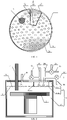
- the high-throughput vapor deposition apparatus includes: a reaction chamber 1; a rotary workbench 2, which is located in the reaction chamber 1, used to support a substrate (not shown) and drive the substrate to rotate; a gas introduction device 3, which is located in the reaction chamber 1 and above the rotary workbench 2, and spaced from the rotary workbench 2 by a distance, wherein the gas introduction device 3 divides the reaction chamber 1 into an upper chamber 11 and a lower chamber 12, and a plurality of through holes 31 is provided on the gas introduction device 3, where the through holes 31 bring the upper chamber 11 and the lower chamber 12 into communication; a gas isolation structure 4,which is located in the upper chamber 11, and divides the upper chamber 11 into an isolation gas chamber 111 and a reaction gas chamber 112 which are isolated from each other, wherein a center of the gas introduction device 3 is located outside the reaction gas chamber 112, and the plurality of through holes 31 respectively allows the isolation gas chamber
- the high-throughput vapor deposition apparatus of the present invention only requires one isolation gas supply system and one reaction gas isolation system, a total of two systems, and thus is simple in structure, easy to implement, and good in isolation.
- the high-throughput vapor deposition apparatus of the present invention has high degree of integration, in which other devices, for example, a real-time measurement device, can be integrated so that the function is more complete.
- the rotary workbench 2 is connected to a driving device (not shown), and the rotary workbench 2 is driven by the driving device to rotate when in needs.
- the plurality of through holes 31 can be evenly distributed on the gas introduction device 3.
- the distribution density of the through holes 31 corresponding to an area of the isolation gas chamber 111 where is adjacent to the reaction gas chamber 112 is greater than that corresponding to other areas of the isolation gas chamber 111.
- the distribution density of the through holes 31 corresponding to an area of the isolation gas chamber 111 where is adjacent to the reaction gas chamber 112 allows the isolation gas to form a gas curtain with better isolation effect, thus preventing the deposition of the reaction gas in other areas of the substrate.
- the shape and size of the gas introduction device 3 are the same as the internal shape and size of the reaction chamber 1, so that the sides of the gas introduction device 3 are in contact with the inner walls of the reaction chamber 1, to ensure that the upper chamber 11 and the lower chamber 12 communicate only through the through holes 31.
- the area of the reaction gas chamber 112 at the bottom is smaller than the area of the isolation gas chamber 111 at the bottom.
- the center of the gas introduction device 3 corresponds to the center of the rotary workbench 2 in a vertical direction. Since the center of the gas introduction device 3 is located outside the reaction gas chamber 112 and the center of the gas introduction device 3 corresponds to the center of the rotary workbench 2 in a vertical direction, the rotary workbench can be rotated to perform thin film deposition in different areas of the substrate when thin film deposition is carried out.
- the gas isolation structure 4 includes: a first gas isolation plate 41, which has one end in contact with an inner wall of the reaction chamber 1, and the other end extending into the upper chamber 11; a second gas isolation plate 42, which has one end in contact with an inner wall of the reaction chamber 1, and the other end extending into the upper chamber 11, wherein the second gas isolation plate 42 is spaced from the first gas isolation plate 41 by a distance; and a third gas isolation plate 43, which has one end connected to one end of the first gas isolation plate 41 away from the inner wall of the reaction chamber 1, and the other end connected to one end of the second gas isolation plate 42 away from the inner wall of the reaction chamber 1, wherein the height of the first gas isolation plate 41, the height of the second gas isolation plate 42 and the height of the third gas isolation plate 43 are all the same as the distance from an upper surface of the gas introduction device 3 to the top of the reaction chamber 1.
- the gas isolation structure 4 includes an arc-shaped gas isolation plate (not shown), whose two ends are both connected to the interior of the reaction chamber 1, and the height of the arc-shaped gas isolation plate is the same as the distance from the upper surface of the gas introduction device 3 to the top of the reaction chamber 1.
- the high-throughput vapor deposition apparatus may further include an isolation gas supply system (not shown), which is connected to the isolation gas introduction channel 5, and used to supply an isolation gas to the isolation gas chamber 111; and a reaction gas supply system (not shown), which is connected to the reaction gas introduction channel 6, and used to supply a reaction gas into the reaction gas chamber 112.
- an isolation gas supply system (not shown) which is connected to the isolation gas introduction channel 5, and used to supply an isolation gas to the isolation gas chamber 111
- a reaction gas supply system (not shown), which is connected to the reaction gas introduction channel 6, and used to supply a reaction gas into the reaction gas chamber 112.
- the isolation gas supply system can include an isolation gas source (not shown) and a first supply pipe 81.
- the first supply pipe 81 has one end connected to the isolation gas source, and the other end connected to the isolation gas introduction channel 5.
- the isolation gas provided by the isolation gas supply system to the isolation gas chamber 111 may include, but is not limited to, argon (Ar).
- the reaction gas supply system may include a carrier gas source (not shown), a precursor source (not shown), a reaction gas source, a second supply pipe 82, a third supply pipe 83, a fourth supply pipe 85, a sixth supply pipe 86, a seventh supply pipe 87, and an eighth supply pipe 88.
- One end of both the third supply pipe 83 and the fourth supply pipe 84 is connected to the carrier gas source, and the other end is connected to the reaction gas introduction channel 6.
- One end of the second supply pipe is connected to the reaction gas source, and the other end communicates with the third supply pipe 83.
- One end of the sixth supply pipe 86 is connected to the precursor source, and the other end communicates with the fourth supply pipe 84.
- One end of the fifth supply pipe 85 is connected to the carrier gas source, and the other end communicates with the sixth supply pipe 86.
- One end of the seventh supply pipe 87 is connected to another carrier gas source, and the other end communicates with the fourth supply pipe 84.
- One end of the eighth supply pipe 88 is connected to the carrier gas source, and the other end communicates with the seventh supply pipe 84.
- the reaction gas supply system is used to supply the reaction gas and the reaction precursor to the reaction gas chamber 112 with the assistance of the carrier gas.
- the high-throughput vapor deposition apparatus further includes a real-time measurement device 7.
- the real-time measurement device 7 is used to characterize, without limitation, the element composition, film thickness, and microstructure of a film deposited on an upper surface of the substrate, wherein an active end of the real-time measurement device 7 is located in the reaction chamber 1, and between the rotary workbench 2 and the gas introduction device 3.
- the real-time measurement device 9 may include, but is not limited to, an Auger Electron Spectrometer (AES).
- AES Auger Electron Spectrometer
- the working principle of the high-throughput vapor deposition apparatus in this embodiment is as follows.
- a first deposition area of the substrate is driven by the rotary workbench 2 to rotate to right below the reaction gas chamber 112.
- the reaction gas supply system provides the reaction gas and the reaction precursor to the reaction gas chamber 112, and the isolation gas supply system provides the isolation gas to the isolation gas chamber 111 at the same time.
- the isolation gas enters the lower chamber 12 through the through holes 31 to form an isolation gas curtain.
- the reaction gas and the reaction precursor enter the lower chamber 12 through the through holes 31. Due to the barrier of the gas curtain formed by the insulation gas, the reaction gas and the reaction precursor can only undergo thin film deposition in the first deposition area of the substrate that is located right under the reaction gas chamber 112.
- a second deposition area of the substrate is driven by the rotary workbench 2 to rotate to right below the reaction gas chamber 112 for carrying out thin film deposition in the second deposition area.
- the above steps are repeated, until the thin film deposition process is completed. In this way, thin film deposition can be performed in different areas of the substrate.
- the high-throughput vapor deposition apparatus of the present invention only requires one isolation gas supply system and one reaction gas isolation system, a total of two systems, and thus is simple in structure, easy to implement, and good in isolation.
- the high-throughput vapor deposition apparatus of the present invention has high degree of integration, in which other devices, for example, a real-time measurement device, can be integrated so that the function is more complete.
- the present invention provides a vapor deposition method, which includes the following steps:
- Step 1) referring to S1 in Fig. 3 in connection with Figs. 1 and 2 , a high-throughput vapor deposition apparatus as described in embodiment 1 is provided. Specific structure of the high-throughput vapor deposition apparatus can be made reference in Embodiment 1, and is not repeated here again.
- Step 2 Referring to Fig. 3 in connection with Figs. 1 and 2 , an isolation gas is introduced into the isolation gas chamber 111 via the isolation gas introduction channel 5, and a reaction gas is introduced into the reaction gas chamber 112 via the reaction gas introduction channel 6, for carrying out thin film deposition on an area of the substrate corresponding to the reaction gas chamber 112 (for example, the first deposition area in Embodiment 1).
- reaction gas when the reaction gas is introduced into the reaction gas chamber 112, a reaction precursor can also be introduced into the reaction gas chamber 112 at the same time.
- the isolation gas introduced into the isolation gas chamber 111 enters the lower chamber 12 via the through holes 31 to form a gas curtain, and the reaction gas and the reaction precursor enter the lower chamber 12 through the through holes 31. Due to the barrier of the gas curtain formed by the insulation gas, the reaction gas and the reaction precursor can only undergo thin film deposition in an area of the substrate that is located right under the reaction gas chamber 112.
- Step 3 referring to S3 in Fig. 3 in connection with Figs. 1 and 2 , the substrate is driven by the rotary workbench 2 to rotate by a preset angle, so that an area of the substrate where thin film deposition is not carried out (such as a second deposition area in Embodiment 1) is rotated to directly below the reaction gas chamber 112, for carrying out thin film deposition on the area of a substrate corresponding to the reaction gas chamber 112.
- an area of the substrate where thin film deposition is not carried out such as a second deposition area in Embodiment 1
- Step 4 referring to S4 in Fig. 3 in connection with Figs. 1 and 2 , Step 3) is repeated at least once, to carry out thin film deposition on a plurality of different areas of the substrate respectively.
- the present invention provides a high-throughput vapor deposition apparatus and a vapor deposition method.
- the high-throughput vapor deposition apparatus includes: a reaction chamber; a rotary workbench, located in the reaction chamber and used to support a substrate and drive the substrate to rotate; a gas introduction device, located in the reaction chamber and above the rotary workbench, and spaced from the rotary workbench by a distance, wherein the gas introduction device divides the reaction chamber into an upper chamber and a lower chamber, and a plurality of through holes is provided on the gas introduction device, and the through holes bring the upper chamber and the lower chamber into communication; a gas isolation structure, located in the upper chamber, and dividing the upper chamber into an isolation gas chamber and a reaction gas chamber which are isolated from each other, wherein a center of the gas introduction device is located outside the reaction gas chamber, and the plurality of through holes respectively allows the isolation gas chamber and the reaction gas chamber to communicate with the lower chamber; an isolation gas introduction channel, located on a wall of the reaction chamber and communicating with
- the high-throughput vapor deposition apparatus of the present invention only requires one isolation gas supply system and one reaction gas isolation system, a total of two systems, and thus is simple in structure, easy to implement, and good in isolation.
- the high-throughput vapor deposition apparatus of the present invention has high degree of integration, in which other devices, for example, a real-time measurement device, can be integrated so that the function is more complete.
Landscapes
- Chemical & Material Sciences (AREA)
- General Chemical & Material Sciences (AREA)
- Chemical Kinetics & Catalysis (AREA)
- Engineering & Computer Science (AREA)
- Materials Engineering (AREA)
- Mechanical Engineering (AREA)
- Metallurgy (AREA)
- Organic Chemistry (AREA)
- Chemical Vapour Deposition (AREA)
Applications Claiming Priority (2)
| Application Number | Priority Date | Filing Date | Title |
|---|---|---|---|
| CN201910759403.7A CN110408910B (zh) | 2019-08-16 | 2019-08-16 | 高通量气相沉积设备及气相沉积方法 |
| PCT/CN2019/119929 WO2021031425A1 (zh) | 2019-08-16 | 2019-11-21 | 高通量气相沉积设备及气相沉积方法 |
Publications (2)
| Publication Number | Publication Date |
|---|---|
| EP4001457A1 true EP4001457A1 (de) | 2022-05-25 |
| EP4001457A4 EP4001457A4 (de) | 2023-08-16 |
Family
ID=68367572
Family Applications (1)
| Application Number | Title | Priority Date | Filing Date |
|---|---|---|---|
| EP19941890.6A Pending EP4001457A4 (de) | 2019-08-16 | 2019-11-21 | Vorrichtung und verfahren zur dampfabscheidung mit hohem durchsatz |
Country Status (6)
| Country | Link |
|---|---|
| US (1) | US12209311B2 (de) |
| EP (1) | EP4001457A4 (de) |
| JP (1) | JP7398549B2 (de) |
| KR (1) | KR102776796B1 (de) |
| CN (1) | CN110408910B (de) |
| WO (1) | WO2021031425A1 (de) |
Families Citing this family (4)
| Publication number | Priority date | Publication date | Assignee | Title |
|---|---|---|---|---|
| CN110408910B (zh) | 2019-08-16 | 2020-08-28 | 中国科学院上海微系统与信息技术研究所 | 高通量气相沉积设备及气相沉积方法 |
| CN116770222B (zh) * | 2022-03-09 | 2024-08-06 | 上海集成电路材料研究院有限公司 | 一种高通量薄膜沉积设备、刻蚀设备及其方法 |
| EP4484606A1 (de) * | 2022-03-09 | 2025-01-01 | Shanghai Institute of IC Materials | Vorrichtung zur abscheidung von dünnschichten mit hohem durchsatz, ätzvorrichtung und ätzverfahren |
| KR200498277Y1 (ko) | 2024-03-11 | 2024-08-23 | 안혜연 | 다기능 초간편 드라이버 골프티 어셈블리 |
Family Cites Families (24)
| Publication number | Priority date | Publication date | Assignee | Title |
|---|---|---|---|---|
| JPS6294942A (ja) | 1985-10-21 | 1987-05-01 | Nec Corp | 薄膜の製造方法 |
| JPS6311672A (ja) | 1986-06-30 | 1988-01-19 | Nec Corp | 薄膜形成方法 |
| JP4090347B2 (ja) * | 2002-03-18 | 2008-05-28 | 株式会社日立国際電気 | 半導体装置の製造方法及び基板処理装置 |
| KR100821810B1 (ko) * | 2002-11-08 | 2008-04-11 | 도꾸리쯔교세이호진 상교기쥬쯔 소고겡뀨죠 | 기판상의 막형성 방법 |
| DE10320597A1 (de) * | 2003-04-30 | 2004-12-02 | Aixtron Ag | Verfahren und Vorrichtung zum Abscheiden von Halbleiterschichten mit zwei Prozessgasen, von denen das eine vorkonditioniert ist |
| DE102005055468A1 (de) | 2005-11-22 | 2007-05-24 | Aixtron Ag | Verfahren zum Abscheiden von Schichten in einem CVD-Reaktor sowie Gaseinlassorgan für einen CVD-Reaktor |
| US7871828B2 (en) * | 2007-02-06 | 2011-01-18 | Applied Materials, Inc. | In-situ dose monitoring using optical emission spectroscopy |
| JP4699545B2 (ja) | 2009-07-06 | 2011-06-15 | シャープ株式会社 | 気相成長装置及び気相成長方法 |
| JP5445252B2 (ja) | 2010-03-16 | 2014-03-19 | 東京エレクトロン株式会社 | 成膜装置 |
| CN101962751B (zh) | 2010-10-27 | 2012-02-22 | 普尼太阳能(杭州)有限公司 | 一种多步物理气相沉积设备 |
| CN102127757A (zh) | 2011-01-14 | 2011-07-20 | 映瑞光电科技(上海)有限公司 | Mocvd反应系统 |
| US9175391B2 (en) | 2011-05-26 | 2015-11-03 | Intermolecular, Inc. | Apparatus and method for combinatorial gas distribution through a multi-zoned showerhead |
| US20120315396A1 (en) * | 2011-06-13 | 2012-12-13 | Intermolecular, Inc. | Apparatus and method for combinatorial plasma distribution through a multi-zoned showerhead |
| CN103014846A (zh) * | 2013-01-14 | 2013-04-03 | 东莞市中镓半导体科技有限公司 | 一种材料气相外延用同心圆环喷头结构 |
| TWI683382B (zh) | 2013-03-15 | 2020-01-21 | 應用材料股份有限公司 | 具有光學測量的旋轉氣體分配組件 |
| US9087864B2 (en) * | 2013-12-19 | 2015-07-21 | Intermolecular, Inc. | Multipurpose combinatorial vapor phase deposition chamber |
| JP2016148080A (ja) | 2015-02-12 | 2016-08-18 | 株式会社日立国際電気 | 基板処理装置、半導体装置の製造方法およびプログラム |
| US10954597B2 (en) * | 2015-03-17 | 2021-03-23 | Asm Ip Holding B.V. | Atomic layer deposition apparatus |
| CN106158569B (zh) | 2015-03-26 | 2018-08-07 | 理想晶延半导体设备(上海)有限公司 | 半导体处理设备 |
| KR102462931B1 (ko) | 2015-10-30 | 2022-11-04 | 삼성전자주식회사 | 가스 공급 유닛 및 기판 처리 장치 |
| KR102625420B1 (ko) | 2016-05-27 | 2024-01-16 | 에이에스엠 아이피 홀딩 비.브이. | 반도체 웨이퍼 처리 장치 |
| US10246775B2 (en) | 2016-08-03 | 2019-04-02 | Tokyo Electron Limited | Film forming apparatus, method of forming film, and storage medium |
| JP6836965B2 (ja) * | 2017-06-23 | 2021-03-03 | 昭和電工株式会社 | 成膜装置 |
| CN110408910B (zh) | 2019-08-16 | 2020-08-28 | 中国科学院上海微系统与信息技术研究所 | 高通量气相沉积设备及气相沉积方法 |
-
2019
- 2019-08-16 CN CN201910759403.7A patent/CN110408910B/zh active Active
- 2019-11-21 EP EP19941890.6A patent/EP4001457A4/de active Pending
- 2019-11-21 JP JP2022510171A patent/JP7398549B2/ja active Active
- 2019-11-21 KR KR1020227008811A patent/KR102776796B1/ko active Active
- 2019-11-21 US US17/635,389 patent/US12209311B2/en active Active
- 2019-11-21 WO PCT/CN2019/119929 patent/WO2021031425A1/zh not_active Ceased
Also Published As
| Publication number | Publication date |
|---|---|
| US12209311B2 (en) | 2025-01-28 |
| CN110408910B (zh) | 2020-08-28 |
| EP4001457A4 (de) | 2023-08-16 |
| KR20220046670A (ko) | 2022-04-14 |
| US20220290298A1 (en) | 2022-09-15 |
| CN110408910A (zh) | 2019-11-05 |
| KR102776796B1 (ko) | 2025-03-05 |
| WO2021031425A1 (zh) | 2021-02-25 |
| JP2022545076A (ja) | 2022-10-25 |
| JP7398549B2 (ja) | 2023-12-14 |
Similar Documents
| Publication | Publication Date | Title |
|---|---|---|
| EP4001457A1 (de) | Vorrichtung und verfahren zur dampfabscheidung mit hohem durchsatz | |
| US10604847B2 (en) | Gas distribution system, reactor including the system, and methods of using the same | |
| CN101842873B (zh) | 基于蒸气的组合式处理 | |
| US20190385823A1 (en) | Chemical control features in wafer process equipment | |
| CN103797155B (zh) | 用于直线型大面积等离子体反应器中均匀处理的气体输送和分配 | |
| EP1774057B1 (de) | Vorrichtung und verfahren zur chemischen gasphasenabscheidung mit hohem durchsatz | |
| CN101058872A (zh) | 用于半导体工艺件处理反应器的气体分布装置及其反应器 | |
| CN108546931B (zh) | 基板处理设备 | |
| US20160244876A1 (en) | Gas injector and cover plate assembly for semiconductor equipment | |
| US11293097B2 (en) | Apparatus for distributing gas and apparatus for processing substrate including the same | |
| TW201204865A (en) | Vertical inline CVD system | |
| CN103866288B (zh) | 一种用于原子层薄膜沉积的反应装置及方法 | |
| CN104947083A (zh) | 基板处理装置 | |
| TW201618215A (zh) | 用於在一基板上成長二元、三元及四元材料之方法與系統 | |
| JP2025527920A (ja) | シャワープレート、シャワー方法及び処理装置 | |
| CN101770932B (zh) | 等离子体处理设备 | |
| CN101871099A (zh) | 通过气体分散器的等离子体均匀度控制 | |
| CN101310043B (zh) | 原子层沉积反应器 | |
| WO2024055142A1 (en) | Gas supply apparatus and substrate processing apparatus including the same | |
| DE102012104475A1 (de) | Carousel-Reactor | |
| JP2003160875A (ja) | Cvd装置 | |
| TWI585232B (zh) | 線性電漿輔助化學氣相沈積設備 | |
| US9605345B2 (en) | Vertical furnace for improving wafer uniformity | |
| CN103215568A (zh) | 气体供给头和基板处理装置 | |
| JP2765371B2 (ja) | 成膜処理装置 |
Legal Events
| Date | Code | Title | Description |
|---|---|---|---|
| STAA | Information on the status of an ep patent application or granted ep patent |
Free format text: STATUS: THE INTERNATIONAL PUBLICATION HAS BEEN MADE |
|
| PUAI | Public reference made under article 153(3) epc to a published international application that has entered the european phase |
Free format text: ORIGINAL CODE: 0009012 |
|
| STAA | Information on the status of an ep patent application or granted ep patent |
Free format text: STATUS: REQUEST FOR EXAMINATION WAS MADE |
|
| 17P | Request for examination filed |
Effective date: 20220218 |
|
| AK | Designated contracting states |
Kind code of ref document: A1 Designated state(s): AL AT BE BG CH CY CZ DE DK EE ES FI FR GB GR HR HU IE IS IT LI LT LU LV MC MK MT NL NO PL PT RO RS SE SI SK SM TR |
|
| DAV | Request for validation of the european patent (deleted) | ||
| DAX | Request for extension of the european patent (deleted) | ||
| A4 | Supplementary search report drawn up and despatched |
Effective date: 20230719 |
|
| RIC1 | Information provided on ipc code assigned before grant |
Ipc: C23C 16/455 20060101ALI20230713BHEP Ipc: C23C 16/52 20060101ALI20230713BHEP Ipc: C23C 16/04 20060101ALI20230713BHEP Ipc: C23C 16/458 20060101ALI20230713BHEP Ipc: C23C 16/44 20060101AFI20230713BHEP |