EP4001478B1 - Vliesleger für ein kardenvlies und dazugehöriges verfahren - Google Patents
Vliesleger für ein kardenvlies und dazugehöriges verfahren Download PDFInfo
- Publication number
- EP4001478B1 EP4001478B1 EP21207234.2A EP21207234A EP4001478B1 EP 4001478 B1 EP4001478 B1 EP 4001478B1 EP 21207234 A EP21207234 A EP 21207234A EP 4001478 B1 EP4001478 B1 EP 4001478B1
- Authority
- EP
- European Patent Office
- Prior art keywords
- conveyor belt
- distributor
- cylinder
- crosslapper
- carriage
- Prior art date
- Legal status (The legal status is an assumption and is not a legal conclusion. Google has not performed a legal analysis and makes no representation as to the accuracy of the status listed.)
- Active
Links
Images




Classifications
-
- D—TEXTILES; PAPER
- D01—NATURAL OR MAN-MADE THREADS OR FIBRES; SPINNING
- D01G—PRELIMINARY TREATMENT OF FIBRES, e.g. FOR SPINNING
- D01G25/00—Lap-forming devices not integral with machines specified above
-
- D—TEXTILES; PAPER
- D04—BRAIDING; LACE-MAKING; KNITTING; TRIMMINGS; NON-WOVEN FABRICS
- D04H—MAKING TEXTILE FABRICS, e.g. FROM FIBRES OR FILAMENTARY MATERIAL; FABRICS MADE BY SUCH PROCESSES OR APPARATUS, e.g. FELTS, NON-WOVEN FABRICS; COTTON-WOOL; WADDING ; NON-WOVEN FABRICS FROM STAPLE FIBRES, FILAMENTS OR YARNS, BONDED WITH AT LEAST ONE WEB-LIKE MATERIAL DURING THEIR CONSOLIDATION
- D04H1/00—Non-woven fabrics formed wholly or mainly of staple fibres or like relatively short fibres
- D04H1/70—Non-woven fabrics formed wholly or mainly of staple fibres or like relatively short fibres characterised by the method of forming fleeces or layers, e.g. reorientation of fibres
- D04H1/72—Non-woven fabrics formed wholly or mainly of staple fibres or like relatively short fibres characterised by the method of forming fleeces or layers, e.g. reorientation of fibres the fibres being randomly arranged
- D04H1/736—Non-woven fabrics formed wholly or mainly of staple fibres or like relatively short fibres characterised by the method of forming fleeces or layers, e.g. reorientation of fibres the fibres being randomly arranged characterised by the apparatus for arranging fibres
-
- D—TEXTILES; PAPER
- D04—BRAIDING; LACE-MAKING; KNITTING; TRIMMINGS; NON-WOVEN FABRICS
- D04H—MAKING TEXTILE FABRICS, e.g. FROM FIBRES OR FILAMENTARY MATERIAL; FABRICS MADE BY SUCH PROCESSES OR APPARATUS, e.g. FELTS, NON-WOVEN FABRICS; COTTON-WOOL; WADDING ; NON-WOVEN FABRICS FROM STAPLE FIBRES, FILAMENTS OR YARNS, BONDED WITH AT LEAST ONE WEB-LIKE MATERIAL DURING THEIR CONSOLIDATION
- D04H1/00—Non-woven fabrics formed wholly or mainly of staple fibres or like relatively short fibres
- D04H1/70—Non-woven fabrics formed wholly or mainly of staple fibres or like relatively short fibres characterised by the method of forming fleeces or layers, e.g. reorientation of fibres
- D04H1/74—Non-woven fabrics formed wholly or mainly of staple fibres or like relatively short fibres characterised by the method of forming fleeces or layers, e.g. reorientation of fibres the fibres being orientated, e.g. in parallel (anisotropic fleeces)
Definitions
- the present invention relates to a machine for crosslapping card webs, also referred to as crosslapper for card webs, in accordance with the preamble of claim 1.
- a crosslapper for a card web and a method for crosslapping a card web.
- the crosslapper of the present invention can be used in a textile production line, included at the exit of a carding plant, e.g. a line for processing fibres to be used for manufacturing semifinished products, commonly referred to as non-woven fabrics, or simply as nonwovens, to be subsequently used in many applications.
- Nonwovens are obtained by processing fibres, generally synthetic ones, in carding machines.
- Carding machines for nonwoven production process the fibres to produce a web formed by the cohesion of the fibres themselves.
- the strength properties of such a web are insufficient for use in many fields, and therefore thicker webs are produced, having better mechanical strength properties, by coupling multiple webs together by layering.
- Such coupling by layering is effected directly at the exit of the carding plant by subjecting the web to a crosslapping action that causes the web exiting the carding machine to be overlapped into multiple layers.
- the crosslapping action is performed by a machine called crosslapper.
- Current crosslappers e.g.
- Document EP 0786545 A2 discloses a machine to form carded webs.
- the machine has a system of continuous belts and trolleys.
- the belts are close together to carry the web at the upper channel between the first two belts to the lower channel across the first trolley, which is also defined by the first two belts to deliver the web to a conveyor.
- Document EP 1010787 A2 describes an assembly to lay the webs from a carding machine, in laying widths, having a delivery belt, several main trolleys and two continuous conveyor belts over the main trolleys.
- At least one support trolley supports a conveyor belt level with a number of deflection rollers for the conveyor belt levels.
- the belt entry and exit are generally at the same height level.
- At least three deflection rollers have their axes on a triangle or a polygon, forming an omega-shaped guide for the lower levels of both conveyor belts.
- the web layer has two support trolleys, each at a lower belt level of the two conveyor belts.
- the web layer has at least one self-standing and mobile support trolley, near the lower main trolley, with a drive link to the upper main trolley.
- the web layer has a support trolley, which is integrated with the upper main trolley.
- the web layer has at least one mobile tensioner trolley for at least one conveyor belt, with a drive link to at least one of the main trolleys.
- the assembly can have at least one additional self-standing support trolley, at one of the belt tensioner trolleys, with a drive link to a main trolley.
- a first drawback is related to the asymmetric motion of the conveyor belts. This implies less tension in the web, which, prior to entering the unloading cylinders, is dropped (or abandoned) in a downward section, the angle of which varies according to the crosslapper type and/or configuration.
- a further drawback comes from the necessity of reducing the speed of the crosslapping operation in order to be able to better control the inertia effects of the abandoned web while reversing the motion of the layering carriage.
- Another problem relates to the need to remove the most dense parts from the mat, and keep only the most homogeneous part of the mat.
- a trimming step consists of removing the side edges of the mat exiting the crosslapper wherever the density of the mat is different (generally higher) than in the central area of the same.
- the edges need to be trimmed by a width of approximately 10 to 15 cm per side: this results in a total scrap amount of 20-30 cm, which, considering an average mat width of 400 cm, is 6% on average.
- the invention described herein consists of a crosslapper and a related crosslapping method that comply with two antithetical operating constraints, i.e.: the card web must be fed in at a constant speed, equal to its speed as it exits the carding machine; the material cannot exit at a constant speed, since the layering carriage must necessarily move in a reciprocating manner in order to deposit the various layers.
- the principle of operation of the present invention is based on a symmetric structure in which one carriage slides within two looped conveyor belts, commonly called tables, while ensuring a constant tension of the card web.
- FIG. 1 there is schematically shown a crosslapper 100 for a card web 101 according to one embodiment of the present invention.
- the crosslapper 100 can be installed downstream of a carding machine in a textile production line.
- the crosslapper 100 may be inserted in new carding lines or, alternatively, with just a few adaptations, in existing carding lines as a replacement for current crosslappers, thus improving the performance of existing plants.
- the carding machine outputs a card web 101, which may be, for example, a non-woven web.
- the card web 101 exiting the carding machine at a constant speed is fed into the crosslapper 100 by means of, for example, at least one feeding rotary cylinder 133.
- Said crosslapper 100 for a card web 101 comprises a first conveyor belt 110 and a second conveyor belt 120, both arranged in a closed-loop configuration.
- Said conveyor belts are configured to overlap each other in at least one conveyor belt portion and are adapted to define a conveyance channel 105 for said card web 101. In this manner, an inlet zone 106 and an outlet zone 107 for said web card 101 are defined in the conveyance channel 105.
- Said first conveyor belt 110 and second conveyor belt 120 are made of substantially inextensible materials, e.g. canvas rubber and/or metal-core rubber, and can be wound, even only partially, on fixed and/or self-moving rotary cylinders (or rollers), which are in turn supported by the structure of the crosslapper 100, e.g.
- the rotary cylinders make it possible to move said first conveyor belt 110 and second conveyor belt 120 inside the crosslapper 100 and may be free to rotate and/or may be driven by actuator means, e.g. electric motors and/or electrovalves.
- the actuator means are coupled to said rotary cylinders via coupling means, e.g. belts, arms, pistons and/or pulleys.
- the position and trim of one or more rotary cylinders inside the crosslapper 100 can be modified via said actuator means and coupling means, e.g. arms operated by electric motors or pistons controlled by means of electrovalves.
- the crosslapper 100 may further comprise sensor means for detecting the position of its moving parts, or other types of sensor means adapted to monitor production quality and/or quantity, e.g. sensors measuring the speed of the card web 101 and/or of said first conveyor belt 110 and second conveyor belt 120.
- the crosslapper 100 is provided with a control unit 150 adapted to control the actuator means of the crosslapper 100 and adapted to receive data from the sensor means of the crosslapper 100.
- the control unit 150 may comprise a processing module, a memory module, an input/output module, a communication module, an interface module and one or more buses mutually connecting said modules; said control unit 150 may be, for example, a PLC, an axis control system or a computer.
- the memory module may consist of an electronic memory like, for example, a solid-state flash memory, which stores information and instructions implementing the present embodiment of the invention. Such information may concern, for example, the position and the revolution speed of the rotary cylinders.
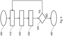
- the instructions stored in the memory module will be described in detail later on with reference to the flow chart of Figure 4 .
- the processing module is constructed by using electric components such as, for example, microcontrollers or processors with an ARM architecture.
- the processing module processes the information and the instructions stored in the memory module.
- the input/output module handles, respectively, the input devices, e.g. the sensor means, and the output devices, e.g. the actuator means.
- the interface module allows users and/or service technicians to interface with the crosslapper 100 in order to control its functions and/or verify its operating state.
- the communication module provides communication with a remote management system for managing the crosslapper 100 and/or the textile production plant in which the crosslapper 100 is included.
- Said communication module may comprise, for example, a Wi-Fi, GSM or ETHERNET module. Therefore, connections to the remote management system are available both in wired and wireless mode.
- the crosslapper 100 can interact with the other machines normally included in the textile production cycle via sensor means adapted to detect parameters that, after having been appropriately processed, make it possible to improve the evenness of the product exiting the carding machine and during the next processing steps, e.g. needle looming, quilting, calendering, etc.
- the crosslapper 100 arranged upstream of needle looming machines along the textile production line, may comprise sensor means adapted to measure the thickness, and hence the density, of the final material exiting the needle looms throughout its width; said sensor means may be, for example, optical or X-ray scanners.
- This will allow the control unit to change, whether on average and/or locally, the density value of the layered material according to the speed of motion of the moving components of the crosslapper 100, such as, for example, the rotary cylinders or the moving carriage 180, which will be described in greater detail below.
- Said crosslapper 100 comprises a collection surface 190 adapted to collect said layered card web 101, a distributor carriage 180, and may comprise first retriever means 160 and second retriever means 170.
- Said first retriever means 160 comprise at least one first rotary cylinder 131, whereon the first conveyor belt 110 is at least partly wound.
- Said at least one first rotary cylinder 131 is adapted to create one or more mobile loops 141 of the first conveyor belt 110, thus allowing it to be moved under tension.
- one or more mobile loops 141 of the first conveyor belt 110 can be formed within the crosslapper 100.
- the extension (width) of said loops along a predetermined direction can be determined with respect to at least one fixed or self-moving element comprised in the crosslapper 100, such as, for example, a pin or another rotary cylinder whereon said first conveyor belt 110 is at least partly wound.
- the retriever means 160 comprising components like rotary cylinders, pins and the like, permit adjusting the extension of the first conveyor belt 110 inside the crosslapper 100, thereby causing it to be subj ected to an appropriate pull/tension, so that the card web 101 will be appropriately moved under tension to ensure a correct crosslapping process, as described by the present invention.
- the first rotary cylinder 131 may be operatively connected to a first actuator 171a and to a second actuator 171b adapted to tightly move the first conveyor belt 110 during the motion of the distributor carriage 180.
- the first actuator 171a may be operatively connected to a first end of the first rotary cylinder 131
- the second actuator 171b may be operatively connected to a second end of the first rotary cylinder 131, so as to move the first rotary cylinder 131 in an independent manner.
- the first actuator 171a and the second actuator 171b may be electric linear actuators, e.g.
- first actuator 171a and the second actuator 171b may be adapted to move the first conveyor belt 110 along a first direction orthogonal to the sliding direction of the first conveyor belt 110, so as to prevent the first conveyor belt 110 from rubbing against the structure of the crosslapper 100.
- the first conveyor belt 110 can be moved along the first orthogonal direction, which may be coplanar with the first conveyor belt 110 itself, under a first differential force D1 that can be added to the first average force F1.
- the crosslapper 100 allows centering the first conveyor belt 110 without requiring the use of pneumatic centering units like those that are present on prior-art crosslappers.
- Said second retriever means 170 comprise at least one second rotary cylinder 132 whereon said second conveyor belt 120 is wound, said at least one second rotary cylinder 132 being adapted to create one or more mobile loops 142 of said second conveyor belt 120 for tightly moving said second conveyor belt 120.
- the second conveyor belt 120 passes on at least one second rotary cylinder 132, one or more mobile loops 142 of the second conveyor belt 120 can be formed within the crosslapper 100.
- the extension (width) of said loops along a predetermined direction can be determined with respect to at least one fixed or self-moving element comprised in the crosslapper 100, such as, for example, a pin or another rotary cylinder whereon said second conveyor belt 120 is at least partly wound.
- the retriever means 170 comprising components like rotary cylinders, pins and the like, permit adjusting the extension of the second conveyor belt 120 inside the crosslapper 100, thereby causing it to be subjected to an appropriate pull/tension, so that the card web 101 will be appropriately moved under tension to ensure a correct crosslapping process, as described by the present invention.
- the number of mobile loops of said first conveyor belt 110 and said second conveyor belt 120 and their respective widths contribute to determining the correct feeding of the card web 101 in the conveyance channel 105.
- the second rotary cylinder 132 may be operatively connected to a third actuator 172a and to a fourth actuator 172b adapted to tightly move the second conveyor belt 120 during the motion of the distributor carriage 180.
- the third actuator 172a may be operatively connected to a first end of the second rotary cylinder 132, while the fourth actuator 172b may be operatively connected to a second end of the second rotary cylinder 132, so as to move the second rotary cylinder 132 in an independent manner.
- the third actuator 172a and the fourth actuator 172b may be adapted to move the second conveyor belt 120 along a second direction orthogonal to the sliding direction of the second conveyor belt 120, so as to prevent the second conveyor belt 120 from rubbing against the structure of the crosslapper 100.
- the second conveyor belt 120 can be moved along the second orthogonal direction, which may be coplanar with the second conveyor belt 120 itself, under a second differential force D2 that can be added to the second average force F2.
- the crosslapper 100 allows centering the second conveyor belt 120 without requiring the use of pneumatic centering units like those that are present on prior-art crosslappers.
- FIG 2 schematically shows a detail of the crosslapper 100 of Figure 1 , i.e. the distributor carriage 180, according to the present embodiment of the invention.
- Said distributor carriage 180 comprises at least one first distributor cylinder 181, whereon said first conveyor belt 110 slides, and at least one second distributor cylinder 182, whereon said second conveyor belt 120 slides.
- Said first distributor cylinder 181 and second distributor cylinder 182 define said outlet zone 107 for the card web 101.
- the distributor carriage 180 is adapted to move parallel to the collection surface 190 for depositing thereon the card web 101 in successive layers to form the mat.
- the card web 101 is fed into the crosslapper 100, e.g. by means of at least one inlet rotary cylinder 133 (shown in Figure 1 ) and is then transported, e.g. by means of the second conveyor belt 120, towards the distributor carriage 180.
- the card web 101 enters the conveyance channel 105 through the inlet zone 106 and exits the distributor carriage 180 through the outlet zone 107.
- the distributor carriage 180 deposits the card web 101 in successive layers onto said collection surface 190 to form the mat.
- Said distributor carriage 180 comprises at least one third distributor cylinder 183, whereon said first conveyor belt 110 is wound, and at least one fourth distributor cylinder 184, whereon said second conveyor belt 120 is wound.
- Said third distributor cylinder 183 and fourth distributor cylinder 184 are adapted to create one or more mobile loops 143 defined in at least one portion of said conveyance channel 105 for the card web 101, positioned between said inlet zone 106 and outlet zone 107 by the distributor carriage 180. This technical measure advantageously makes it possible to accumulate the card web 101 during the motion of the distributor carriage 180.
- FIG. 3a, 3b and 3c there is schematically shown the principle of operation of the crosslapper 100 according to the embodiment of the invention of Figure 1 , in three operating configurations thereof, respectively.
- the principle of operation of the present invention is based on a symmetric structure of the crosslapper 100 (i.e. a so-called "accordion" structure), wherein the distributor carriage 180 slides through said first conveyor belt 110 and second conveyor belt 120, commonly referred to as tables.
- the two tables always have a specular behaviour: when the first table becomes longer, the second table becomes shorter, and vice versa.
- the lengthening and shortening of the tables is made possible by the synchronous motion of one or more mobile loops, which follow the development of both tables, which are substantially inextensible, while ensuring a constant tension of the same.
- the reciprocating motion of said third distributor cylinder 183 and fourth distributor cylinder 184 advantageously ensures an adequate accumulation of the card web 101 by means of one or more mobile loops 143 generated during the motion (acceleration/deceleration) of the distributor carriage 180. This results in the card web 101 being subjected to appropriate pull/tension for a proper crosslapping process, without the web being abandoned inside the distributor carriage 180.
- Figures 3a and 3c respectively show a first and a third operating configuration of the crosslapper 100 according to the present embodiment of the invention, wherein said at least one first rotary cylinder 131 is moved in such a way as to increase the width of the mobile loops 141 of said first conveyor belt 110 when said at least one second rotary cylinder 132 is moved in such a way as to decrease the width of the mobile loops 142 of said second conveyor belt 120, and vice versa ( Figure 3c ).
- the third distributor cylinder 183 and the fourth distributor cylinder 184 are moved in such a way as to substantially increase the width of said mobile loops 143 defined in at least one portion of said conveyance channel 105 when said distributor carriage 180 is decelerating.
- the third distributor cylinder 183 and the fourth distributor cylinder 184 are moved in such a way as to substantially decrease the width of said mobile loops 143 defined in at least one portion of said conveyance channel 105 when said distributor carriage 180 is accelerating.
- Figure 3b shows a second operating configuration of the crosslapper 100 according to the present embodiment of the invention, wherein said third distributor cylinder 183 and fourth distributor cylinder 184 are moved in such a way as to substantially nullify the width of said mobile loops 143 defined in at least one portion of said conveyance channel 105 when said distributor carriage 180 is moving at a substantially constant speed.
- the crosslapper 100 may additionally comprise a third conveyor belt 130, arranged in a closed-loop configuration, adapted to slide on a driving rotary cylinder 134 operatively connected to a fifth actuator 173, e.g. an electromechanical servomotor.
- a driving rotary cylinder 134 can receive the card web 101 fed into the crosslapper 110.
- the third conveyor belt 130 may be made of substantially inextensible materials, e.g. canvas rubber and/or metal-core rubber, and may be wound, at least partly, on at least one fixed and/or self-moving rotary cylinder or roller 137 that may be supported by the structure of the crosslapper 100.
- the third conveyor belt 130 is adapted to slide on at least a fifth distributor cylinder 185 and a sixth distributor cylinder 186 comprised in the distributor carriage 180, so as to convey the card web 101 towards the inlet zone 106.
- the third conveyor belt 130 overlaps in at least one further portion 108 the second conveyor belt 120 so as to define a confinement zone for said card web 101 upstream of the distributor carriage 180, wherein the third conveyor belt 130 is adapted to be moved by said fifth actuator 173 in accordance with the motion of the distributor carriage 180.
- this makes it possible to create a confinement zone between the third conveyor belt 130 and the second conveyor belt 120, where the card web 101 is at least partly confined, which varies in accordance with the motion of the distributor carriage 180 effected, for example, by a fifth actuator 174.
- the card web 101 is evenly conveyed towards the inlet zone 106, thus minimizing the adverse effects of any aerodynamic turbulences on the card web 101.
- the principle of operation of the crosslapper 100 is based on a symmetric structure of the crosslapper 100 (i.e. a so-called "accordion" structure), wherein the distributor carriage 180 slides through said first conveyor belt 110, second conveyor belt 120 and third conveyor belt 130, commonly referred to as tables.
- the first conveyor belt 110 and the second conveyor belt 120 always have a specular behaviour: when the first table becomes longer, the second table becomes shorter, and vice versa, while the third conveyor belt 130 substantially follows the second conveyor belt 120.
- the lengthening and shortening of the tables is made possible by the synchronous motion of one or more mobile loops, which follow the development of both tables, which are substantially inextensible, while ensuring a constant tension of the same.
- Said movement phase is controlled by the control unit 150 in such a way that, during said movement phase, said first conveyor belt 110 and second conveyor belt 120 are tightly moved by at least one third distributor cylinder 183, whereon said first conveyor belt 110 is wound, and by at least one fourth distributor cylinder 184, whereon said second conveyor belt 120 is wound, wherein said third distributor cylinder 183 and fourth distributor cylinder 184 create one or more mobile loops 143 defined in at least one portion of said conveyance channel 105 for said card web 101.
- the third distributor cylinder 183 and the fourth distributor cylinder 184 are comprised in the distributor carriage 180.
- the width of the mobile loops 143 defined in at least one portion of the conveyance channel 105 is changed in such a way as to accumulate the card web 101 during the motion of the distributor carriage 180.
- the width of the mobile loops 141 of the first conveyor belt 110 increases, the width of the mobile loops 142 of the second conveyor belt 120 decreases, and vice versa.
- the crosslapper is initialized with no material, by positioning the distributor carriage 180 in proximity to the centerline of the machine and the other actuators in a consequent position, defined as a function of calculated laws of motion ("electronic cams").
- the crosslapper is started, accelerating up to its normal speed (corresponding to the speed out of the upstream carding machine).
- the machine is already completely synchronous: the control unit 150 moves all machine actuators according to calculated laws of motion ("electronic cams").
- the distributor carriage 180 is moved by using a pseudo-trapezoid speed profile, which alternates constant-speed phases, deceleration phases and acceleration phases, while the other actuators are synchronized accordingly to perform the above-described movement phases.
- the crosslapper 100 is completely synchronous and runs at a speed similar to the speed out of the carding machine. At this point, the web is loaded and the production process begins.
- the crosslapper 100 is fully operational, and is ready to receive any changes to its operating parameters, e.g. the output layer width or the number of overlapped layers.
- control unit 150 verifies whether the crosslapping operation should continue or not based on a predefined criterion, e.g. the processing time and/or in response to a command generated, for example, upon an emergency signal issued while the crosslapper 100 is in operation. If so, the control unit will execute step 410, otherwise it will execute step 450.
- a predefined criterion e.g. the processing time and/or in response to a command generated, for example, upon an emergency signal issued while the crosslapper 100 is in operation. If so, the control unit will execute step 410, otherwise it will execute step 450.
- control unit 150 executes all the operations necessary for the crosslapper 100 to complete the crosslapping operation.
- control unit may signal the idle state of the crosslapper 100, e.g. by means of luminous indicators such as LED indicators, and/or audible signals, e.g. buzzers or loudspeakers.
- the first actuator 171a and the second actuator 171b operatively connected to the first rotary cylinder 131 cause the first conveyor belt 110 to move under tension during the motion of the distributor carriage 180, and move the first conveyor belt 110 along the first direction orthogonal to the sliding direction of the first conveyor belt 110 so as to prevent the first conveyor belt 110 from rubbing against the structure of the crosslapper 100.
- the third actuator 172a and the fourth actuator 172b operatively connected to the second rotary cylinder 132 cause the second conveyor belt 120 to move under tension during the motion of the distributor carriage 180, and move the second conveyor belt 120 along the second direction orthogonal to the sliding direction of the second conveyor belt 120 so as to prevent the second conveyor belt 120 from rubbing against the structure of the crosslapper 100.
- the third conveyor belt 130 arranged in a closed-loop configuration, slides on a driving rotary cylinder 134 operatively connected to the fifth actuator 173.
- the third conveyor belt 130 overlaps in at least one further portion 108 said second conveyor belt 120 so as to define a confinement zone for the card web 101 upstream of the distributor carriage 180, wherein the third conveyor belt 130 is moved by the fifth actuator 173 in accordance with the motion of the distributor carriage 180.
- the crosslapper and the crosslapping method of the present invention advantageously permit crosslapping a card web while keeping the web tighter, by symmetrically and synchronously moving the tables that transport the web.
- the crosslapper and the crosslapping method of the present invention advantageously improve the quality of the manufactured product by reducing the effect of turbulences on the card web during the process.
- Another advantage of the present invention lies in the fact that a mat is obtained which has a uniform thickness, due to the reduction of the turbulences to which the card web is subjected during the process.
- the crosslapper and the crosslapping method of the present invention advantageously allow increasing the mat production speed, in that the crosslapping process can effectively control the card web so as to reduce any imperfections in the mat caused by the inertia of the card web.
- a further advantage of the crosslapper and crosslapping method of the present invention lies in the fact that mat production scraps are reduced, since the mat exiting the crosslapper requires less trimming of its edges.
Landscapes
- Engineering & Computer Science (AREA)
- Textile Engineering (AREA)
- Preliminary Treatment Of Fibers (AREA)
- Adhesives Or Adhesive Processes (AREA)
- Mechanical Treatment Of Semiconductor (AREA)
Claims (15)
- Kreuzleger (100) für ein Faservlies (101), umfassend:- ein erstes Förderband (110) und ein zweites Förderband (120), die beide in einer Konfiguration mit geschlossenem Kreislauf angeordnet sind, einander in mindestens einem Förderbandabschnitt überlappen und geeignet sind, einen Förderkanal (105) für das Faservlies (101) zu definieren, wobei eine Einlasszone (106) und eine Auslasszone (107) für das Faservlies (101) definiert sind;- eine Sammelfläche (190), die zum Sammeln des geschichteten Vlies (101) geeignet ist;- einen Verteilerwagen (180), der mindestens einen ersten Verteilerzylinder (181), auf dem das erste Förderband (110) gleitet, und mindestens einen zweiten Verteilerzylinder (182), auf dem das zweite Förderband (120) gleitet, umfasst, wobei der erste Verteilerzylinder (181) und der zweite Verteilerzylinder (182) die Auslasszone (107) für das Faservlies (101) definieren, wobei der Verteilerwagen (180) so angepasst ist, dass er sich parallel zu der Sammelfläche (190) bewegt,wobei der Verteilerwagen (180) mindestens einen dritten Verteilerzylinder (183), auf den das erste Förderband (110) aufgewickelt ist, und mindestens einen vierten Verteilerzylinder (184), auf den das zweite Förderband (120) aufgewickelt ist, umfasst, wobei der dritte Verteilerzylinder (183) und der vierte Verteilerzylinder (184) so angepasst sind, dass sie eine oder mehrere bewegliche Schleifen (143) in mindestens einem Abschnitt des Förderkanals (105) für das Faservlies (101) erzeugen, um das Faservlies (101) während der Bewegung des Verteilerwagens (180) zu sammeln,der Kreuzleger (100) dadurch gekennzeichnet ist, dass der dritte Verteilerzylinder (183) und der vierte Verteilerzylinder (184) in Bezug auf den ersten (181) und zweiten (182) Verteilerzylinder horizontal beweglich sind.
- Kreuzleger (100) nach Anspruch 1, wobei der dritte Verteilerzylinder (183) und der vierte Verteilerzylinder (184) so bewegt werden, dass die Breite der beweglichen Schleifen (143), die in mindestens einem Abschnitt des Förderkanals (105) definiert sind, wesentlich vergrößert wird, wenn der Verteilerwagen (180) verlangsamt wird.
- Kreuzleger (100) nach Anspruch 1 oder 2, wobei der dritte Verteilerzylinder (183) und der vierte Verteilerzylinder (184) so bewegt werden, dass die Breite der beweglichen Schleifen (143), die in mindestens einem Abschnitt des Förderkanals (105) definiert sind, wesentlich verringert wird, wenn der Verteilerwagen (180) beschleunigt.
- Kreuzleger (100) nach einem oder mehreren der Ansprüche 1 bis 3, wobei der dritte Verteilerzylinder (183) und der vierte Verteilerzylinder (184) so bewegt werden, dass die Breite der beweglichen Schleifen (143), die in mindestens einem Abschnitt des Förderkanals (105) definiert sind, im Wesentlichen aufgehoben wird, wenn sich der Verteilerwagen (180) mit einer im Wesentlichen konstanten Geschwindigkeit bewegt.
- Kreuzleger (100) nach einem oder mehreren der Ansprüche 1 bis 4, umfassend:- eine erste Rückholvorrichtung (160), die mindestens einen ersten Drehzylinder (131) umfasst, auf den das erste Förderband (110) aufgewickelt ist, wobei der mindestens eine erste Drehzylinder (131) so ausgelegt ist, dass er eine oder mehrere bewegliche Schleifen (141) des ersten Förderbandes (110) erzeugt, um das erste Förderband (110) straff zu bewegen;- eine zweite Rückholvorrichtung (170), die mindestens einen zweiten Drehzylinder (132) umfasst, auf den das zweite Förderband (120) aufgewickelt ist, wobei der mindestens eine zweite Drehzylinder (132) so ausgelegt ist, dass er eine oder mehrere bewegliche Schleifen (142) des zweiten Förderbandes (120) erzeugt, um das zweite Förderband (120) straff zu bewegen.
- Kreuzleger (100) nach Anspruch 5, wobei der mindestens eine erste Drehzylinder (131) so bewegt wird, dass die Breite der beweglichen Schleifen (141) des ersten Förderbandes (110) vergrößert wird, wenn der mindestens eine zweite Drehzylinder (132) so bewegt wird, dass die Breite der beweglichen Schleifen (142) des zweiten Förderbandes (120) verringert wird, und umgekehrt.
- Kreuzleger (100) nach Anspruch 5 oder 6, wobei der erste Drehzylinder (131) mit einem ersten Aktuator (171a) und einem zweiten Aktuator (171b) wirkverbunden ist, die geeignet sind, das erste Förderband (110) während der Bewegung des Verteilerwagens (180) straff anzutreiben, und geeignet sind, das erste Förderband (110) entlang einer ersten Richtung orthogonal zu einer Gleitrichtung des ersten Förderbandes (110) zu bewegen, um zu verhindern, dass das erste Förderband (110) an einer Struktur des Kreuzlegers (100) reibt, und wobei der zweite Drehzylinder (132) mit einem dritten Aktuator (172a) und einem vierten Aktuator (172b) wirkverbunden ist, die geeignet sind, das zweite Förderband (120) während der Bewegung des Verteilerwagens (180) straff anzutreiben, und die geeignet sind, das zweite Förderband (120) entlang einer zweiten Richtung orthogonal zu einer Gleitrichtung des zweiten Förderbandes (120) zu bewegen, um so zu verhindern, dass das zweite Förderband (120) an einer Struktur des Kreuzlegers (100) reibt.
- Kreuzleger (100) nach einem oder mehreren der Ansprüche 1 bis 7, umfassend ein drittes Förderband (130), das in einer Konfiguration mit geschlossenem Kreislauf angeordnet ist und auf einem Antriebsdrehzylinder (134) gleiten kann, der mit einem fünften Aktuator (173) wirkverbunden ist, wobei das dritte Förderband (130) in mindestens einem weiteren Abschnitt (108) das zweite Förderband (120) überlappt, um eine Begrenzungszone für das Faservlies (101) stromaufwärts des Verteilerwagens (180) zu definieren, wobei das dritte Förderband (130) angepasst ist, um durch den fünften Aktuator (173) in Übereinstimmung mit der Bewegung des Verteilerwagens (180) bewegt zu werden.
- Verfahren zum Querlegen eines von einer Zuführeinheit kommenden Faservlies (101) in einem Kreuzleger (100), wobei der Kreuzleger (100) umfasst:- ein erstes Förderband (110) und ein zweites Förderband (120), die beide in einer Konfiguration mit geschlossenem Kreislauf angeordnet sind, einander in mindestens einem Förderbandabschnitt überlappen und geeignet sind, einen Förderkanal (105) für das Faservlies (101) zu definieren, wobei eine Einlasszone (106) und eine Auslasszone (107) für das Faservlies (101) definiert sind;- eine Sammelfläche (190), die zum Sammeln des geschichteten Vlies (101) geeignet ist;- einen Verteilerwagen (180) mit mindestens einem ersten Verteilerzylinder (181), auf dem das erste Förderband (110) gleitet, und mindestens einem zweiten Verteilerzylinder (182), auf dem das zweite Förderband (120) gleitet, umfasst, wobei der erste Verteilerzylinder (181) und der zweite Verteilerzylinder (182) die Auslasszone (107) für das Faservlies (101) definieren,wobei das Verfahren umfasst:- eine Bewegungsphase, in der der Verteilerwagen (180) parallel zu der Sammelfläche (190) bewegt wird,wobei während der Bewegungsphase das erste Förderband (110) und das zweite Förderband (120) durch mindestens einen dritten Verteilerzylinder (183), auf den das erste Förderband (110) aufgewickelt wird, und durch mindestens einen vierten Verteilerzylinder (184), auf den das zweite Förderband (120) aufgewickelt wird, straff bewegt werden wobei der dritte Verteilerzylinder (183) und der vierte Verteilerzylinder (184) eine oder mehrere bewegliche Schleifen (143) erzeugen, die in mindestens einem Abschnitt des Förderkanals (105) für das Faservlies (101) definiert sind, um das Faservlies (101) während der Bewegung des Verteilerwagens (180) zu sammeln, wobei der dritte Verteilerzylinder (183) und der vierte Verteilerzylinder (184) in dem Verteilerwagen (180) enthalten sind,wobei das Verfahren dadurch gekennzeichnet ist, dass der dritte Verteilerzylinder (183) und der vierte Verteilerzylinder (184) in Bezug auf den ersten (181) und zweiten (182) Verteilerzylinder horizontal beweglich sind.
- Verfahren nach Anspruch 9, wobei während der Bewegungsphase die Breite der beweglichen Schleifen (143), die in mindestens einem Abschnitt des Förderkanals (105) definiert sind, vergrößert wird, wenn der Verteilerwagen (180) sich verlangsamt.
- Verfahren nach Anspruch 9 oder 10, wobei während der Bewegungsphase die Breite der beweglichen Schleifen (143), die in mindestens einem Abschnitt des Förderkanals (105) definiert sind, verringert wird, wenn der Verteilerwagen (180) sich beschleunigt.
- Verfahren nach einem oder mehreren der Ansprüche 9 bis 11, wobei während der Bewegungsphase die Breite der beweglichen Schleifen (143), die in mindestens einem Abschnitt des Förderkanals (105) definiert sind, im Wesentlichen null ist, wenn sich der Verteilerwagen (180) mit einer im Wesentlichen konstanten Geschwindigkeit bewegt.
- Verfahren nach einem oder mehreren der Ansprüche 9 bis 12, wobei der Kreuzleger (100) umfasst:- eine erste Rückholvorrichtung (160), die mindestens einen ersten Drehzylinder (131) umfasst, auf den das erste Förderband (110) aufgewickelt ist, wobei der mindestens eine erste Drehzylinder (131) so ausgelegt ist, dass er eine oder mehrere bewegliche Schleifen (141) des ersten Förderbandes (110) erzeugt, um das erste Förderband (110) straff zu bewegen;- eine zweite Rückholvorrichtung (170), die mindestens einen zweiten Drehzylinder (132) umfasst, auf den das zweite Förderband (120) aufgewickelt ist, wobei der mindestens eine zweite Drehzylinder (132) so ausgelegt ist, dass er eine oder mehrere bewegliche Schleifen (142) des zweiten Förderbandes (120) erzeugt, um das zweite Förderband (120) straff zu bewegen,und wobei während der Bewegungsphase, wenn die Breite der beweglichen Schleifen (141) des ersten Förderbandes (110) zunimmt, die Breite der beweglichen Schleifen (142) des zweiten Förderbandes (120) abnimmt, und umgekehrt.
- Verfahren nach Anspruch 13, wobei der Kreuzleger (100) einen ersten Aktuator (171a) und einen zweiten Aktuator (171b) umfasst, die mit dem ersten Drehzylinder (131) wirkverbunden sind, die das erste Förderband (110) während der Bewegung des Verteilerwagens (180) straff antreiben und das erste Förderband (110) entlang einer ersten Richtung orthogonal zu einer Gleitrichtung des ersten Förderbandes (110) bewegen, um so zu verhindern, dass das erste Förderband (110) an der Struktur des Kreuzlegers (100) reibt, und wobei der Kreuzleger (100) einen dritten Aktuator (172a) und einen vierten Aktuator (172b) umfasst, die mit dem zweiten Drehzylinder (132) in Wirkverbindung stehen, die das zweite Förderband (120) während der Bewegung des Verteilerwagens (180) straff antreiben und das zweite Förderband (120) entlang einer zweiten Richtung orthogonal zu einer Gleitrichtung des zweiten Förderbandes (120) bewegen, um so zu verhindern, dass das zweite Förderband (120) an der Struktur des Kreuzlegers (100) reibt.
- Verfahren nach einem oder mehreren der Ansprüche 9 bis 14, wobei der Kreuzleger (100) ein drittes Förderband (130) umfasst, das in einer Konfiguration mit geschlossenem Kreislauf angeordnet ist und auf einem Antriebsdrehzylinder (134) gleitet, der mit einem fünften Stellglied (173) wirkverbunden ist, wobei das dritte Förderband (130) in mindestens einem weiteren Abschnitt (108) das zweite Förderband (120) überlappt, um eine Begrenzungszone für das Faservlies (101) stromaufwärts des Verteilerwagens (180) zu definieren, wobei das dritte Förderband (130) durch den fünften Aktuator (173) in Übereinstimmung mit der Bewegung des Verteilerwagens (180) bewegt wird.
Applications Claiming Priority (1)
| Application Number | Priority Date | Filing Date | Title |
|---|---|---|---|
| IT102020000027170A IT202000027170A1 (it) | 2020-11-12 | 2020-11-12 | Faldatore per veli di carda e relativo metodo per faldare |
Publications (3)
| Publication Number | Publication Date |
|---|---|
| EP4001478A1 EP4001478A1 (de) | 2022-05-25 |
| EP4001478B1 true EP4001478B1 (de) | 2024-10-30 |
| EP4001478C0 EP4001478C0 (de) | 2024-10-30 |
Family
ID=74592393
Family Applications (1)
| Application Number | Title | Priority Date | Filing Date |
|---|---|---|---|
| EP21207234.2A Active EP4001478B1 (de) | 2020-11-12 | 2021-11-09 | Vliesleger für ein kardenvlies und dazugehöriges verfahren |
Country Status (2)
| Country | Link |
|---|---|
| EP (1) | EP4001478B1 (de) |
| IT (1) | IT202000027170A1 (de) |
Families Citing this family (2)
| Publication number | Priority date | Publication date | Assignee | Title |
|---|---|---|---|---|
| CN116240673A (zh) * | 2023-04-19 | 2023-06-09 | 河南逸祥卫生科技有限公司 | 一种全降解聚乳酸纤维水刺布制备工艺 |
| CN116876152B (zh) * | 2023-06-27 | 2026-01-09 | 南通普菲特化纤加捻有限公司 | 一种针刺棉连续生产设备 |
Family Cites Families (4)
| Publication number | Priority date | Publication date | Assignee | Title |
|---|---|---|---|---|
| ES2147049B1 (es) * | 1996-01-25 | 2001-03-16 | Antonio Guasch Grano S L | Maquina napadora de velos de carda. |
| DE29822462U1 (de) * | 1998-12-18 | 2000-05-18 | Autefa Maschinenfabrik GmbH, 86316 Friedberg | Vliesleger |
| FR2840326B1 (fr) | 2002-05-28 | 2004-07-30 | Asselin | Chariot mobile d'entree d'etaleur-nappeur et etaleur-nappeur equipe dudit chariot |
| ITVI20050096A1 (it) | 2005-04-04 | 2006-10-05 | Studio Tex Nology Srl | Faldatore per veli di carda e metodo di faldatura di detti veli realizzato con detto faldatore |
-
2020
- 2020-11-12 IT IT102020000027170A patent/IT202000027170A1/it unknown
-
2021
- 2021-11-09 EP EP21207234.2A patent/EP4001478B1/de active Active
Also Published As
| Publication number | Publication date |
|---|---|
| EP4001478A1 (de) | 2022-05-25 |
| EP4001478C0 (de) | 2024-10-30 |
| IT202000027170A1 (it) | 2022-05-12 |
Similar Documents
| Publication | Publication Date | Title |
|---|---|---|
| EP4001478B1 (de) | Vliesleger für ein kardenvlies und dazugehöriges verfahren | |
| US7810218B2 (en) | Cross lapper | |
| US6195844B1 (en) | Method and devices for producing a textile fleece | |
| JP4914815B2 (ja) | 加工装置 | |
| JP5017148B2 (ja) | 加工装置 | |
| USRE35982E (en) | High speed crosslapper | |
| US8365370B2 (en) | Device and method for transferring nonwoven material | |
| US7895715B2 (en) | Fleece-laying device | |
| US6434795B1 (en) | Method for controlling the profile of a non-woven lap and related production installation | |
| RU2459028C2 (ru) | Способ и устройство для изготовления спиральных сетчатых фильтров | |
| US10094058B2 (en) | Method and apparatus for guiding a nonwoven web | |
| JP2011111329A (ja) | Ud層を製造するための装置および方法 | |
| US20180313007A1 (en) | Method and Apparatus for the Production and for the Drawing-Off of a Web-Shaped Product | |
| CN110029411B (zh) | 无纺布铺设器和运行方法 | |
| GB2411907A (en) | Spinning preparation machine, for example a tuft feeder, having a feed device | |
| CN101070647B (zh) | 驼峰式铺网机 | |
| CN105658853A (zh) | 无纺布铺设器和无纺布铺设方法 | |
| CN102965834B (zh) | 多轴向衬纱、用于制造多轴向衬纱的方法、用于制造单向纱层和多轴向衬纱的多轴向机和装置 | |
| EP1686205B1 (de) | Vlieslegervorrichtung für kardierte Faserbahnen und Verfahren zum Vlieslegen | |
| CN108396412B (zh) | 用于纤维网折叠设备的储网台和用于运行储网台的方法 | |
| US6189185B1 (en) | Methods and devices for producing a streamlined lap and a continuous textile product | |
| CN116815421B (zh) | 借助于交叉铺网机形成由多层纤维网制成的无纺织物的方法,交叉铺网机及其应用 | |
| CN1359842A (zh) | 用于生产绕制布卷的设备 | |
| EP1464739B1 (de) | Wattewickel-Maschine und Verfahren | |
| CN219620424U (zh) | 用于卷对卷连续曝光的双运动平台 |
Legal Events
| Date | Code | Title | Description |
|---|---|---|---|
| PUAI | Public reference made under article 153(3) epc to a published international application that has entered the european phase |
Free format text: ORIGINAL CODE: 0009012 |
|
| STAA | Information on the status of an ep patent application or granted ep patent |
Free format text: STATUS: THE APPLICATION HAS BEEN PUBLISHED |
|
| AK | Designated contracting states |
Kind code of ref document: A1 Designated state(s): AL AT BE BG CH CY CZ DE DK EE ES FI FR GB GR HR HU IE IS IT LI LT LU LV MC MK MT NL NO PL PT RO RS SE SI SK SM TR |
|
| STAA | Information on the status of an ep patent application or granted ep patent |
Free format text: STATUS: REQUEST FOR EXAMINATION WAS MADE |
|
| 17P | Request for examination filed |
Effective date: 20221123 |
|
| RBV | Designated contracting states (corrected) |
Designated state(s): AL AT BE BG CH CY CZ DE DK EE ES FI FR GB GR HR HU IE IS IT LI LT LU LV MC MK MT NL NO PL PT RO RS SE SI SK SM TR |
|
| P01 | Opt-out of the competence of the unified patent court (upc) registered |
Effective date: 20230517 |
|
| GRAP | Despatch of communication of intention to grant a patent |
Free format text: ORIGINAL CODE: EPIDOSNIGR1 |
|
| STAA | Information on the status of an ep patent application or granted ep patent |
Free format text: STATUS: GRANT OF PATENT IS INTENDED |
|
| INTG | Intention to grant announced |
Effective date: 20240611 |
|
| GRAS | Grant fee paid |
Free format text: ORIGINAL CODE: EPIDOSNIGR3 |
|
| GRAA | (expected) grant |
Free format text: ORIGINAL CODE: 0009210 |
|
| STAA | Information on the status of an ep patent application or granted ep patent |
Free format text: STATUS: THE PATENT HAS BEEN GRANTED |
|
| AK | Designated contracting states |
Kind code of ref document: B1 Designated state(s): AL AT BE BG CH CY CZ DE DK EE ES FI FR GB GR HR HU IE IS IT LI LT LU LV MC MK MT NL NO PL PT RO RS SE SI SK SM TR |
|
| REG | Reference to a national code |
Ref country code: GB Ref legal event code: FG4D |
|
| REG | Reference to a national code |
Ref country code: CH Ref legal event code: EP |
|
| P04 | Withdrawal of opt-out of the competence of the unified patent court (upc) registered |
Free format text: CASE NUMBER: APP_53208/2024 Effective date: 20240924 |
|
| REG | Reference to a national code |
Ref country code: IE Ref legal event code: FG4D |
|
| REG | Reference to a national code |
Ref country code: DE Ref legal event code: R096 Ref document number: 602021020944 Country of ref document: DE |
|
| U01 | Request for unitary effect filed |
Effective date: 20241126 |
|
| U07 | Unitary effect registered |
Designated state(s): AT BE BG DE DK EE FI FR IT LT LU LV MT NL PT RO SE SI Effective date: 20241202 |
|
| U20 | Renewal fee for the european patent with unitary effect paid |
Year of fee payment: 4 Effective date: 20241129 |
|
| PG25 | Lapsed in a contracting state [announced via postgrant information from national office to epo] |
Ref country code: IS Free format text: LAPSE BECAUSE OF FAILURE TO SUBMIT A TRANSLATION OF THE DESCRIPTION OR TO PAY THE FEE WITHIN THE PRESCRIBED TIME-LIMIT Effective date: 20250228 Ref country code: HR Free format text: LAPSE BECAUSE OF FAILURE TO SUBMIT A TRANSLATION OF THE DESCRIPTION OR TO PAY THE FEE WITHIN THE PRESCRIBED TIME-LIMIT Effective date: 20241030 |
|
| PG25 | Lapsed in a contracting state [announced via postgrant information from national office to epo] |
Ref country code: ES Free format text: LAPSE BECAUSE OF FAILURE TO SUBMIT A TRANSLATION OF THE DESCRIPTION OR TO PAY THE FEE WITHIN THE PRESCRIBED TIME-LIMIT Effective date: 20241030 |
|
| PG25 | Lapsed in a contracting state [announced via postgrant information from national office to epo] |
Ref country code: NO Free format text: LAPSE BECAUSE OF FAILURE TO SUBMIT A TRANSLATION OF THE DESCRIPTION OR TO PAY THE FEE WITHIN THE PRESCRIBED TIME-LIMIT Effective date: 20250130 |
|
| PG25 | Lapsed in a contracting state [announced via postgrant information from national office to epo] |
Ref country code: GR Free format text: LAPSE BECAUSE OF FAILURE TO SUBMIT A TRANSLATION OF THE DESCRIPTION OR TO PAY THE FEE WITHIN THE PRESCRIBED TIME-LIMIT Effective date: 20250131 |
|
| PG25 | Lapsed in a contracting state [announced via postgrant information from national office to epo] |
Ref country code: PL Free format text: LAPSE BECAUSE OF FAILURE TO SUBMIT A TRANSLATION OF THE DESCRIPTION OR TO PAY THE FEE WITHIN THE PRESCRIBED TIME-LIMIT Effective date: 20241030 |
|
| PG25 | Lapsed in a contracting state [announced via postgrant information from national office to epo] |
Ref country code: RS Free format text: LAPSE BECAUSE OF FAILURE TO SUBMIT A TRANSLATION OF THE DESCRIPTION OR TO PAY THE FEE WITHIN THE PRESCRIBED TIME-LIMIT Effective date: 20250130 |
|
| PG25 | Lapsed in a contracting state [announced via postgrant information from national office to epo] |
Ref country code: SM Free format text: LAPSE BECAUSE OF FAILURE TO SUBMIT A TRANSLATION OF THE DESCRIPTION OR TO PAY THE FEE WITHIN THE PRESCRIBED TIME-LIMIT Effective date: 20241030 |
|
| PG25 | Lapsed in a contracting state [announced via postgrant information from national office to epo] |
Ref country code: MC Free format text: LAPSE BECAUSE OF FAILURE TO SUBMIT A TRANSLATION OF THE DESCRIPTION OR TO PAY THE FEE WITHIN THE PRESCRIBED TIME-LIMIT Effective date: 20241030 |
|
| PG25 | Lapsed in a contracting state [announced via postgrant information from national office to epo] |
Ref country code: SK Free format text: LAPSE BECAUSE OF FAILURE TO SUBMIT A TRANSLATION OF THE DESCRIPTION OR TO PAY THE FEE WITHIN THE PRESCRIBED TIME-LIMIT Effective date: 20241030 |
|
| PG25 | Lapsed in a contracting state [announced via postgrant information from national office to epo] |
Ref country code: CZ Free format text: LAPSE BECAUSE OF FAILURE TO SUBMIT A TRANSLATION OF THE DESCRIPTION OR TO PAY THE FEE WITHIN THE PRESCRIBED TIME-LIMIT Effective date: 20241030 |
|
| PLBE | No opposition filed within time limit |
Free format text: ORIGINAL CODE: 0009261 |
|
| STAA | Information on the status of an ep patent application or granted ep patent |
Free format text: STATUS: NO OPPOSITION FILED WITHIN TIME LIMIT |
|
| 26N | No opposition filed |
Effective date: 20250731 |
|
| PG25 | Lapsed in a contracting state [announced via postgrant information from national office to epo] |
Ref country code: IE Free format text: LAPSE BECAUSE OF NON-PAYMENT OF DUE FEES Effective date: 20241109 |
|
| REG | Reference to a national code |
Ref country code: CH Ref legal event code: U11 Free format text: ST27 STATUS EVENT CODE: U-0-0-U10-U11 (AS PROVIDED BY THE NATIONAL OFFICE) Effective date: 20251201 |
|
| U20 | Renewal fee for the european patent with unitary effect paid |
Year of fee payment: 5 Effective date: 20251111 |
|
| PGFP | Annual fee paid to national office [announced via postgrant information from national office to epo] |
Ref country code: CH Payment date: 20251201 Year of fee payment: 5 |