EP4001486B1 - Dispositif d'estampage et procédé d'estampage - Google Patents
Dispositif d'estampage et procédé d'estampage Download PDFInfo
- Publication number
- EP4001486B1 EP4001486B1 EP21212756.7A EP21212756A EP4001486B1 EP 4001486 B1 EP4001486 B1 EP 4001486B1 EP 21212756 A EP21212756 A EP 21212756A EP 4001486 B1 EP4001486 B1 EP 4001486B1
- Authority
- EP
- European Patent Office
- Prior art keywords
- embossing
- web
- counter
- perforation
- fluid flow
- Prior art date
- Legal status (The legal status is an assumption and is not a legal conclusion. Google has not performed a legal analysis and makes no representation as to the accuracy of the status listed.)
- Active
Links
Images



Classifications
-
- D—TEXTILES; PAPER
- D04—BRAIDING; LACE-MAKING; KNITTING; TRIMMINGS; NON-WOVEN FABRICS
- D04H—MAKING TEXTILE FABRICS, e.g. FROM FIBRES OR FILAMENTARY MATERIAL; FABRICS MADE BY SUCH PROCESSES OR APPARATUS, e.g. FELTS, NON-WOVEN FABRICS; COTTON-WOOL; WADDING ; NON-WOVEN FABRICS FROM STAPLE FIBRES, FILAMENTS OR YARNS, BONDED WITH AT LEAST ONE WEB-LIKE MATERIAL DURING THEIR CONSOLIDATION
- D04H1/00—Non-woven fabrics formed wholly or mainly of staple fibres or like relatively short fibres
- D04H1/40—Non-woven fabrics formed wholly or mainly of staple fibres or like relatively short fibres from fleeces or layers composed of fibres without existing or potential cohesive properties
- D04H1/44—Non-woven fabrics formed wholly or mainly of staple fibres or like relatively short fibres from fleeces or layers composed of fibres without existing or potential cohesive properties the fleeces or layers being consolidated by mechanical means, e.g. by rolling
- D04H1/46—Non-woven fabrics formed wholly or mainly of staple fibres or like relatively short fibres from fleeces or layers composed of fibres without existing or potential cohesive properties the fleeces or layers being consolidated by mechanical means, e.g. by rolling by needling or like operations to cause entanglement of fibres
- D04H1/492—Non-woven fabrics formed wholly or mainly of staple fibres or like relatively short fibres from fleeces or layers composed of fibres without existing or potential cohesive properties the fleeces or layers being consolidated by mechanical means, e.g. by rolling by needling or like operations to cause entanglement of fibres by fluid jet
- D04H1/495—Non-woven fabrics formed wholly or mainly of staple fibres or like relatively short fibres from fleeces or layers composed of fibres without existing or potential cohesive properties the fleeces or layers being consolidated by mechanical means, e.g. by rolling by needling or like operations to cause entanglement of fibres by fluid jet for formation of patterns, e.g. drilling or rearrangement
Definitions
- the invention solves this problem with the features in the main claim.
- the web of material is embossed and, if necessary, also perforated with a fluid flow, namely a gas flow.
- the embossing tool has an embossing body with a perforated cylindrical shell against which the web of material rests.
- a negative pressure applied to the embossing body from a preferably controllable negative pressure source, in particular a suction device, is sufficient.
- Overpressure from a controllable overpressure source acts on the opposite side of the web. This allows a fluid flow, namely a gas flow, to be directed against the embossing body and the web adjacent thereto, causing or supporting the aforementioned deformation of the web in the perforation of the embossing body.
- a fluid flow namely a gas flow
- only one such overpressure or one overpressure source, in particular a blowing device can be present.
- the embossing device can be positioned very close to the heating device, particularly by being attached to it.
- the close proximity of the heating device and embossing device saves not only energy but also space and construction costs.
- a greater distance between the heating device and embossing device is possible, with an additional heating medium interposed.
- a recording device for process parameters, particularly temperature(s) allows for optimal control of the embossing process.
- a cooling section of any type can be connected to the embossing device.
- the embossing tool can have an embossing body with a perforated body shell against which the web (2) rests.
- the embossing tool can also have a counter body with a perforated body shell, which is arranged opposite the embossing body transversely to the web.
- the perforated body shell of the embossing body of the embossing tool can be designed with smooth walls on the outer side facing the web.
- the embossing body in particular the embossing roller, can be partially covered or wrapped by the web.
- the embossing device has a controllable overpressure source, in particular a blowing device, which generates a fluid flow, namely
- Gas flow is directed against the embossing body and the web of material lying there.
- the overpressure source in particular blowing device, can be fluidically connected to a preferably hollow counter body, in particular a rotatable counter roller.
- the overpressure source in particular the blowing device, is fluidically connected to a nozzle or aperture directed towards the embossing body and the web of material lying there.
- the overpressure source in particular the blowing device, can be fluidically connected to a preferably hollow counter-body.
- the nozzle or orifice can be located in the counter body. It can preferably be arranged stationary there.
- the nozzle in the counter body can be directed on the outlet side towards a contact point between the embossing body, counter body and web.
- the embossing device can have a preferably controllable vacuum source, in particular a suction device, which is fluidically connected to a preferably hollow embossing body.
- the negative pressure source in particular a suction device
- the positive pressure source in particular a blowing device
- the perforation of the embossing body and the perforation of the counter-body can be coordinated with each other and arranged in alignment at the contact point between the embossing body, counter-body and material web for the passage of a fluid flow, in particular a gas flow.
- the invention relates to an embossing device (4) and an embossing method for a material web (2).
- the invention further relates to a heat treatment device (1) formed by an embossing device (4) and a heating device (3), as well as to a heat treatment method.
- the invention also relates to a fiber treatment system (29) having such an embossing device (4) and optionally also a heat treatment device (1).
- the invention also includes a fiber treatment method carried out in the fiber treatment system (29).
- the material web (2) consists of a textile fiber material.
- This is preferably a nonwoven fiber material, e.g., a nonwoven fiber mat.
- the fiber material preferably consists of short, chopped fibers.
- the fibers can be synthetic fibers, in particular so-called BiCo fibers or bicomponent fibers. Alternatively, natural fibers or fiber blends are also possible.
- embossing marks can be introduced into the web (2).
- the web (2) can also be perforated.
- a cooling section (28) for the web (2) can be connected to the embossing device (4).
- the embossing device (4) is located in the immediate vicinity of the heating device (3). It can be located directly behind the heating device (3) or attached to the heating device (3). In the variant of Figure 2 a larger distance is provided between the heating device (3) and the embossing device (4). If this leads to excessive cooling of the web (2), an additional heating means (34) can be arranged in the intermediate space and connected upstream of the embossing device (4). Alternatively or additionally, one or more other measures can be taken to maintain the web temperature advantageous for the embossing process.
- a positioning device (33) for the embossing device (4) is also schematically shown. This allows the embossing device (4) to be adjusted along one or more spatial axes, particularly in height and/or horizontal distance, and adapted to the heating device (3) and, if necessary, the position of the web of material (2).
- the positioning device (33) can also be present in the other embodiments.
- the heating device (3) and the embossing device (4) can together form a heat treatment device (1).
- the embossing device (4) can be an integral component of the heat treatment device (1). Alternatively, it can form a separate structural unit.
- FIG. 3 and 4 show the heat treatment device (1).
- the heating device (3) is designed, for example, as an oven with a surrounding housing (26) and heats the web (2). This can be done, for example, with a hot gas.
- the heating device (3) and/or the The embossing device (4) has a conveyor device (22) for the preferably continuous conveyance of the web of material (2). Alternatively, the conveying movement can be discontinuous, in particular intermittent.
- the web of material (2) is transported in the transport direction (25) and leaves the heating device (3) and the housing (26) through an outlet (27).
- the additional heating means (34) can also be designed as an oven or, alternatively, as a radiant heater or in another manner.
- the conveyor device (22) can be constructed in several parts. For example, in the furnace area, it comprises a circulating and preferably continuously driven endless conveyor belt (24) on which the material web (2) rests. In the area of the embossing device (4), the conveyor device (22) comprises a web guide (23) with several, at least partially driven, deflection and drive rollers for the material web (2).
- the embossing device (4) has an embossing tool (5) for carrying out the embossing process on the moving web (2).
- plastic or permanent deformations are introduced into the web (2) by fluid means. These are local and discrete deformations. They can be formed as indentations on the exposed side, in particular the top side, of the web (2).
- the indentations can also be perforated. For example, through holes can be introduced locally in the end or peak area of the indentations, which are designed as limited depressions.
- the embossing device (4) is designed and constructed for a hot web (2).
- the embossing tool (5) can have a lower temperature than the hot web (2).
- the embossing device (4) and the embossing tool (5) are adapted to the web (2) and the web material. preferably fiber material, adapted.
- the embossing tool (5) embosses the material web (2) using fluidic negative pressure and/or fluidic positive pressure.
- the embossing tool (5) embosses and, if necessary, perforates the material web (2) using a fluid flow (6), which is preferably embodied as a gas flow, in particular as an air flow.
- the fluid flow (6) can contain a liquid.
- the web (2) emerges from the outlet (27) of the heating device (3) preferably in a straight line, e.g., in a horizontal direction. After the outlet (27), it can be detached from the conveyor belt (24) and then reaches or onto the embossing body (7) following in the transport direction (25).
- the web (2) can be deflected and contacted by the rotating embossing roller (7) shown over a larger angular range or wrap angle of, e.g., approximately 90° or more.
- Figure 3 , 4 and 6 show different designs.
- the counter body (8) also has a cylindrical shape and can be designed as a rotating counter roller. It can also have a perforated body shell (11).
- the counter body (8) can be designed as a hollow body. In a modification of the illustrated embodiment, the counter body (8) can have a different shape, for example, cubic or cuboid.
- the contact point (32) or the gap is located, for example, approximately in the middle of the web wrap on the embossing roller (7).
- the counter roller (8) is arranged, for example, diagonally below the embossing roller (7).
- the rollers (7, 8) rotate in opposite directions and move circumferentially at the contact point (32) in the running direction (25) of the web (2).
- the rotationally symmetrical bodies (7, 8) can be arranged, for example, radially opposite one another.
- the body shells (9, 11) of both bodies (7, 8) have a smooth wall or surface on the outer side facing the web (2) or the contact point (32).
- the perforations (10, 12) of the embossing body (7) and the counterbody (8) can be coordinated. They have one or more passage openings in the body shell (9, 11) for the fluid flow (6). Furthermore, they can have a uniform opening distribution and be aligned for the passage of the fluid flow (6). For the passage of the fluid flow (6), the openings of the perforations (10, 12) coincide at the contact point (32) of the preferably synchronously rotating rollers (7, 8).
- the openings of the perforation (10) of the embossing body (7) can, in the embodiment shown, be Figure 4 larger than the openings of the perforation (12) of the counter body (8).
- the openings of the perforations (10, 12) are of equal size.
- the proportions of the openings of the perforations (10, 12) can be varied and adjusted to achieve the desired deformation or perforation.
- the size and shape of the holes in the embossing-side perforation (10) determine the shape of the plastic deformations of the web produced during the embossing process.
- the shape can be arbitrary, e.g., point-shaped with Circular, oval, or primatic outer contour, or rod-shaped, cross-shaped, or wave-shaped, etc. Due to the negative pressure and/or positive pressure or blowing pressure, the material web is pressed into the openings of the perforation (10), thereby deforming it into a bead.
- the fluid flow (6) can also flow through the deformed material web areas in the manner mentioned above and, if necessary, perforate them.
- Figure 5 shows this arrangement of embossing body (7), counter body (8) and a web of material (2) located between them at the contact point (32).
- Figure 5 On the left side, it also illustrates the formation of the bead-like deformation of the material web (2) caused by the fluid flow (6) into an opening in the perforation (10) of the embossing body (7). For the sake of clarity, this deformation is not shown for the other openings.
- Figure 5 also shows a pairing and design of embossing and counter body (7,8) and their perforation (10,12) primarily intended for embossing bead-like deformations.
- the perforation (10) of the embossed body (7) and, if applicable, the perforation (12) of the counter-body (8) can be arranged and designed to form a desired embossed pattern.
- the perforations (10, 12) can, in particular, consist of a uniform or irregular matrix of perforation openings.
- the perforation openings are distributed over the surface of the respective body shell (9, 11).
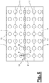
- the distribution can, for example, be according to Figure 4 and 5 be uniform, with several axial rows of holes extending over the entire body length being evenly distributed over the body or cylinder circumference. In another design, the rows of holes can extend only over a portion of the body length or, if necessary, be interrupted.
- perforations may be arranged in a different pattern and distribution, possibly only locally on the body shell and surrounded by solid shell areas. Such local clusters of perforations may be arranged multiple times across the body shell with a uniaxial or multiaxial offset, e.g., with offset in the axial and circumferential directions of the rollers (7, 8).
- the perforation design may also be modified as needed.
- the respective design of the perforation arrangement can serve both deformation and strengthening purposes, as well as decorative purposes.
- the embossing body (7) and the counterbody (8) can have a common or synchronized drive mechanism (13) for their movement, in particular rotation.
- the drive mechanism (13) and the contact or clamping contact drive and advance the web (2) on the one hand.
- the aforementioned aligned arrangement of the perforations (10, 12) at the passage point of the fluid flow (6) is ensured.
- the drive system (13) can comprise one or more drives, in particular rotary drives.
- a suitable control system (not shown) can be provided to control the drive system (13) or its drive(s).
- the other components of the embossing device (4), in particular the overpressure and/or vacuum source (14, 15), can also be connected to this control system.
- the nozzle (17) locally directs a defined fluid flow (6) against the perforated body shell (11) of the preferably rotating counter-body (8). Discrete flow strands emerge from the openings of the perforation (12), each directed against an opening in the perforation (10). Ambient air can also be drawn in by means of a vacuum in the embossing body (7) or its body shell (9). become.
- the negative pressure in the embossing body (7) creates a bead-like deformation in its perforation (10), which can be further perforated with a sharp fluid flow (6) from the nozzle (17).
- a perforation (12) of the counter body (8) with relatively small openings the bead-like deformation is smaller or flatter than with a larger perforation (12) according to Figure 5 .
- Ambient air can be drawn in through the gap at the contact point (32) and/or from a hollow counter-body (8) through its perforation (12).
- the drawing in of ambient air outside the contact area (32) of the bodies or rollers (7, 8) can be prevented, e.g., by appropriately covering the perforation(s) (10, 12) of the embossing body (7) and/or the counter-body (8).
- the same effect can be achieved by a diaphragm (35) arranged in the hollow counter-body (8), which has only a local diaphragm opening at the said contact point (32) of the bodies (7, 8) or the passage point of the fluid flow (6).
- the overpressure source (15) can build up an overpressure in the entire hollow interior of the counter-body (7) or of a possibly multi-layered and hollow body shell (11).
- the counter body (7) can be omitted, leaving only the nozzle (17). Furthermore, it is possible to provide only one overpressure source (15) or one vacuum source (14). In the latter case, the vacuum in the embossing body (7) or its body shell (9) can primarily draw in ambient air.
- the openings of the perforation (12') of the counter roller following in the direction of web travel (8') are smaller than the holes of the perforation (10) of the embossing roller (7). They can be used in the embodiment of Figure 4 correspond.
- the small openings of the perforation (12) are arranged at the contact point (32) in an overlapping, preferably centrally aligned, manner opposite the openings of the perforation (10).
- the small openings and/or a nozzle (17) (not shown) each emit a sharp fluid jet that penetrates and perforates the respective associated and already existing deformation of the web (2).
- the embossing device (4) comprises a single embossing tool (5).
- a multiple arrangement of embossing tools (5) may be present.
- the embossing body (7) in particular the embossing roller, is partially covered or wrapped by the web (2). Alternatively, a tangential alignment is possible.
- the embossing body (7) and, if applicable, the counter-body (8) do not have to be part of the web guide (23). They can also have a body shell (9, 11) that is differently shaped in the contact area, in particular a flat one. They can be cyclically advanced to the web (2), in particular a flat section of the web, for embossing and then removed again.
- the web (2) can be moved discontinuously in this and other cases. It is also possible to switch the vacuum source (14) and/or the overpressure source (15) and have them act intermittently.
- embossing device (4) is designed as an independent and separate unit. It can also be spaced further from the heating device (3) in the transport direction (25) of the web (2) than in the illustrated embodiments.
- the conveyor device (22) is adapted accordingly.
- the distance from the heating device (3) can be selected to be just large enough to prevent heat loss in the web (2), which would be detrimental to the embossing process. Thermal insulation can prevent or minimize heat loss from the web (2) and allow for larger distances.
- additional machine parts or components that subject the web (2) to additional treatment can also be arranged between the embossing device (4) and the heating device (3).
- a single web of material (2) passes through the heating device (3) and the embossing device (4).
- a multiple arrangement of webs (2) is possible.
- several webs of material (2) can be transported separately through the heating device (3) and brought together at the embossing device (3) for a common embossing process.
- the material web (2) has a continuous, mat-like structure, with its width being greater than its thickness. It can have a substantially flat and homogeneous surface on one broad side before entering the embossing device (3). Alternatively, the material web (2) can be formed by individual parallel Strands are formed.
- the claimed embossing technique and, if applicable, the heat treatment technique are also suitable, with appropriate adaptation, for webs (2) made of a different material, e.g., a strip or foil made of metal, plastic, or the like.
Landscapes
- Engineering & Computer Science (AREA)
- Mechanical Engineering (AREA)
- Textile Engineering (AREA)
- Treatment Of Fiber Materials (AREA)
- Machines For Manufacturing Corrugated Board In Mechanical Paper-Making Processes (AREA)
Claims (16)
- Dispositif d'estampage pour une bande de produit (2), qui est formée en un matériau fibreux textile,notamment une nappe de fibres non tissées, ou en un ruban ou une feuille de métal, de plastique ou similaire,le dispositif d'estampage (4) comprenant un outil d'estampage (5) pour estamper la bande de produit (2),l'outil d'estampage (5) estampant la bande de produit (2) avec une dépression fluidique et une surpression fluidique et avec un courant de fluide (6), à savoir un courant de gaz,- le courant de gaz (6) présentant une température supérieure à celle de la bande de produit (2) sollicitée,- l'outil d'estampage (5) présentant un corps d'estampage (7) réalisé sous forme de cylindre d'estampage rotatif avec une enveloppe cylindrique perforée (9), contre l'enveloppe cylindrique (9) duquel s'applique la bande de produit (2),- l'enveloppe cylindrique perforée (9) étant réalisée avec une paroi lisse sur le côté extérieur orienté vers la bande de produit (2),- le dispositif d'estampage (4) présentant une source de dépression commandable (14), à savoir un dispositif d'aspiration, qui est relié par écoulement au corps d'estampage creux (7),- une dépression étant appliquée par la source de dépression (14) sur la perforation (10) de l'enveloppe cylindrique (9), laquelle aspire le matériau de la bande de produit appliqué dans la perforation (10) et le déforme ainsi à la manière d'un bourrelet,- le dispositif d'estampage (4) présentant en outre une source de surpression (15) commandable, à savoir un dispositif de soufflage, qui dirige le courant de gaz (6) contre le corps d'estampage (7) et le côté extérieur de la bande de produit (2) qui y est appliquée,- le dispositif de soufflage étant relié par écoulement à une buse (17) ou à un diaphragme (35) dirigé(e) contre le corps d'estampage (7) et la bande de produit (2) qui y est appliquée,- le dispositif d'estampage (4) présentant un dispositif de transport (22) pour le transport de préférence continu de la bande de produit (2).
- Dispositif d'estampage selon la revendication 1, caractérisé en ce que l'outil d'estampage (5) perfore la bande de produit (2) avec le courant de gaz.
- Dispositif d'estampage selon la revendication 1 ou 2, caractérisé en ce que l'outil d'estampage (5) présente également un contre-corps (8) avec une enveloppe de corps (11) perforée, qui est agencé en face du corps d'estampage (7) transversalement à la bande de produit (2).
- Dispositif d'estampage selon la revendication 3, caractérisé en ce que le contre-corps (8) est réalisé sous forme cylindrique de manière correspondante et sous forme de contre-cylindre rotatif.
- Dispositif d'estampage selon l'une quelconque des revendications précédentes, caractérisé en ce que le dispositif de soufflage est relié au contre-corps (8) de préférence creux par écoulement et la buse (17) ou le diaphragme (35) étant agencé dans le contre-corps (8) de préférence de manière stationnaire.
- Dispositif d'estampage selon la revendication 5, caractérisé en ce que la buse (17) ou le diaphragme (35) dans le contre-corps (8) est dirigé(e) du côté de la sortie contre l'enveloppe de corps perforée (11) et émet le courant de fluide (6) à travers la perforation (12) du contre-corps (8), la buse (17) dans le contre-corps (8) étant dirigée du côté de la sortie contre le point de contact (32) du corps d'estampage (7), du contre-corps (8) et de la bande de produit (2).
- Dispositif d'estampage selon l'une quelconque des revendications 5 ou 6, caractérisé en ce que la buse (17) ou le diaphragme (35) émet un mince courant de fluide chaud (6) qui perfore une zone déformée de la bande de produit (2).
- Dispositif d'estampage selon l'une quelconque des revendications 3 à 7, caractérisé en ce que les perforations (10, 12) du corps d'estampage (7) et du contre-corps (8) sont adaptées l'une à l'autre et agencées en alignement pour le passage d'un courant de fluide (6), notamment d'un courant de gaz, la perforation (10) du corps d'estampage (7) et éventuellement la perforation (12) du contre-corps (8) étant agencées et réalisées pour réaliser un motif d'estampage souhaité.
- Dispositif d'estampage selon l'une quelconque des revendications 3 à 8, caractérisé en ce qu'au corps d'estampage (7) sont associés plusieurs contre-corps (8) qui sont réalisés sous forme identique ou différente, présentant par exemple une perforation (12) différente, notamment des tailles de trous différentes.
- Dispositif de traitement thermique pour une bande de produit (2), qui est formée en un matériau fibreux textile,notamment une nappe de fibres non tissées, ou en un ruban ou une feuille de métal, de plastique ou similaire,le dispositif de traitement thermique (1) comprenant un dispositif de chauffage (3) et un dispositif d'estampage (4) pour la bande de produit (2), caractérisé en ce que le dispositif d'estampage (4) est réalisé selon au moins l'une quelconque des revendications 1 à 9, le dispositif d'estampage (4) étant agencé à l'intérieur du dispositif de chauffage (3) ou derrière le dispositif de chauffage (3) dans la direction de transport (25) de la bande de produit (2) en mouvement.
- Installation de traitement de fibres pour une bande de produit (2), qui est formée en un matériau fibreux textile,notamment une nappe de fibres non tissée, ou en un ruban ou une feuille en métal, en plastique ou similaire,l'installation de traitement de fibres (29) comprenant un générateur de poils, notamment une carde ou une nappeuse, un dispositif de formation de nappe et un dispositif de traitement thermique (1) pour la bande de produit (2), caractérisée en ce que le dispositif de traitement thermique (1) est réalisé selon la revendication 10.
- Procédé d'estampage d'une bande de produit (2), qui est formée en matériau fibreux textile,notamment une nappe de fibres non tissées, ou en un ruban ou une feuille de métal, de plastique ou similaire,avec un outil d'estampage (5), la bande de produit (2) étant estampée par l'outil d'estampage (5) avec une dépression fluidique et une surpression fluidique et avec un courant de fluide (6), à savoir un courant de gaz,- le courant de gaz (6) présentant une température supérieure à celle de la bande de produit (2) sollicitée,- l'outil d'estampage (5) étant réalisé selon la revendication 1.
- Procédé selon la revendication 12, caractérisé en ce que la bande de produit (2) est estampée et éventuellement perforée avec un courant de gaz, la bande de produit (2) étant agencée à un point de contact (32) entre un corps d'estampage (7) avec une enveloppe de corps (9) perforée et un contre-corps (8) avec une enveloppe de corps (11) perforée.
- Procédé selon la revendication 12 ou 13, caractérisé en ce qu'une déformation locale de la bande de produit (2), produite par dépression sur le corps d'estampage (7) et se trouvant dans la perforation (10) locale, est perforée par un courant de fluide tranchant, notamment sous forme de jet, et très chaud.
- Procédé selon la revendication 12, 13 ou 14, caractérisé en ce que plusieurs bandes de produit (2) sont transportées séparément les unes des autres à travers le dispositif de chauffage (3) et sont réunies au niveau du dispositif d'estampage (3) pour un processus d'estampage commun.
- Procédé selon la revendication 12, 13, 14 ou 15, caractérisé en ce que le procédé d'estampage est réalisé à l'intérieur ou à l'extérieur et en aval d'un dispositif de chauffage (3), notamment d'un four, pour la consolidation thermique de la bande de produit.
Applications Claiming Priority (3)
| Application Number | Priority Date | Filing Date | Title |
|---|---|---|---|
| DE202015104671.5U DE202015104671U1 (de) | 2015-09-03 | 2015-09-03 | Prägeeinrichtung |
| EP16766871.4A EP3344810B8 (fr) | 2015-09-03 | 2016-09-03 | Dispositif de gaufrage |
| PCT/EP2016/070788 WO2017037273A1 (fr) | 2015-09-03 | 2016-09-03 | Dispositif de gaufrage |
Related Parent Applications (2)
| Application Number | Title | Priority Date | Filing Date |
|---|---|---|---|
| EP16766871.4A Division EP3344810B8 (fr) | 2015-09-03 | 2016-09-03 | Dispositif de gaufrage |
| EP16766871.4A Division-Into EP3344810B8 (fr) | 2015-09-03 | 2016-09-03 | Dispositif de gaufrage |
Publications (3)
| Publication Number | Publication Date |
|---|---|
| EP4001486A1 EP4001486A1 (fr) | 2022-05-25 |
| EP4001486B1 true EP4001486B1 (fr) | 2025-04-09 |
| EP4001486C0 EP4001486C0 (fr) | 2025-04-09 |
Family
ID=56943477
Family Applications (2)
| Application Number | Title | Priority Date | Filing Date |
|---|---|---|---|
| EP16766871.4A Not-in-force EP3344810B8 (fr) | 2015-09-03 | 2016-09-03 | Dispositif de gaufrage |
| EP21212756.7A Active EP4001486B1 (fr) | 2015-09-03 | 2016-09-03 | Dispositif d'estampage et procédé d'estampage |
Family Applications Before (1)
| Application Number | Title | Priority Date | Filing Date |
|---|---|---|---|
| EP16766871.4A Not-in-force EP3344810B8 (fr) | 2015-09-03 | 2016-09-03 | Dispositif de gaufrage |
Country Status (3)
| Country | Link |
|---|---|
| EP (2) | EP3344810B8 (fr) |
| DE (1) | DE202015104671U1 (fr) |
| WO (1) | WO2017037273A1 (fr) |
Families Citing this family (4)
| Publication number | Priority date | Publication date | Assignee | Title |
|---|---|---|---|---|
| CN115997059B (zh) | 2020-07-03 | 2026-03-24 | 易希提卫生与保健公司 | 棉纸产品、棉纸产品卷筒和堆叠以及制造方法 |
| US20230287630A1 (en) | 2020-07-03 | 2023-09-14 | Essity Hygiene And Health Aktiebolag | Coreless Rolls of a Tissue Paper Product and Methods of Manufacturing Coreless Rolls |
| WO2023126639A1 (fr) | 2021-12-29 | 2023-07-06 | Essity Hygiene And Health Aktiebolag | Rouleaux sans mandrin d'un produit de papier ouaté et procédés de fabrication de rouleaux sans mandrin |
| DE202023100465U1 (de) | 2023-01-31 | 2024-05-06 | Autefa Solutions Germany Gmbh | Prägeeinrichtung |
Family Cites Families (13)
| Publication number | Priority date | Publication date | Assignee | Title |
|---|---|---|---|---|
| DE68915748T2 (de) | 1989-03-09 | 1994-09-22 | Perfojet Sa | Vorrichtung zum Perforieren eines blattartigen Produktes. |
| JP3171457B2 (ja) | 1991-04-26 | 2001-05-28 | 日本フイルコン株式会社 | 突起を設けた不織布製造用ベルト及び模様を形成した不織布の製造方法 |
| RU2105092C1 (ru) | 1992-02-18 | 1998-02-20 | МакНЕЙЛ-ППС, ИНК. | Нетканый материал (варианты), устройство для изготовления нетканого материала, устройство для изготовления перераспределенного нетканого материала, способ изготовления нетканого материала |
| DE19912279A1 (de) | 1999-03-18 | 2000-09-21 | Fleissner Maschf Gmbh Co | Verfahren und Vorrichtung zur Herstellung von Nonwovens mit Präge- oder Lochmuster mittels hydrodynamischer Vernadelung |
| US6572722B1 (en) * | 1999-11-22 | 2003-06-03 | The Procter & Gamble Company | Process for autogeneously bonding laminae of a mult-lamina cellulosic substrate |
| DE10132563A1 (de) | 2001-07-10 | 2003-01-30 | Fleissner Maschf Gmbh Co | Verfahren zur farblosen Musterung einer Warenbahn und Vorrichtung zur Durchführung des Verfahrens |
| EP1434904A4 (fr) * | 2001-09-07 | 2005-04-13 | Polymer Group Inc | Tissu non tisse a images comprenant des fibres lyocell |
| FI121182B (fi) * | 2004-06-18 | 2010-08-13 | Suominen Nonwovens Ltd | Menetelmä kuitukankaan valmistamiseksi |
| US20070256286A1 (en) | 2006-05-05 | 2007-11-08 | Pgi Polymer, Inc. | Method and apparatus for perforating a fibrous web |
| DE102007043543A1 (de) | 2007-09-12 | 2009-03-19 | Fleissner Gmbh | Verfahren und Vorrichtung zur Herstellung dreidimensional strukturierter Vliesstoffe |
| DE102007053030A1 (de) | 2007-11-05 | 2009-05-07 | Fleissner Gmbh | Einrichtung zur Beaufschlagung von Stoffen mittels heißen Gasen |
| DE102007053991A1 (de) | 2007-11-13 | 2009-05-14 | Fleissner Gmbh | Vorrichtung zur Beaufschlagung von Stoffen mittels heißen Gasen |
| DE202011004335U1 (de) | 2011-03-23 | 2012-03-26 | Trützschler Nonwovens Gmbh | Einrichtung zur Verfestigung eines textilen Produktes mittels heißen Gasen |
-
2015
- 2015-09-03 DE DE202015104671.5U patent/DE202015104671U1/de not_active Expired - Lifetime
-
2016
- 2016-09-03 EP EP16766871.4A patent/EP3344810B8/fr not_active Not-in-force
- 2016-09-03 WO PCT/EP2016/070788 patent/WO2017037273A1/fr not_active Ceased
- 2016-09-03 EP EP21212756.7A patent/EP4001486B1/fr active Active
Also Published As
| Publication number | Publication date |
|---|---|
| EP4001486A1 (fr) | 2022-05-25 |
| EP3344810B1 (fr) | 2021-12-08 |
| DE202015104671U1 (de) | 2016-12-06 |
| EP3344810B8 (fr) | 2022-02-09 |
| EP3344810A1 (fr) | 2018-07-11 |
| WO2017037273A1 (fr) | 2017-03-09 |
| EP4001486C0 (fr) | 2025-04-09 |
Similar Documents
| Publication | Publication Date | Title |
|---|---|---|
| EP3344810B1 (fr) | Dispositif de gaufrage | |
| EP3011092B1 (fr) | Procédé et système de production de non-tissé à fibres de carbone enchevêtrées et procédé de production de non tissé à éléments tridimensionnels | |
| EP2337670B1 (fr) | Procédé et dispositif de fabrication d'éléments en matériau composite ainsi qu'unité de pression | |
| EP2140052B1 (fr) | Dispositif d'ecartement servant a ecarter des faisceaux de filaments de fibres, et dispositif correspondant de fabrication de préformes | |
| DE102011018320B4 (de) | Verfahren und Vorrichtung zur Dickenprofilregelung | |
| DE3528365C2 (fr) | ||
| DE1785302C3 (de) | Verfahren und Vorrichtung zum kontinuierlichen Herstellen eines Wirrfadenvlieses und Wirrfadenvlies | |
| EP2136979A1 (fr) | Tampon elastique d'application de fibres, dispositif d'application comprenant un tel tampon et utilisation de ce dispositif | |
| DE102007012608A1 (de) | Verfahren und Vorrichtung zum Herstellen einer Preform für eine kraftflussgerechte Faserverbundstruktur | |
| EP1825046B1 (fr) | Formation de motifs sur produit sms | |
| EP3526042B1 (fr) | Dispositif pour contre-coller un matériau de revêtement thermoplastique sur un substrat | |
| DE4312309A1 (de) | Verfahren und Vorrichtungen zur Herstellung eines Spinnvlies-Flächenproduktes | |
| EP2689060A1 (fr) | Dispositif de consolidation d'un produit textile au moyen de gaz chauds | |
| EP3516098A1 (fr) | Dispositif de formation de non-tissé aérodynamique et procédé associé | |
| EP2020457A2 (fr) | Procédé et installation destinés au traitement continu de bandes de marchandise textiles | |
| DE602005002542T2 (de) | Übertragung von harz zum formen von befestigungselementen | |
| DE3708122A1 (de) | Verfahren und vorrichtung zur herstellung von mehrschichtplatten | |
| DE202014102656U1 (de) | Prägeeinrichtung | |
| DE102006016584B4 (de) | Verfahren und Vorrichtung zum Auftragen von Klebstofffäden und -punkten auf ein Substrat | |
| DE10132196A1 (de) | Perforiertes Laminat | |
| DE2035449A1 (en) | Low density plastic composite - for use as packing light weight construction, or insulating material | |
| DE202023100465U1 (de) | Prägeeinrichtung | |
| DE4333877A1 (de) | Verfahren und Vorrichtung zum Trennen von Geweben schmelzfähigen Materials | |
| DE2058585A1 (de) | Verfahren und Vorrichtung zur Herstellung von textilen Strukturen | |
| DE69610212T2 (de) | Luft-Überlappungseinrichtung für fasriges Material mit linearer Zu/Abnahme |
Legal Events
| Date | Code | Title | Description |
|---|---|---|---|
| PUAI | Public reference made under article 153(3) epc to a published international application that has entered the european phase |
Free format text: ORIGINAL CODE: 0009012 |
|
| STAA | Information on the status of an ep patent application or granted ep patent |
Free format text: STATUS: THE APPLICATION HAS BEEN PUBLISHED |
|
| AC | Divisional application: reference to earlier application |
Ref document number: 3344810 Country of ref document: EP Kind code of ref document: P |
|
| AK | Designated contracting states |
Kind code of ref document: A1 Designated state(s): AL AT BE BG CH CY CZ DE DK EE ES FI FR GB GR HR HU IE IS IT LI LT LU LV MC MK MT NL NO PL PT RO RS SE SI SK SM TR |
|
| STAA | Information on the status of an ep patent application or granted ep patent |
Free format text: STATUS: REQUEST FOR EXAMINATION WAS MADE |
|
| 17P | Request for examination filed |
Effective date: 20221122 |
|
| RBV | Designated contracting states (corrected) |
Designated state(s): AL AT BE BG CH CY CZ DE DK EE ES FI FR GB GR HR HU IE IS IT LI LT LU LV MC MK MT NL NO PL PT RO RS SE SI SK SM TR |
|
| GRAP | Despatch of communication of intention to grant a patent |
Free format text: ORIGINAL CODE: EPIDOSNIGR1 |
|
| STAA | Information on the status of an ep patent application or granted ep patent |
Free format text: STATUS: GRANT OF PATENT IS INTENDED |
|
| RIC1 | Information provided on ipc code assigned before grant |
Ipc: B31F 1/00 20060101ALI20241011BHEP Ipc: D04H 1/495 20120101AFI20241011BHEP |
|
| INTG | Intention to grant announced |
Effective date: 20241029 |
|
| GRAS | Grant fee paid |
Free format text: ORIGINAL CODE: EPIDOSNIGR3 |
|
| GRAA | (expected) grant |
Free format text: ORIGINAL CODE: 0009210 |
|
| STAA | Information on the status of an ep patent application or granted ep patent |
Free format text: STATUS: THE PATENT HAS BEEN GRANTED |
|
| AC | Divisional application: reference to earlier application |
Ref document number: 3344810 Country of ref document: EP Kind code of ref document: P |
|
| AK | Designated contracting states |
Kind code of ref document: B1 Designated state(s): AL AT BE BG CH CY CZ DE DK EE ES FI FR GB GR HR HU IE IS IT LI LT LU LV MC MK MT NL NO PL PT RO RS SE SI SK SM TR |
|
| REG | Reference to a national code |
Ref country code: GB Ref legal event code: FG4D Free format text: NOT ENGLISH |
|
| REG | Reference to a national code |
Ref country code: CH Ref legal event code: EP |
|
| REG | Reference to a national code |
Ref country code: DE Ref legal event code: R096 Ref document number: 502016016950 Country of ref document: DE |
|
| REG | Reference to a national code |
Ref country code: IE Ref legal event code: FG4D Free format text: LANGUAGE OF EP DOCUMENT: GERMAN |
|
| U01 | Request for unitary effect filed |
Effective date: 20250508 |
|
| U07 | Unitary effect registered |
Designated state(s): AT BE BG DE DK EE FI FR IT LT LU LV MT NL PT RO SE SI Effective date: 20250515 |
|
| PG25 | Lapsed in a contracting state [announced via postgrant information from national office to epo] |
Ref country code: ES Free format text: LAPSE BECAUSE OF FAILURE TO SUBMIT A TRANSLATION OF THE DESCRIPTION OR TO PAY THE FEE WITHIN THE PRESCRIBED TIME-LIMIT Effective date: 20250409 |
|
| PG25 | Lapsed in a contracting state [announced via postgrant information from national office to epo] |
Ref country code: GR Free format text: LAPSE BECAUSE OF FAILURE TO SUBMIT A TRANSLATION OF THE DESCRIPTION OR TO PAY THE FEE WITHIN THE PRESCRIBED TIME-LIMIT Effective date: 20250710 Ref country code: NO Free format text: LAPSE BECAUSE OF FAILURE TO SUBMIT A TRANSLATION OF THE DESCRIPTION OR TO PAY THE FEE WITHIN THE PRESCRIBED TIME-LIMIT Effective date: 20250709 |
|
| PG25 | Lapsed in a contracting state [announced via postgrant information from national office to epo] |
Ref country code: PL Free format text: LAPSE BECAUSE OF FAILURE TO SUBMIT A TRANSLATION OF THE DESCRIPTION OR TO PAY THE FEE WITHIN THE PRESCRIBED TIME-LIMIT Effective date: 20250409 |
|
| PG25 | Lapsed in a contracting state [announced via postgrant information from national office to epo] |
Ref country code: HR Free format text: LAPSE BECAUSE OF FAILURE TO SUBMIT A TRANSLATION OF THE DESCRIPTION OR TO PAY THE FEE WITHIN THE PRESCRIBED TIME-LIMIT Effective date: 20250409 |
|
| PG25 | Lapsed in a contracting state [announced via postgrant information from national office to epo] |
Ref country code: RS Free format text: LAPSE BECAUSE OF FAILURE TO SUBMIT A TRANSLATION OF THE DESCRIPTION OR TO PAY THE FEE WITHIN THE PRESCRIBED TIME-LIMIT Effective date: 20250709 |
|
| PG25 | Lapsed in a contracting state [announced via postgrant information from national office to epo] |
Ref country code: IS Free format text: LAPSE BECAUSE OF FAILURE TO SUBMIT A TRANSLATION OF THE DESCRIPTION OR TO PAY THE FEE WITHIN THE PRESCRIBED TIME-LIMIT Effective date: 20250809 |
|
| U20 | Renewal fee for the european patent with unitary effect paid |
Year of fee payment: 10 Effective date: 20250923 |
|
| PG25 | Lapsed in a contracting state [announced via postgrant information from national office to epo] |
Ref country code: SM Free format text: LAPSE BECAUSE OF FAILURE TO SUBMIT A TRANSLATION OF THE DESCRIPTION OR TO PAY THE FEE WITHIN THE PRESCRIBED TIME-LIMIT Effective date: 20250409 |
|
| PG25 | Lapsed in a contracting state [announced via postgrant information from national office to epo] |
Ref country code: CZ Free format text: LAPSE BECAUSE OF FAILURE TO SUBMIT A TRANSLATION OF THE DESCRIPTION OR TO PAY THE FEE WITHIN THE PRESCRIBED TIME-LIMIT Effective date: 20250409 |
|
| PG25 | Lapsed in a contracting state [announced via postgrant information from national office to epo] |
Ref country code: SK Free format text: LAPSE BECAUSE OF FAILURE TO SUBMIT A TRANSLATION OF THE DESCRIPTION OR TO PAY THE FEE WITHIN THE PRESCRIBED TIME-LIMIT Effective date: 20250409 |
|
| PLBE | No opposition filed within time limit |
Free format text: ORIGINAL CODE: 0009261 |
|
| STAA | Information on the status of an ep patent application or granted ep patent |
Free format text: STATUS: NO OPPOSITION FILED WITHIN TIME LIMIT |
|
| REG | Reference to a national code |
Ref country code: CH Ref legal event code: L10 Free format text: ST27 STATUS EVENT CODE: U-0-0-L10-L00 (AS PROVIDED BY THE NATIONAL OFFICE) Effective date: 20260218 |
|
| 26N | No opposition filed |
Effective date: 20260112 |
|
| REG | Reference to a national code |
Ref country code: CH Ref legal event code: H13 Free format text: ST27 STATUS EVENT CODE: U-0-0-H10-H13 (AS PROVIDED BY THE NATIONAL OFFICE) Effective date: 20260504 |
|
| GBPC | Gb: european patent ceased through non-payment of renewal fee |
Effective date: 20250903 |
|
| PG25 | Lapsed in a contracting state [announced via postgrant information from national office to epo] |
Ref country code: MC Free format text: LAPSE BECAUSE OF FAILURE TO SUBMIT A TRANSLATION OF THE DESCRIPTION OR TO PAY THE FEE WITHIN THE PRESCRIBED TIME-LIMIT Effective date: 20250409 |
|
| PG25 | Lapsed in a contracting state [announced via postgrant information from national office to epo] |
Ref country code: GB Free format text: LAPSE BECAUSE OF NON-PAYMENT OF DUE FEES Effective date: 20250903 |
|
| PG25 | Lapsed in a contracting state [announced via postgrant information from national office to epo] |
Ref country code: CH Free format text: LAPSE BECAUSE OF NON-PAYMENT OF DUE FEES Effective date: 20250930 Ref country code: IE Free format text: LAPSE BECAUSE OF NON-PAYMENT OF DUE FEES Effective date: 20250903 |