EP4001534B1 - Fixation de parement et méthode procurant une structure en béton munie d'une fixation de parement - Google Patents
Fixation de parement et méthode procurant une structure en béton munie d'une fixation de parement Download PDFInfo
- Publication number
- EP4001534B1 EP4001534B1 EP21208118.6A EP21208118A EP4001534B1 EP 4001534 B1 EP4001534 B1 EP 4001534B1 EP 21208118 A EP21208118 A EP 21208118A EP 4001534 B1 EP4001534 B1 EP 4001534B1
- Authority
- EP
- European Patent Office
- Prior art keywords
- spike
- sleeve
- spacer
- attaching
- cladding
- Prior art date
- Legal status (The legal status is an assumption and is not a legal conclusion. Google has not performed a legal analysis and makes no representation as to the accuracy of the status listed.)
- Active
Links
Images


Classifications
-
- E—FIXED CONSTRUCTIONS
- E04—BUILDING
- E04B—GENERAL BUILDING CONSTRUCTIONS; WALLS, e.g. PARTITIONS; ROOFS; FLOORS; CEILINGS; INSULATION OR OTHER PROTECTION OF BUILDINGS
- E04B1/00—Constructions in general; Structures which are not restricted either to walls, e.g. partitions, or floors or ceilings or roofs
- E04B1/38—Connections for building structures in general
- E04B1/41—Connecting devices specially adapted for embedding in concrete or masonry
- E04B1/4178—Masonry wall ties
-
- E—FIXED CONSTRUCTIONS
- E04—BUILDING
- E04C—STRUCTURAL ELEMENTS; BUILDING MATERIALS
- E04C2/00—Building elements of relatively thin form for the construction of parts of buildings, e.g. sheet materials, slabs, or panels
- E04C2/02—Building elements of relatively thin form for the construction of parts of buildings, e.g. sheet materials, slabs, or panels characterised by specified materials
- E04C2/04—Building elements of relatively thin form for the construction of parts of buildings, e.g. sheet materials, slabs, or panels characterised by specified materials of concrete or other stone-like material; of asbestos cement; of cement and other mineral fibres
- E04C2/044—Building elements of relatively thin form for the construction of parts of buildings, e.g. sheet materials, slabs, or panels characterised by specified materials of concrete or other stone-like material; of asbestos cement; of cement and other mineral fibres of concrete
-
- B—PERFORMING OPERATIONS; TRANSPORTING
- B28—WORKING CEMENT, CLAY, OR STONE
- B28B—SHAPING CLAY OR OTHER CERAMIC COMPOSITIONS; SHAPING SLAG; SHAPING MIXTURES CONTAINING CEMENTITIOUS MATERIAL, e.g. PLASTER
- B28B5/00—Producing shaped articles from the material in moulds or on moulding surfaces, carried or formed by, in or on conveyors irrespective of the manner of shaping
- B28B5/04—Producing shaped articles from the material in moulds or on moulding surfaces, carried or formed by, in or on conveyors irrespective of the manner of shaping in moulds moved in succession past one or more shaping stations
-
- B—PERFORMING OPERATIONS; TRANSPORTING
- B28—WORKING CEMENT, CLAY, OR STONE
- B28B—SHAPING CLAY OR OTHER CERAMIC COMPOSITIONS; SHAPING SLAG; SHAPING MIXTURES CONTAINING CEMENTITIOUS MATERIAL, e.g. PLASTER
- B28B7/00—Moulds; Cores; Mandrels
- B28B7/0002—Auxiliary parts or elements of the mould
- B28B7/0014—Fastening means for mould parts, e.g. for attaching mould walls on mould tables; Mould clamps
-
- B—PERFORMING OPERATIONS; TRANSPORTING
- B28—WORKING CEMENT, CLAY, OR STONE
- B28B—SHAPING CLAY OR OTHER CERAMIC COMPOSITIONS; SHAPING SLAG; SHAPING MIXTURES CONTAINING CEMENTITIOUS MATERIAL, e.g. PLASTER
- B28B7/00—Moulds; Cores; Mandrels
- B28B7/0029—Moulds or moulding surfaces not covered by B28B7/0058 - B28B7/36 and B28B7/40 - B28B7/465, e.g. moulds assembled from several parts
- B28B7/0032—Moulding tables or similar mainly horizontal moulding surfaces
-
- E—FIXED CONSTRUCTIONS
- E04—BUILDING
- E04B—GENERAL BUILDING CONSTRUCTIONS; WALLS, e.g. PARTITIONS; ROOFS; FLOORS; CEILINGS; INSULATION OR OTHER PROTECTION OF BUILDINGS
- E04B1/00—Constructions in general; Structures which are not restricted either to walls, e.g. partitions, or floors or ceilings or roofs
- E04B1/02—Structures consisting primarily of load-supporting, block-shaped, or slab-shaped elements
- E04B1/04—Structures consisting primarily of load-supporting, block-shaped, or slab-shaped elements the elements consisting of concrete, e.g. reinforced concrete, or other stone-like material
- E04B1/043—Connections specially adapted therefor
-
- E—FIXED CONSTRUCTIONS
- E04—BUILDING
- E04B—GENERAL BUILDING CONSTRUCTIONS; WALLS, e.g. PARTITIONS; ROOFS; FLOORS; CEILINGS; INSULATION OR OTHER PROTECTION OF BUILDINGS
- E04B1/00—Constructions in general; Structures which are not restricted either to walls, e.g. partitions, or floors or ceilings or roofs
- E04B1/38—Connections for building structures in general
- E04B1/41—Connecting devices specially adapted for embedding in concrete or masonry
-
- E—FIXED CONSTRUCTIONS
- E04—BUILDING
- E04B—GENERAL BUILDING CONSTRUCTIONS; WALLS, e.g. PARTITIONS; ROOFS; FLOORS; CEILINGS; INSULATION OR OTHER PROTECTION OF BUILDINGS
- E04B1/00—Constructions in general; Structures which are not restricted either to walls, e.g. partitions, or floors or ceilings or roofs
- E04B1/62—Insulation or other protection; Elements or use of specified material therefor
- E04B1/74—Heat, sound or noise insulation, absorption, or reflection; Other building methods affording favourable thermal or acoustical conditions, e.g. accumulating of heat within walls
- E04B1/76—Heat, sound or noise insulation, absorption, or reflection; Other building methods affording favourable thermal or acoustical conditions, e.g. accumulating of heat within walls specifically with respect to heat only
- E04B1/7608—Heat, sound or noise insulation, absorption, or reflection; Other building methods affording favourable thermal or acoustical conditions, e.g. accumulating of heat within walls specifically with respect to heat only comprising a prefabricated insulating layer, disposed between two other layers or panels
- E04B1/7612—Heat, sound or noise insulation, absorption, or reflection; Other building methods affording favourable thermal or acoustical conditions, e.g. accumulating of heat within walls specifically with respect to heat only comprising a prefabricated insulating layer, disposed between two other layers or panels in combination with an air space
- E04B1/7616—Heat, sound or noise insulation, absorption, or reflection; Other building methods affording favourable thermal or acoustical conditions, e.g. accumulating of heat within walls specifically with respect to heat only comprising a prefabricated insulating layer, disposed between two other layers or panels in combination with an air space with insulation-layer locating devices combined with wall ties
-
- E—FIXED CONSTRUCTIONS
- E04—BUILDING
- E04B—GENERAL BUILDING CONSTRUCTIONS; WALLS, e.g. PARTITIONS; ROOFS; FLOORS; CEILINGS; INSULATION OR OTHER PROTECTION OF BUILDINGS
- E04B1/00—Constructions in general; Structures which are not restricted either to walls, e.g. partitions, or floors or ceilings or roofs
- E04B1/62—Insulation or other protection; Elements or use of specified material therefor
- E04B1/74—Heat, sound or noise insulation, absorption, or reflection; Other building methods affording favourable thermal or acoustical conditions, e.g. accumulating of heat within walls
- E04B1/76—Heat, sound or noise insulation, absorption, or reflection; Other building methods affording favourable thermal or acoustical conditions, e.g. accumulating of heat within walls specifically with respect to heat only
- E04B1/762—Exterior insulation of exterior walls
- E04B1/7629—Details of the mechanical connection of the insulation to the wall
-
- E—FIXED CONSTRUCTIONS
- E04—BUILDING
- E04B—GENERAL BUILDING CONSTRUCTIONS; WALLS, e.g. PARTITIONS; ROOFS; FLOORS; CEILINGS; INSULATION OR OTHER PROTECTION OF BUILDINGS
- E04B2/00—Walls, e.g. partitions, for buildings; Wall construction with regard to insulation; Connections specially adapted to walls
- E04B2/02—Walls, e.g. partitions, for buildings; Wall construction with regard to insulation; Connections specially adapted to walls built-up from layers of building elements
- E04B2/42—Walls having cavities between, as well as in, the elements; Walls of elements each consisting of two or more parts, kept in distance by means of spacers, at least one of the parts having cavities
- E04B2/44—Walls having cavities between, as well as in, the elements; Walls of elements each consisting of two or more parts, kept in distance by means of spacers, at least one of the parts having cavities using elements having specially-designed means for stabilising the position; Spacers for cavity walls
-
- E—FIXED CONSTRUCTIONS
- E04—BUILDING
- E04B—GENERAL BUILDING CONSTRUCTIONS; WALLS, e.g. PARTITIONS; ROOFS; FLOORS; CEILINGS; INSULATION OR OTHER PROTECTION OF BUILDINGS
- E04B2/00—Walls, e.g. partitions, for buildings; Wall construction with regard to insulation; Connections specially adapted to walls
- E04B2/56—Load-bearing walls of framework or pillarwork; Walls incorporating load-bearing elongated members
- E04B2/64—Load-bearing walls of framework or pillarwork; Walls incorporating load-bearing elongated members with elongated members of concrete
-
- E—FIXED CONSTRUCTIONS
- E04—BUILDING
- E04C—STRUCTURAL ELEMENTS; BUILDING MATERIALS
- E04C2/00—Building elements of relatively thin form for the construction of parts of buildings, e.g. sheet materials, slabs, or panels
- E04C2/02—Building elements of relatively thin form for the construction of parts of buildings, e.g. sheet materials, slabs, or panels characterised by specified materials
- E04C2/04—Building elements of relatively thin form for the construction of parts of buildings, e.g. sheet materials, slabs, or panels characterised by specified materials of concrete or other stone-like material; of asbestos cement; of cement and other mineral fibres
- E04C2/041—Building elements of relatively thin form for the construction of parts of buildings, e.g. sheet materials, slabs, or panels characterised by specified materials of concrete or other stone-like material; of asbestos cement; of cement and other mineral fibres composed of a number of smaller elements, e.g. bricks, also combined with a slab of hardenable material
-
- E—FIXED CONSTRUCTIONS
- E04—BUILDING
- E04C—STRUCTURAL ELEMENTS; BUILDING MATERIALS
- E04C2/00—Building elements of relatively thin form for the construction of parts of buildings, e.g. sheet materials, slabs, or panels
- E04C2/02—Building elements of relatively thin form for the construction of parts of buildings, e.g. sheet materials, slabs, or panels characterised by specified materials
- E04C2/04—Building elements of relatively thin form for the construction of parts of buildings, e.g. sheet materials, slabs, or panels characterised by specified materials of concrete or other stone-like material; of asbestos cement; of cement and other mineral fibres
- E04C2/06—Building elements of relatively thin form for the construction of parts of buildings, e.g. sheet materials, slabs, or panels characterised by specified materials of concrete or other stone-like material; of asbestos cement; of cement and other mineral fibres reinforced
-
- E—FIXED CONSTRUCTIONS
- E04—BUILDING
- E04C—STRUCTURAL ELEMENTS; BUILDING MATERIALS
- E04C2/00—Building elements of relatively thin form for the construction of parts of buildings, e.g. sheet materials, slabs, or panels
- E04C2/30—Building elements of relatively thin form for the construction of parts of buildings, e.g. sheet materials, slabs, or panels characterised by the shape or structure
- E04C2/38—Building elements of relatively thin form for the construction of parts of buildings, e.g. sheet materials, slabs, or panels characterised by the shape or structure with attached ribs, flanges, or the like, e.g. framed panels
-
- E—FIXED CONSTRUCTIONS
- E04—BUILDING
- E04C—STRUCTURAL ELEMENTS; BUILDING MATERIALS
- E04C2/00—Building elements of relatively thin form for the construction of parts of buildings, e.g. sheet materials, slabs, or panels
- E04C2/44—Building elements of relatively thin form for the construction of parts of buildings, e.g. sheet materials, slabs, or panels characterised by the purpose
- E04C2/46—Building elements of relatively thin form for the construction of parts of buildings, e.g. sheet materials, slabs, or panels characterised by the purpose specially adapted for making walls
-
- E—FIXED CONSTRUCTIONS
- E04—BUILDING
- E04C—STRUCTURAL ELEMENTS; BUILDING MATERIALS
- E04C2/00—Building elements of relatively thin form for the construction of parts of buildings, e.g. sheet materials, slabs, or panels
- E04C2/02—Building elements of relatively thin form for the construction of parts of buildings, e.g. sheet materials, slabs, or panels characterised by specified materials
- E04C2/26—Building elements of relatively thin form for the construction of parts of buildings, e.g. sheet materials, slabs, or panels characterised by specified materials composed of materials covered by two or more of groups E04C2/04, E04C2/08, E04C2/10 or of materials covered by one of these groups with a material not specified in one of the groups
- E04C2/284—Building elements of relatively thin form for the construction of parts of buildings, e.g. sheet materials, slabs, or panels characterised by specified materials composed of materials covered by two or more of groups E04C2/04, E04C2/08, E04C2/10 or of materials covered by one of these groups with a material not specified in one of the groups at least one of the materials being insulating
- E04C2/288—Building elements of relatively thin form for the construction of parts of buildings, e.g. sheet materials, slabs, or panels characterised by specified materials composed of materials covered by two or more of groups E04C2/04, E04C2/08, E04C2/10 or of materials covered by one of these groups with a material not specified in one of the groups at least one of the materials being insulating composed of insulating material and concrete, stone or stone-like material
Definitions
- the present invention relates to building technology.
- the invention especially relates to production and finishing of concrete elements.
- the invention relates to a fastener for fastening cladding of a concrete element and a method for installing the fasteners according to the preamble of claim 1.
- One type comprises a cast frame made of reinforced concrete, insulation installed on the frame and an external cladding.
- the external cladding can be plastering applied on the insulation or an external lining fastened onto the concrete frame of the element, such as laid brick cladding.
- the cladding can suspend its own weight, such as brick cladding, or it can be supported by and fastened to the concrete frame and the insulation, such as plastering applied on the cladding.
- the insulation and cladding must be bound to the concrete frame by means of suitable fasteners.
- the outer shell of a cavity wall for example, is connected to the inner shell by means of brick ties.
- brick ties The purpose of brick ties is to transfer pulling and pushing forces between the shells and also to allow a slight mutual movement of the shells.
- Brick ties are dimensioned to suit each construction application. The type, model and length of brick ties are chosen and the required minimum amount (pcs/m2) is calculated for each structure type. Brick ties are usually used for fastening the heat insulation of the building as well.
- One known brick tie comprises a steel spike fastened to the frame of the concrete element or the interior shell and installed into the concrete element by boring a hole for the steel spike into the concrete frame through the insulation of the element.
- the head of the steel spike is provided with a washer to contact the surface of the insulation, the washer being pressed and locked against the insulation by means of a spring steel locking washer.
- the outer end of the steel spike is provided with a loop for providing grip for the brick tie.
- the brick tie is threaded into the loop so that it extends to the mortar joints.
- the grips can vary according to the cladding solution. The method requires a lot of installation work as the brick ties are manually fastened to the frame of the element on the site.
- the insulation is attached to the frame by means of brick ties only after the brick ties have been installed.
- the insulation is fastened by means of plastic fasteners, whereby two sets of fasteners are required, the brick ties and the fasteners for the insulation.
- the steel spike of the brick tie can also be installed into the element during pouring.
- the loop end of the steel spike needed for connecting the grip extends outside the surface of the insulation layer.
- a fastener with a sleeve and a flange for fastening insulation to a concrete support is known from EP3462044 A1 .
- the invention relates to a cladding fastener having a spike attaching to the concrete of the concrete element that can be arranged to run in the insulation of the concrete element, a sleeve fastening to the spike and means for fastening to the grip of the cladding.
- the spike is fastened to the concrete during pouring.
- the cladding fastener comprises an elongated spike, a sleeve having a body and a flange extending to the side from the body and a spacer, wherein the first end of the spike is provided with a grip for fastening to the concrete frame and the second, opposite, end is provided with connection means for attaching to the sleeve and connection means for attaching to the spacer and wherein the spacer comprises connection means for attaching to the spike and a fastener for grip.
- the spike in the method for providing a concrete element with a cladding fastener the spike is fastened to the body of the sleeve, the spike with its sleeve is pressed through the insulation and the insulation provided with the spike is positioned on the pouring table, subsequent to which a concrete layer is poured on the insulation, whereby the first end of the spike is attached to concrete during curing and the flange of the sleeve is positioned against the surface of the insulation opposite the concrete layer, thus locking the insulation onto the concrete by means of the sleeve and the spike.
- connection means of the spike for attaching to the spacer is a thread and the connection means of the spacer for attaching to the spike is a thread.
- connection means for attaching to the sleeve is a thread for attaching the spacer of the spike.
- the spacer is a hole nut, the first end of which is provided with a female thread for attaching to the spike and the second, opposite, end is provided with a loop forming a hole.
- the spacer is a hole nut, the first end of which is provided with a female thread for attaching to the spike and the second, opposite, end is provided with a flange extending to the side in relation to the axial direction of the female thread.
- the cladding fastener comprises a grip, such as at least one of the following: A U-shaped brick tie, steel spike and at least one piece of perforated band, steel spike and at least one L-shaped grip, having a loop at one leg, or binding mesh.
- the spacer is a hole nut, the first end of which is provided with a female thread for attaching to the spike and the second, opposite, end is provided with a bar extending in the axial direction of the female thread.
- the cladding fastener comprises an elongated spike, a sleeve having a body and a flange extending to the side from the body and a spacer, whereby the first end of the spike is provided with a form lock for fastening to the concrete frame and the second, opposite, end is provided with connection means for attaching to the sleeve and connection means for attaching to the spacer and wherein the spacer comprises spacer connection means for attaching to the spike and a fastener for the support mesh and the flange is provided with a support shoulder having a grip means for the support spike and a support spike.
- the cladding fastener comprises a positioning ring having connection means for attaching to the sleeve and a hole at the location of the connection means attaching to the spacer.
- the grip means for the support spike is countersink hole provided with a bottom and having a hole for the support spike.
- the present cladding fastener relates to manufacturing the cladding structures of concrete elements, especially to cladding structures made on site to elements prefabricated at the factory.
- Such structures include e.g. various brick claddings and plasterings.
- the part of the cladding fastener extending through the insulation of the concrete element is an elongated spike pushed through the insulation during the production of the element so that its tip extends slightly over the surface of the insulation.
- a sleeve with a flange arranged against the surface of the insulation is fastened to the side opposite the tip.
- the prefabricated insulation blocks are positioned on the pouring table and a layer of concrete is poured over the insulation.
- the tips of the spike are fastened to the curing concrete and at the opposite end of the spike the sleeve with its flange fastens the insulation in its place.
- the end opposite the end remaining in concrete is provided with connection means, preferably a thread.
- the sleeve is threaded onto this thread.
- the sleeve is provided with a central hole, the tip of the spike remains in the middle thereof.
- a spacer can be fastened to this threaded end for allowing fastening of different grips onto the element for attaching the cladding.
- the cladding fastener comprises a shoulder further extending to the side from the flange and having at least one hole or other gripping means for the support spike.
- a support spike is arranged onto the gripping means and then pushed through the insulation, the tip remaining in the concrete.
- the cladding fastener can be modified in ways described hereinafter and thus it facilitates the cladding work done by bricklayer and production of the element at the factory.
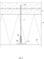
- FIGURE 1 illustrates schematically one type of brick tie.
- the brick tie is installed in the concrete element 1 and the cladding 2.
- the concrete element 1 mostly comprises a concrete frame 3 and an insulation layer 4 on the concrete frame 3.
- the cladding consists of bricks 5 and a mortar joint 6.
- the brick tie shown as an exploded view on the right side of the figure comprises a spike 7, a sleeve 8, a spacer 9 and a brick tie 10.
- the spike 7 is an elongated steel spike.
- the steel spike extends at its first end 11 through the insulation layer 4 into the concrete frame as shown in the figure.
- the sleeve 8 is attached at the end of the spike 7 opposite the concrete frame, the second end 12 and the spacer 9 is also attached to the second end 12 of the spike 7.
- the parts are positioned in the concrete frame such that the first end 11 of the spike is inside the concrete frame of the concrete element 1 and the second end 12 is near the surface of the insulation layer 4 opposite the concrete frame 3.
- the flange 13 of the sleeve 8 fastened to the second end 12 of the spike 7 is positioned against this surface. The flange 13 of the sleeve 8 thus locks the insulation layer 4 against the concrete frame 3.
- a spacer 9 is also attached to the second end 12 of the spike 7.
- the brick tie 10 is threaded into the fastening of the spacer 9.
- the brick tie 10 is a U-shaped tie with the tips of the arms of the U turned to the side.
- the brick tie 10 is dimensioned so that the brick 5 fits between its arms and the arm can be arranged into the mortar joint 6.
- the bent tips of the arms provide a good grip in the longitudinal direction of the brick tie.
- the spike 7, sleeve 8 and spacer 9 of FIGURES 1 to 4 are described in more detail in FIGURES 5a and 5b .
- the spike 7 is an elongated spike, the first end of which is provided with a form lock 14 for attaching to the concrete.
- the form lock is a wider part having a conical tip.
- Such a shape is easy to provide at e.g. the tip of a steel spike and the conical form facilitates pushing the spike 7 through the insulation layer 4.
- Alternative shapes include e.g. a transverse bulge structure, a wave-shaped form of the spike, a thread, spiral or toothing. Many suitable shapes are known in the field of concrete construction.
- the opposite end of the spike is provided with an M5 thread having a length of about 50 mm.
- the thread is the connection means for gripping 15 the sleeve 8 and at the same time a connection means for gripping 16 the spacer 9.
- Other locking methods can be used instead of the thread, such as cutting toothing, the locking used in zip ties or a spring steel tongue.
- the size of the thread can be varied.
- a thread is an advantageous locking method, because the plastic sleeve 8 can directly be threaded onto it without making a mating thread inside the sleeve.
- the spike 7 and the spacer 9 are usually made of steel, thread locking can be quickly and at low cost be formed into these parts, and additionally it is reliable and also allows removing parts, if necessary.
- the sleeve 8 comprises a body 17 having a cone 18 at the first end thereof and a flange 13 at the second end.
- the sleeve 8 is rotationally symmetrical about its central axis 19.
- the central axis 19 is the same for all parts 7, 8, 9, and thus they are coaxial after assembly.
- the function of the cone 18 is to facilitate the insertion of the sleeve 8 into the insulation layer 8, but other shapes can also be used.
- the flange 13 is a round, planar flange resembling a washer. Alternatively a polygonal or a wing-like flange could be used.
- a countersink hole 20 into the body 17 is provided at the outer surface of the flange 13 of the sleeve 8, ending in a shoulder 21 and extending therefrom as a hole 22 into the end of the cone 18 of the sleeve 8.
- the countersink hole 20 and the hole 22 are formed through the sleeve 8.
- the diameter of the hole 22 is dimensioned for the M5 thread of the spike 7 so that when the sleeve 8 is threaded onto the spike, the thread cuts threads into the hole.
- the countersink hole 20 is dimensioned so that the thread 12 at the second end of the spike 7 remains free inside the countersink hole 20 and the outer diameter of the spacer 9 fits inside the countersink hole 20.
- the spacer 9 is a hole nut, one end of which is provided with an M5 female thread and the other end with a loop having a hole.
- the M5 female thread forms the connection means of the spacer for attaching 23 the spike 7 and the loop with a hole forms a fastener for grip 24.
- the connection means for attaching 23 to the spike is preferably a thread corresponding with the spike, but as has been mentioned above, other fastening or locking methods can also be used. Especially the size and shape of the thread can be varied.
- the loop with a hole is an advantageous connecting means for grip 24.
- Alternative forms thereto could include a flange, truncated cone, hook/hooks, various quick locks and even a thread. However, a loop is easy to manufacture and providing grips thereto is easy and fast.
- FIGURES 1 to 4 provide examples of these. Such examples include, among others, a U-shaped brick tie 10, steel spike and one or more perforated bands, steel spike and one or more L-shaped grips, one arm of which is provided with a loop, or binding mesh. These grips can be modified and combined as necessary. Instead of a loop the spacer can also be provided with a spike, hook, larger loop or other shape functioning as a direct grip to the cladding.
- the invention is not limited to any certain material, but as at least parts of the cladding fastener are in ambient air, exposed to air and humidity, one advantageous material is austenitic steel. If there is no need for weatherization, other steel qualities can also be used. The most important feature limiting material selection is compatibility with concrete.
- the sleeve 8 is made of a plastic suitable for construction use or of light metal alloy, for example.
- FIGURES 1 to 4 Utilization methods according to some features of the invention are described in FIGURES 1 to 4 .
- FIGURE 1 The method of FIGURE 1 has already been partially described above. It is meant for laying a normal brick wall in connection with the concrete element, and the tie allows relative movement of the concrete element 1 and the cladding 2.
- this cladding fastener comprises the following parts:
- FIGURE 2 shows a brick tie for fastening a plaster net 25 on the insulation layer 4 of a concrete element 1.
- the spacer 9 is a plastic net sleeve 26 corresponding to the sleeve 7.
- the outer diameter of the net sleeve 26 is arranged to fit the countersink hole 20 of the sleeve 8, having am interior hole smaller than an M5 thread.
- a plaster net 25 is needed on the insulation layer 4 for attaching the plastering and keeping it uniform.
- the plaster net 25 is fastened to the thread of the spike 7 inside the sleeve 8 by means of threads.
- a hole is provided inside the net sleeve 26, smaller in diameter than an M5 thread.
- the plaster net 25 is positioned between the surface 4 of the insulation layer, flange 13 of the sleeve 8 and the flange of the net sleeve 25.
- this fastening method can be used for fastening other planar intermediate parts of surface finishes. Examples of these include e.g. sheet metal, foils and other similar surface claddings.
- FIGURE 3 shows a cladding fastener for laying tall bricks. It comprises a spike 7, sleeve 8 and a spacer 9 as described in FIGURE 5a .
- the grip consists of a connection spike 27 and two pieces of perforated band 28. One end of the connection spike 27 can be provided with a bulge 29 for preventing it from passing through the hole 9 in the spacer.
- the spike 7, sleeve 8 and spacer 9 are installed as described above, but the distance between them is arranged to suit the taller bricks. The distance can be e.g. 300 mm.
- Two spikes 7 with their plastic sleeves are installed through the insulation layer 4 at the element factory so that the distance between them in the vertical direction of the element 1 is about 300 mm.
- the bricklayer threads two pieces of perforated band 28 into a connection spike 27 with a length of about 350 mm and pushes the connection spike 28 through the holes of holed nuts used as spacers 9 so that the pieces of perforated band 28 remain between the spacers.
- the pieces of perforated band 28 are positioned into the mortar joints when laying bricks.
- FIGURE 4 shows a cladding fastener corresponding to that in FIGURE 3 , with the pieces of perforated band 28 being replaced by L-shaped grips 30. They are provided with hanging holes 31 at the end of one arm. This solution can be used when the distance between the grips can be increased or a larger vertical adjustment range is needed for arranging at the places of mortar joints.
- the cladding fastener described above is used especially in connection with concrete elements made by means of horizontal pouring.
- the spike 7 is fastened to the concrete frame 3 during pouring and the sleeve 8 is fastened to the spike 7.
- the production is made so that the plastic sleeve 8 is installed at one end 12 of the spike by means of an automatic machine into the correct depth so that the end of the spike 7 is inside the sleeve 8, about 10 mm below the upper surface of the flange 13.
- the thread of the spike 7 is visible for fastening to the spacer 9.
- Pre-cutting an M5 thread at the sleeve 8 is not necessary, as the thread is formed when threading the sleeve onto the steel spike 7.
- the countersink hole 20 of the sleeve 8 can be provided with a hexagonal Allen socket shape or other suitable shape for a key.
- the tools are selected to match the fastener.
- the prepared spikes 7 with their sleeves 8 are pushed through the insulation and the insulations are laid on the pouring table.
- the insulations are laid to form an insulation layer 4
- the concrete is poured over the insulation layer 4. Curing of the concrete locks the spikes in place and the sleeves 8 and the spikes 4 penetrating through the insulation layer attach the insulation layer to the concrete frame 3.
- the spacers 9 and the grips are fastened and the cladding is constructed at the construction site as described above.
- the spikes 7 with the sleeves 8 can first be placed on the pouring table either freely suspended by the flange 13 on the pouring table 32 and on a matrix prepared on the pouring table, subsequent to which the insulation layer is pressed onto the pouring table 32.
- the Allen socket or other mating surface for the thread tool can also be in the bet sleeve.
- FIGURE 7 shows one cladding fastener especially for fastening a plaster net.
- the features of this cladding fastener can be combined with the solutions described above, and correspondingly the features of the cladding fasteners described above can be applied in connection with the cladding fastener of figure 7 .
- the brick tie is installed in the concrete element 1 and the cladding 2.
- the concrete element 1 mostly comprises a concrete frame 3 and an insulation layer 4 on the concrete frame 3.
- the cladding 2 is plaster.
- the cladding fastener comprises a spike 7, sleeve 8, spacer 9 and a mesh support 36.
- the spike 7 is an elongated steel spike. The steel spike extends at its first end 11 through the insulation layer 4 into the concrete frame as shown in FIGURE 7 .
- the sleeve 8 is attached at the end of the spike 7 opposite the concrete frame, the second end 12, and the spacer 9, 26 is also attached to the second end 12 of the spike 7.
- the parts are positioned in the concrete frame such that the first end 11 of the spike is inside the concrete frame of the concrete element 1 and the second end 12 is near the surface of the insulation layer 4 opposite the concrete frame 3.
- the flange 13 of the sleeve 8 fastened to the second end 12 of the spike 7 is positioned against this surface.
- the flange 13 of the sleeve 8 thus locks the insulation layer 4 against the concrete frame 3.
- a spacer 9 is also attached to the second end 12 of the spike 7.
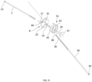
- the spike 7, sleeve 8 and spacer 9 of FIGURES 7 and 8 are described in more detail in FIGURE 9 .
- the spike 7 is an elongated spike the first end of which is provided with a form lock 14 for attaching to the concrete.
- the form lock is a wider part having a conical tip.
- Such a shape is easy to provide at e.g. the tip of a steel spike and the conical form facilitates pushing the spike 7 through the insulation layer 4.
- Alternative shapes include e.g. a transverse bulge structure, a wave-shaped form of the spike, a thread, spiral or toothing. Many suitable shapes are known in the field of concrete construction.
- the opposite end of the spike is provided with an M5 thread having a length of about 50 mm.
- the thread is the connection means 15 for gripping the sleeve 8 and simultaneously it is also the connection means 16 for gripping the spacer 9.
- Other locking methods can be used instead of the thread, such as cutting toothing, the locking used in zip ties or a spring steel tongue.
- the size of the thread can be varied.
- a thread is an advantageous locking method, because the plastic sleeve 8 can directly be threaded onto it without making a mating thread inside the sleeve.
- the spike 7 is usually made of steel, thread locking can be quickly and at low cost produced into these parts, and additionally it is reliable and also allows removing parts, if necessary.
- the sleeve 8 comprises a body 17 having a cone 18 at the first end thereof and a flange 13 at the second end.
- the sleeve 8 is rotationally symmetrical about its central axis 19.
- the central axis 19 is the same for all parts 7, 8, 9, and thus they are coaxial after assembly.
- the function of the cone 18 is to facilitate the insertion of the sleeve 8 into the insulation layer 8, but other shapes can also be used.
- the flange 13 is a round, planar flange resembling a washer. Alternatively a polygonal or a wing-like flange could be used.
- a countersink hole 20 into the body 17 is provided at the outer surface of the flange 13 of the sleeve 8, ending in a shoulder 21 and extending therefrom as a hole 22 into the end of the cone 18 of the sleeve 8.
- the countersink hole 20 and the hole 22 are formed through the sleeve 8.
- the diameter of the hole 22 is dimensioned for the M5 thread of the spike 7 so that when the sleeve 8 is threaded onto the spike, the thread cuts threads into the hole.
- the countersink hole 20 is dimensioned so that the thread 12 at the second end of the spike 7 remains free inside the countersink hole 20 and the outer diameter of the spacer 9 fits inside the countersink hole 20.
- the spacer 9 is a net sleeve 26 having a net flange 37 at the first end thereof and a cylindrical sleeve 38 at the second end.
- the cylindrical sleeve 38 forms the connection means of the spacer for attaching 23 the spike 7 and the net flange 37 forms a fastener for grip, which in this example is mesh support 36.
- the cylindrical sleeve 38 comprises a hole for the spike 7. If the net sleeve 26 is made of plastic, it is attached to the end 12 of the spike 7 similarly to the sleeve 8.
- connection means for connecting to the spike is advantageously a thread meshing with the spike, but as has been mentioned above, other attaching or locking methods can as well be used. Especially the size and shape of the thread can be varied.
- the sleeve 8 and the net sleeve 26 are made of a plastic suitable for construction use or of light metal alloy, for example.
- FIGURES 7 to 9 show a brick tie for fastening a plaster net 25 on the insulation layer 4 of a concrete element 1.
- the spacer 9 is a plastic net sleeve 26 corresponding to the sleeve 7.
- the outer diameter of the net sleeve 26 is arranged to fit the countersink hole 20 of the sleeve 8, having am interior hole smaller than an M5 thread.
- a plaster net 25 is needed on the insulation layer 4 for attaching the plastering and keeping it uniform.
- the plaster net 25 is fastened to the thread of the spike 7 inside the sleeve 8 by means of threads.
- a hole is provided inside the net sleeve 26, smaller in diameter than an M5 thread.
- the plaster net 25 is positioned between the surface 4 of the insulation layer, flange 13 of the sleeve 8 and the flange of the net sleeve 25.
- This attachment method can be used, in addition to attaching the plaster net, attaching other planar intermediate parts or surface finishes. These can include, for example, sheet metal, foils and other similar surface claddings.
- the cladding fastener is provided with a widened flange 13 forming a support shoulder 5.
- This support shoulder 33 can be formed e.g. so that the hole 22 of the sleeve 8 is positioned non-axially into a round flange, whereby the support shoulder is formed on the edge opposite to the hole 22.
- the support shoulder 33 can have any shape, such as an oval, triangle or a square.
- the support shoulder 33 is provided with a hole 10 for the support spike 34.
- the hole 10 for the support spike 34 is formed by a countersink hole, the bottom of which is skewed in relation to the axis of the spike 7 and the hole 35 of the support spike is perpendicular to the bottom of the bottom of the countersink hole.
- a support spike 34 is arranged into the hole 35 of the support spike, the support spike being at an angle to the axis of the spike 7 determined by the position of the bottom.
- the support spike 34 is to receive a load caused by the weight of the plaster, it is advantageously positioned directly above the spike 7 and its tip 39 is directed upwards, whereby the support spike 34 is under tensile stress.
- the support spike 34 will naturally receive loads in other positions as well.
- the tip of the support spike 34 is provided with a roughening, thread or other locking form for gripping the concrete.
- a bottom flange 40 being supported by the bottom of the support spike hole 35 that will position the support spike 34.
- the gripping means can be, for example, a fork, a penetrable surface or just a through-hole. A good positioning and support can, however, be achieved by means of a sufficiently long hole and countersink hole.
- the cladding fastener is provided with a positioning ring 41.
- the positioning ring 41 consists of an open ring 42 and four spike feet 43 formed on one edge of the open ring.
- the flange 13 of the sleeve 8 is provided with holes 44 for the spike feet corresponding with the spike feet 43.
- the positioning ring 41 can be fastened on the flange 13 by pushing the spike feet 43 through the spike feet holes 44 of the flange 13 to contact the insulation.
- the positioning ring 41 is positioned in its place and fastened to the insulation 4 by means of the spike feet 43.
- the shape of the positioning ring 41 can be different as well, but it must comprise a free opening or cutaway at the position of the hole 22 of the sleeve 8 for installing the net sleeve 26.
- the thickness of the positioning ring 41 defines the distance of the plaster net 25 from the insulation 4.
- the cladding fastener described above is used especially in connection with concrete elements made by means of horizontal pouring.
- the spikes 7 are fastened to the concrete frame 3 during pouring and the sleeve 8 is fastened to the spike 7.
- the production is made so that the plastic sleeve 8 is installed at one end 12 of the spike by means of an automatic machine into the correct depth so that the end of the spike 7 is inside the sleeve 8, about 10 mm below the upper surface of the flange 13.
- the thread of the spike 7 is visible for fastening to the spacer 9.
- Pre-cutting an M5 thread at the sleeve 8 is not necessary, as the thread is formed when threading the sleeve onto the steel spike 7.
- the countersink hole 20 of the sleeve 8 can be provided with a hexagonal Allen socket shape or other suitable shape for a key.
- the tools are selected to match the fastener.
- the prepared spike 7 with its sleeve 8 is pushed through the insulation and the support spike 34 is pushed in its place, after which the insulations are laid on the pouring table.
- the concrete is poured over the insulation layer 4.
- the curing concrete locks the spikes in place and the sleeves 8 and the support spikes 34 and the spikes 8 penetrating through the insulation layer 4 attach the insulation layer to the concrete frame 3.
- the spacers 9 and the positioning ring 41 are fastened and the cladding is manufactured at the construction site by pushing the positioning rings 41 into the flanges.
- the plaster net will be arranged between the positioning ring 41 and the flange 27 of the net sleeve 26 as shown in figure 2 .
- the invention can be used in construction industry.
Landscapes
- Engineering & Computer Science (AREA)
- Architecture (AREA)
- Civil Engineering (AREA)
- Structural Engineering (AREA)
- Physics & Mathematics (AREA)
- Electromagnetism (AREA)
- Ceramic Engineering (AREA)
- Manufacturing & Machinery (AREA)
- Chemical & Material Sciences (AREA)
- Mechanical Engineering (AREA)
- Acoustics & Sound (AREA)
- Joining Of Building Structures In Genera (AREA)
- Connection Of Plates (AREA)
Claims (16)
- Élément de fixation de parement, comprenant :- une pointe allongée (7),- un manchon (8) présentant un corps (17),- la première extrémité (11) de la pointe (7) comprenant un dispositif de blocage de coffrage (14) destiné à être fixé à une charpente en béton (3) d'un élément en béton (1), et- une entretoise (9), dans lequel- la seconde extrémité de la pointe (7) est munie d'un moyen de liaison (15) destiné à être fixé au manchon (8) et d'un moyen de liaison (16) destiné à être fixé à l'entretoise (9), et- l'entretoise (9) est munie d'un moyen de liaison (23) de l'entretoise destiné à être fixé à la pointe (7) et d'un élément de fixation pour un élément de préhension (24), caractérisé en ce que- le manchon présente une bride (13) s'étendant sur le côté depuis le corps (17) et un trou fraisé (20) destiné à correspondre au diamètre externe de l'entretoise (9), le trou fraisé (20) se terminant par un épaulement (21) et s'étendant à partir de celui-ci sous forme d'un trou (22) à travers le manchon (8).
- Élément de fixation de parement selon la revendication 1, caractérisé en ce que le moyen de liaison (16) de la pointe (7) destiné à être fixé à l'entretoise (9) est un filetage et le moyen de liaison (23) de l'entretoise destiné à être fixé à la pointe est un filetage.
- Élément de fixation de parement selon la revendication 2, caractérisé en ce que le moyen de liaison (15) de la pointe (7) destiné à être fixé au manchon (8) est un filetage destiné à la fixation de l'entretoise (9) de la pointe (7).
- Élément de fixation de parement selon l'une quelconque des revendications précédentes, caractérisé en ce que l'entretoise (9) est un écrou à trou dont la première extrémité est munie d'un filetage femelle destiné à être fixé à la pointe (7) et la seconde extrémité opposée est munie d'une boucle formant un trou.
- Élément de fixation de parement selon l'une quelconque des revendications 1 à 3, caractérisé en ce que l'entretoise (9) est un écrou à trou dont la première extrémité est munie d'un filetage femelle destiné à être fixé à la pointe (7) et la seconde extrémité opposée est munie d'une bride s'étendant sur le côté par rapport à la direction axiale du filetage femelle.
- Élément de fixation de parement selon l'une quelconque des revendications précédentes, caractérisé en ce que l'élément de fixation de parement comprend un élément de préhension, l'élément de préhension étant, par exemple, au moins l'un des éléments suivants :- une agrafe à brique en U (10),- une pointe de liaison (27) et au moins un morceau de bande perforée (28),- une pointe de liaison (27) et au moins un élément de préhension en L(30) dont un bras est muni d'une boucle (31) ou- un filet d'attache (25).
- Élément de fixation de parement selon la revendication 1, caractérisé en ce que l'entretoise (9) est un écrou à trou dont la première extrémité est munie d'un filetage femelle destiné à être fixé à la pointe (7) et la seconde extrémité opposée est munie d'une barre s'étendant de manière coaxiale à la direction axiale du filetage femelle.
- Élément de fixation de parement selon l'une quelconque des revendications précédentes, dans lequel la première extrémité (11) de la pointe (7) comprend un dispositif de blocage de coffrage (14) destiné à être fixé à une charpente en béton (3) de l'élément en béton (1), caractérisé en que- l'élément de fixation de parement comprend une entretoise (9) et une pointe de support (6) et- la seconde extrémité de la pointe (7) est munie d'un moyen de liaison (15) destiné à être fixé au manchon (8) et d'un moyen de liaison (28) destiné à être fixé à l'entretoise (9),- l'entretoise (9) est munie d'un moyen de liaison de l'entretoise destiné à être fixé à la pointe (23) et d'un élément de fixation pour élément de préhension (24, 27), et- la bride (13) forme un épaulement de support s'étendant sur le côté et présentant un moyen de préhension (10) pour la pointe de support (6).
- Élément de fixation de parement selon la revendication 8, caractérisé en ce que l'élément de fixation de parement comprend un anneau de positionnement (31) présentant un moyen de liaison (33) destiné à être fixé au manchon (8) et un trou au niveau de la position du moyen de liaison (22) se fixant à l'entretoise (9, 26).
- Élément de fixation de parement selon la revendication 1 ou 2, caractérisé en ce que le moyen de préhension pour la pointe de support (6) est un trou fraisé présentant un fond et muni d'un trou (10) pour la pointe de support (6).
- Procédé consistant à munir un élément en béton d'un élément de fixation de parement, en utilisant un élément de fixation de parement selon la revendication 1, dans lequel- une pointe (7) est fixée au corps (17) d'un manchon (8) comprenant un corps (17) et une bride (13),- la pointe (7) équipée du manchon (8) est poussée à travers une couche d'isolation (4) de telle sorte que la première extrémité de la pointe s'étende en dehors de la couche isolante (4), et- une couche de béton est coulée sur la couche d'isolation (4), selon lequel la première extrémité (11) de la pointe (7) est fixée par le béton durcissant et la bride (13) du manchon (8) est positionnée contre la surface de la couche d'isolation (4) opposée à la couche de béton, bloquant la couche d'isolation (4) sur le béton au moyen du manchon (8) et de la pointe (7).
- Procédé selon la revendication 11, caractérisé en ce que le manchon (8) est fixé à la pointe (7) au moyen d'un raccord fileté.
- Procédé selon la revendication 12, caractérisé en ce que le manchon (8) est fixé à la pointe (7) au moyen d'un outil de filetage automatique.
- Procédé selon l'une quelconque des revendications 11 à 13, caractérisé en ce que la pointe (7) est d'abord poussée à travers la couche d'isolation (4), après quoi la couche d'isolation (4) est positionnée sur la table de coulée (32) avec la pointe (7).
- Procédé selon l'une quelconque des revendications 11 à 13, caractérisé en ce que la pointe (7) est positionnée sur la table de coulée et la couche d'isolation (4) est pressée pour venir en contact avec la pointe (7) sur la table de coulée (32).
- Procédé selon l'une quelconque des revendications 11 à 15, caractérisé en ce qu'une pointe de support (34) est pressée dans la bride (13) et la couche d'isolation (4).
Applications Claiming Priority (2)
| Application Number | Priority Date | Filing Date | Title |
|---|---|---|---|
| FI20206160A FI130822B1 (fi) | 2020-11-16 | 2020-11-16 | Betonielementin verhouskiinnike ja menetelmä betonielementin varustelemiseksi verhouskiinnikkeellä |
| FIU20204176U FI13121Y1 (fi) | 2020-11-16 | 2020-12-23 | Betonielementin verhouskiinnike |
Publications (2)
| Publication Number | Publication Date |
|---|---|
| EP4001534A1 EP4001534A1 (fr) | 2022-05-25 |
| EP4001534B1 true EP4001534B1 (fr) | 2023-11-15 |
Family
ID=80628447
Family Applications (1)
| Application Number | Title | Priority Date | Filing Date |
|---|---|---|---|
| EP21208118.6A Active EP4001534B1 (fr) | 2020-11-16 | 2021-11-15 | Fixation de parement et méthode procurant une structure en béton munie d'une fixation de parement |
Country Status (3)
| Country | Link |
|---|---|
| EP (1) | EP4001534B1 (fr) |
| FI (2) | FI130822B1 (fr) |
| PL (1) | PL4001534T3 (fr) |
Citations (1)
| Publication number | Priority date | Publication date | Assignee | Title |
|---|---|---|---|---|
| EP3462044A1 (fr) * | 2017-09-27 | 2019-04-03 | Van Roij Fasteners Europe B.V. | Élément de fixation |
Family Cites Families (4)
| Publication number | Priority date | Publication date | Assignee | Title |
|---|---|---|---|---|
| US8109706B2 (en) * | 2007-11-28 | 2012-02-07 | Richards Joseph P | Composite fastener, belly nut, tie system and/or method for reducing heat transfer through a building envelope |
| GB2494135B (en) * | 2011-08-30 | 2017-06-14 | Magmatech Ltd | Wall tie |
| DE202012001461U1 (de) * | 2012-02-15 | 2012-03-14 | Mcon Gmbh | Halterungsanordnung |
| KR102069446B1 (ko) * | 2018-09-11 | 2020-01-22 | 목포대학교산학협력단 | 슬라이드 포켓 압입 클립이 적용된 다중 록킹존 형성을 통한 벽돌벽체 내진보강 장치 및 이를 이용한 비구조치장벽체의 시공 방법 |
-
2020
- 2020-11-16 FI FI20206160A patent/FI130822B1/fi active
- 2020-12-23 FI FIU20204176U patent/FI13121Y1/fi active IP Right Grant
-
2021
- 2021-11-15 PL PL21208118.6T patent/PL4001534T3/pl unknown
- 2021-11-15 EP EP21208118.6A patent/EP4001534B1/fr active Active
Patent Citations (1)
| Publication number | Priority date | Publication date | Assignee | Title |
|---|---|---|---|---|
| EP3462044A1 (fr) * | 2017-09-27 | 2019-04-03 | Van Roij Fasteners Europe B.V. | Élément de fixation |
Also Published As
| Publication number | Publication date |
|---|---|
| FI20206160A1 (fi) | 2022-05-17 |
| FI130822B1 (fi) | 2024-04-08 |
| FI13121Y1 (fi) | 2022-02-16 |
| EP4001534A1 (fr) | 2022-05-25 |
| PL4001534T3 (pl) | 2024-04-15 |
Similar Documents
| Publication | Publication Date | Title |
|---|---|---|
| CA2650667A1 (fr) | Systeme de plancher et de mur composite | |
| US20140059968A1 (en) | Apparatus to Tie Forms to Existing Structures | |
| EP4001534B1 (fr) | Fixation de parement et méthode procurant une structure en béton munie d'une fixation de parement | |
| DE20317103U1 (de) | Befestigungselement und Befestigungssystem für Gebäudebekleidungen | |
| AU2009257198B2 (en) | Composite panel, connector and related method | |
| KR200291531Y1 (ko) | 파이프 서포트용 고정핀 | |
| KR101132685B1 (ko) | 철근 연결구 | |
| KR101127765B1 (ko) | 와이어앙카 및 와이어 앙카 시공방법 | |
| CN220266964U (zh) | 带钢筋免拆非金属底板一体化楼承板及相应楼面结构 | |
| CN119266399A (zh) | 装配自锁式外墙保温锚栓及方法 | |
| JP2013163954A (ja) | 中空コンクリート基盤の施工方法 | |
| US20060144007A1 (en) | Coil bar anchor | |
| KR100635560B1 (ko) | 조적벽돌 보강장치 | |
| AT523434B1 (de) | Verankerung für Betonfertigteile | |
| DE102012003522A1 (de) | Verbindungselement | |
| CN223330019U (zh) | 装配自锁式外墙保温锚栓 | |
| US20260097931A1 (en) | Lifting System for Wooden Construction Elements | |
| CN113356477B (zh) | 一种锚固型分体式连接件及其安装方法 | |
| KR100306028B1 (ko) | 강관말뚝 머리부와 콘크리트 기초의 결합구조 | |
| RU2007103357A (ru) | Составной анкерный болт и способ монтажа анкерного болта | |
| KR200261782Y1 (ko) | 치장벽돌 연결보강재 | |
| JPH0232722Y2 (fr) | ||
| CN211341403U (zh) | 一种吊装稳定性强的石膏预制墙板 | |
| KR100797486B1 (ko) | 천정 구조물 지지용 내열성 인서트 | |
| EP1853778B1 (fr) | Procédé pour attacher des éléments de fixation à une prédalle |
Legal Events
| Date | Code | Title | Description |
|---|---|---|---|
| PUAI | Public reference made under article 153(3) epc to a published international application that has entered the european phase |
Free format text: ORIGINAL CODE: 0009012 |
|
| STAA | Information on the status of an ep patent application or granted ep patent |
Free format text: STATUS: THE APPLICATION HAS BEEN PUBLISHED |
|
| AK | Designated contracting states |
Kind code of ref document: A1 Designated state(s): AL AT BE BG CH CY CZ DE DK EE ES FI FR GB GR HR HU IE IS IT LI LT LU LV MC MK MT NL NO PL PT RO RS SE SI SK SM TR |
|
| STAA | Information on the status of an ep patent application or granted ep patent |
Free format text: STATUS: REQUEST FOR EXAMINATION WAS MADE |
|
| 17P | Request for examination filed |
Effective date: 20221125 |
|
| RBV | Designated contracting states (corrected) |
Designated state(s): AL AT BE BG CH CY CZ DE DK EE ES FI FR GB GR HR HU IE IS IT LI LT LU LV MC MK MT NL NO PL PT RO RS SE SI SK SM TR |
|
| GRAP | Despatch of communication of intention to grant a patent |
Free format text: ORIGINAL CODE: EPIDOSNIGR1 |
|
| STAA | Information on the status of an ep patent application or granted ep patent |
Free format text: STATUS: GRANT OF PATENT IS INTENDED |
|
| INTG | Intention to grant announced |
Effective date: 20230602 |
|
| GRAS | Grant fee paid |
Free format text: ORIGINAL CODE: EPIDOSNIGR3 |
|
| GRAA | (expected) grant |
Free format text: ORIGINAL CODE: 0009210 |
|
| STAA | Information on the status of an ep patent application or granted ep patent |
Free format text: STATUS: THE PATENT HAS BEEN GRANTED |
|
| AK | Designated contracting states |
Kind code of ref document: B1 Designated state(s): AL AT BE BG CH CY CZ DE DK EE ES FI FR GB GR HR HU IE IS IT LI LT LU LV MC MK MT NL NO PL PT RO RS SE SI SK SM TR |
|
| REG | Reference to a national code |
Ref country code: CH Ref legal event code: EP Ref country code: GB Ref legal event code: FG4D |
|
| REG | Reference to a national code |
Ref country code: DE Ref legal event code: R096 Ref document number: 602021006820 Country of ref document: DE |
|
| REG | Reference to a national code |
Ref country code: IE Ref legal event code: FG4D |
|
| REG | Reference to a national code |
Ref country code: SE Ref legal event code: TRGR |
|
| REG | Reference to a national code |
Ref country code: LT Ref legal event code: MG9D |
|
| REG | Reference to a national code |
Ref country code: NL Ref legal event code: MP Effective date: 20231115 |
|
| PG25 | Lapsed in a contracting state [announced via postgrant information from national office to epo] |
Ref country code: GR Free format text: LAPSE BECAUSE OF FAILURE TO SUBMIT A TRANSLATION OF THE DESCRIPTION OR TO PAY THE FEE WITHIN THE PRESCRIBED TIME-LIMIT Effective date: 20240216 |
|
| PG25 | Lapsed in a contracting state [announced via postgrant information from national office to epo] |
Ref country code: IS Free format text: LAPSE BECAUSE OF FAILURE TO SUBMIT A TRANSLATION OF THE DESCRIPTION OR TO PAY THE FEE WITHIN THE PRESCRIBED TIME-LIMIT Effective date: 20240315 |
|
| PG25 | Lapsed in a contracting state [announced via postgrant information from national office to epo] |
Ref country code: LT Free format text: LAPSE BECAUSE OF FAILURE TO SUBMIT A TRANSLATION OF THE DESCRIPTION OR TO PAY THE FEE WITHIN THE PRESCRIBED TIME-LIMIT Effective date: 20231115 |
|
| REG | Reference to a national code |
Ref country code: AT Ref legal event code: MK05 Ref document number: 1631901 Country of ref document: AT Kind code of ref document: T Effective date: 20231115 |
|
| PG25 | Lapsed in a contracting state [announced via postgrant information from national office to epo] |
Ref country code: NL Free format text: LAPSE BECAUSE OF FAILURE TO SUBMIT A TRANSLATION OF THE DESCRIPTION OR TO PAY THE FEE WITHIN THE PRESCRIBED TIME-LIMIT Effective date: 20231115 |
|
| PG25 | Lapsed in a contracting state [announced via postgrant information from national office to epo] |
Ref country code: AT Free format text: LAPSE BECAUSE OF FAILURE TO SUBMIT A TRANSLATION OF THE DESCRIPTION OR TO PAY THE FEE WITHIN THE PRESCRIBED TIME-LIMIT Effective date: 20231115 |
|
| PG25 | Lapsed in a contracting state [announced via postgrant information from national office to epo] |
Ref country code: ES Free format text: LAPSE BECAUSE OF FAILURE TO SUBMIT A TRANSLATION OF THE DESCRIPTION OR TO PAY THE FEE WITHIN THE PRESCRIBED TIME-LIMIT Effective date: 20231115 |
|
| PG25 | Lapsed in a contracting state [announced via postgrant information from national office to epo] |
Ref country code: NL Free format text: LAPSE BECAUSE OF FAILURE TO SUBMIT A TRANSLATION OF THE DESCRIPTION OR TO PAY THE FEE WITHIN THE PRESCRIBED TIME-LIMIT Effective date: 20231115 Ref country code: LT Free format text: LAPSE BECAUSE OF FAILURE TO SUBMIT A TRANSLATION OF THE DESCRIPTION OR TO PAY THE FEE WITHIN THE PRESCRIBED TIME-LIMIT Effective date: 20231115 Ref country code: IS Free format text: LAPSE BECAUSE OF FAILURE TO SUBMIT A TRANSLATION OF THE DESCRIPTION OR TO PAY THE FEE WITHIN THE PRESCRIBED TIME-LIMIT Effective date: 20240315 Ref country code: GR Free format text: LAPSE BECAUSE OF FAILURE TO SUBMIT A TRANSLATION OF THE DESCRIPTION OR TO PAY THE FEE WITHIN THE PRESCRIBED TIME-LIMIT Effective date: 20240216 Ref country code: ES Free format text: LAPSE BECAUSE OF FAILURE TO SUBMIT A TRANSLATION OF THE DESCRIPTION OR TO PAY THE FEE WITHIN THE PRESCRIBED TIME-LIMIT Effective date: 20231115 Ref country code: BG Free format text: LAPSE BECAUSE OF FAILURE TO SUBMIT A TRANSLATION OF THE DESCRIPTION OR TO PAY THE FEE WITHIN THE PRESCRIBED TIME-LIMIT Effective date: 20240215 Ref country code: AT Free format text: LAPSE BECAUSE OF FAILURE TO SUBMIT A TRANSLATION OF THE DESCRIPTION OR TO PAY THE FEE WITHIN THE PRESCRIBED TIME-LIMIT Effective date: 20231115 Ref country code: PT Free format text: LAPSE BECAUSE OF FAILURE TO SUBMIT A TRANSLATION OF THE DESCRIPTION OR TO PAY THE FEE WITHIN THE PRESCRIBED TIME-LIMIT Effective date: 20240315 |
|
| PG25 | Lapsed in a contracting state [announced via postgrant information from national office to epo] |
Ref country code: RS Free format text: LAPSE BECAUSE OF FAILURE TO SUBMIT A TRANSLATION OF THE DESCRIPTION OR TO PAY THE FEE WITHIN THE PRESCRIBED TIME-LIMIT Effective date: 20231115 Ref country code: NO Free format text: LAPSE BECAUSE OF FAILURE TO SUBMIT A TRANSLATION OF THE DESCRIPTION OR TO PAY THE FEE WITHIN THE PRESCRIBED TIME-LIMIT Effective date: 20240215 Ref country code: LV Free format text: LAPSE BECAUSE OF FAILURE TO SUBMIT A TRANSLATION OF THE DESCRIPTION OR TO PAY THE FEE WITHIN THE PRESCRIBED TIME-LIMIT Effective date: 20231115 Ref country code: HR Free format text: LAPSE BECAUSE OF FAILURE TO SUBMIT A TRANSLATION OF THE DESCRIPTION OR TO PAY THE FEE WITHIN THE PRESCRIBED TIME-LIMIT Effective date: 20231115 |
|
| PG25 | Lapsed in a contracting state [announced via postgrant information from national office to epo] |
Ref country code: DK Free format text: LAPSE BECAUSE OF FAILURE TO SUBMIT A TRANSLATION OF THE DESCRIPTION OR TO PAY THE FEE WITHIN THE PRESCRIBED TIME-LIMIT Effective date: 20231115 |
|
| PG25 | Lapsed in a contracting state [announced via postgrant information from national office to epo] |
Ref country code: LU Free format text: LAPSE BECAUSE OF NON-PAYMENT OF DUE FEES Effective date: 20231115 |
|
| PG25 | Lapsed in a contracting state [announced via postgrant information from national office to epo] |
Ref country code: CZ Free format text: LAPSE BECAUSE OF FAILURE TO SUBMIT A TRANSLATION OF THE DESCRIPTION OR TO PAY THE FEE WITHIN THE PRESCRIBED TIME-LIMIT Effective date: 20231115 |
|
| PG25 | Lapsed in a contracting state [announced via postgrant information from national office to epo] |
Ref country code: SK Free format text: LAPSE BECAUSE OF FAILURE TO SUBMIT A TRANSLATION OF THE DESCRIPTION OR TO PAY THE FEE WITHIN THE PRESCRIBED TIME-LIMIT Effective date: 20231115 |
|
| PG25 | Lapsed in a contracting state [announced via postgrant information from national office to epo] |
Ref country code: SM Free format text: LAPSE BECAUSE OF FAILURE TO SUBMIT A TRANSLATION OF THE DESCRIPTION OR TO PAY THE FEE WITHIN THE PRESCRIBED TIME-LIMIT Effective date: 20231115 Ref country code: SK Free format text: LAPSE BECAUSE OF FAILURE TO SUBMIT A TRANSLATION OF THE DESCRIPTION OR TO PAY THE FEE WITHIN THE PRESCRIBED TIME-LIMIT Effective date: 20231115 Ref country code: RO Free format text: LAPSE BECAUSE OF FAILURE TO SUBMIT A TRANSLATION OF THE DESCRIPTION OR TO PAY THE FEE WITHIN THE PRESCRIBED TIME-LIMIT Effective date: 20231115 Ref country code: LU Free format text: LAPSE BECAUSE OF NON-PAYMENT OF DUE FEES Effective date: 20231115 Ref country code: IT Free format text: LAPSE BECAUSE OF FAILURE TO SUBMIT A TRANSLATION OF THE DESCRIPTION OR TO PAY THE FEE WITHIN THE PRESCRIBED TIME-LIMIT Effective date: 20231115 Ref country code: EE Free format text: LAPSE BECAUSE OF FAILURE TO SUBMIT A TRANSLATION OF THE DESCRIPTION OR TO PAY THE FEE WITHIN THE PRESCRIBED TIME-LIMIT Effective date: 20231115 Ref country code: DK Free format text: LAPSE BECAUSE OF FAILURE TO SUBMIT A TRANSLATION OF THE DESCRIPTION OR TO PAY THE FEE WITHIN THE PRESCRIBED TIME-LIMIT Effective date: 20231115 Ref country code: CZ Free format text: LAPSE BECAUSE OF FAILURE TO SUBMIT A TRANSLATION OF THE DESCRIPTION OR TO PAY THE FEE WITHIN THE PRESCRIBED TIME-LIMIT Effective date: 20231115 |
|
| REG | Reference to a national code |
Ref country code: BE Ref legal event code: MM Effective date: 20231130 |
|
| REG | Reference to a national code |
Ref country code: DE Ref legal event code: R097 Ref document number: 602021006820 Country of ref document: DE |
|
| PG25 | Lapsed in a contracting state [announced via postgrant information from national office to epo] |
Ref country code: MC Free format text: LAPSE BECAUSE OF FAILURE TO SUBMIT A TRANSLATION OF THE DESCRIPTION OR TO PAY THE FEE WITHIN THE PRESCRIBED TIME-LIMIT Effective date: 20231115 |
|
| PG25 | Lapsed in a contracting state [announced via postgrant information from national office to epo] |
Ref country code: MC Free format text: LAPSE BECAUSE OF FAILURE TO SUBMIT A TRANSLATION OF THE DESCRIPTION OR TO PAY THE FEE WITHIN THE PRESCRIBED TIME-LIMIT Effective date: 20231115 |
|
| REG | Reference to a national code |
Ref country code: IE Ref legal event code: MM4A |
|
| PLBE | No opposition filed within time limit |
Free format text: ORIGINAL CODE: 0009261 |
|
| STAA | Information on the status of an ep patent application or granted ep patent |
Free format text: STATUS: NO OPPOSITION FILED WITHIN TIME LIMIT |
|
| PG25 | Lapsed in a contracting state [announced via postgrant information from national office to epo] |
Ref country code: IE Free format text: LAPSE BECAUSE OF NON-PAYMENT OF DUE FEES Effective date: 20231115 |
|
| PG25 | Lapsed in a contracting state [announced via postgrant information from national office to epo] |
Ref country code: BE Free format text: LAPSE BECAUSE OF NON-PAYMENT OF DUE FEES Effective date: 20231130 |
|
| PG25 | Lapsed in a contracting state [announced via postgrant information from national office to epo] |
Ref country code: FR Free format text: LAPSE BECAUSE OF NON-PAYMENT OF DUE FEES Effective date: 20240115 |
|
| 26N | No opposition filed |
Effective date: 20240819 |
|
| PG25 | Lapsed in a contracting state [announced via postgrant information from national office to epo] |
Ref country code: SI Free format text: LAPSE BECAUSE OF FAILURE TO SUBMIT A TRANSLATION OF THE DESCRIPTION OR TO PAY THE FEE WITHIN THE PRESCRIBED TIME-LIMIT Effective date: 20231115 |
|
| PG25 | Lapsed in a contracting state [announced via postgrant information from national office to epo] |
Ref country code: SI Free format text: LAPSE BECAUSE OF FAILURE TO SUBMIT A TRANSLATION OF THE DESCRIPTION OR TO PAY THE FEE WITHIN THE PRESCRIBED TIME-LIMIT Effective date: 20231115 Ref country code: IE Free format text: LAPSE BECAUSE OF NON-PAYMENT OF DUE FEES Effective date: 20231115 Ref country code: FR Free format text: LAPSE BECAUSE OF NON-PAYMENT OF DUE FEES Effective date: 20240115 Ref country code: BE Free format text: LAPSE BECAUSE OF NON-PAYMENT OF DUE FEES Effective date: 20231130 |
|
| REG | Reference to a national code |
Ref country code: CH Ref legal event code: PL |
|
| PG25 | Lapsed in a contracting state [announced via postgrant information from national office to epo] |
Ref country code: FI Free format text: LAPSE BECAUSE OF FAILURE TO SUBMIT A TRANSLATION OF THE DESCRIPTION OR TO PAY THE FEE WITHIN THE PRESCRIBED TIME-LIMIT Effective date: 20231115 |
|
| REG | Reference to a national code |
Ref country code: CH Ref legal event code: PL |
|
| PG25 | Lapsed in a contracting state [announced via postgrant information from national office to epo] |
Ref country code: CH Free format text: LAPSE BECAUSE OF NON-PAYMENT OF DUE FEES Effective date: 20241130 |
|
| PG25 | Lapsed in a contracting state [announced via postgrant information from national office to epo] |
Ref country code: CY Free format text: LAPSE BECAUSE OF FAILURE TO SUBMIT A TRANSLATION OF THE DESCRIPTION OR TO PAY THE FEE WITHIN THE PRESCRIBED TIME-LIMIT; INVALID AB INITIO Effective date: 20211115 |
|
| PG25 | Lapsed in a contracting state [announced via postgrant information from national office to epo] |
Ref country code: TR Free format text: LAPSE BECAUSE OF FAILURE TO SUBMIT A TRANSLATION OF THE DESCRIPTION OR TO PAY THE FEE WITHIN THE PRESCRIBED TIME-LIMIT Effective date: 20231115 |
|
| PGFP | Annual fee paid to national office [announced via postgrant information from national office to epo] |
Ref country code: DE Payment date: 20251119 Year of fee payment: 5 |
|
| PGFP | Annual fee paid to national office [announced via postgrant information from national office to epo] |
Ref country code: SE Payment date: 20251119 Year of fee payment: 5 |
|
| PGFP | Annual fee paid to national office [announced via postgrant information from national office to epo] |
Ref country code: PL Payment date: 20251107 Year of fee payment: 5 |
|
| PG25 | Lapsed in a contracting state [announced via postgrant information from national office to epo] |
Ref country code: HU Free format text: LAPSE BECAUSE OF FAILURE TO SUBMIT A TRANSLATION OF THE DESCRIPTION OR TO PAY THE FEE WITHIN THE PRESCRIBED TIME-LIMIT; INVALID AB INITIO Effective date: 20211115 |