EP4001592A1 - Cmc-schaufelbogensegment mit freitragendem holm - Google Patents
Cmc-schaufelbogensegment mit freitragendem holm Download PDFInfo
- Publication number
- EP4001592A1 EP4001592A1 EP21205653.5A EP21205653A EP4001592A1 EP 4001592 A1 EP4001592 A1 EP 4001592A1 EP 21205653 A EP21205653 A EP 21205653A EP 4001592 A1 EP4001592 A1 EP 4001592A1
- Authority
- EP
- European Patent Office
- Prior art keywords
- hollow
- arc segment
- spar
- leg
- recited
- Prior art date
- Legal status (The legal status is an assumption and is not a legal conclusion. Google has not performed a legal analysis and makes no representation as to the accuracy of the status listed.)
- Pending
Links
Images


Classifications
-
- F—MECHANICAL ENGINEERING; LIGHTING; HEATING; WEAPONS; BLASTING
- F01—MACHINES OR ENGINES IN GENERAL; ENGINE PLANTS IN GENERAL; STEAM ENGINES
- F01D—NON-POSITIVE DISPLACEMENT MACHINES OR ENGINES, e.g. STEAM TURBINES
- F01D5/00—Blades; Blade-carrying members; Heating, heat-insulating, cooling or antivibration means on the blades or the members
- F01D5/12—Blades
- F01D5/14—Form or construction
- F01D5/18—Hollow blades, i.e. blades with cooling or heating channels or cavities; Heating, heat-insulating or cooling means on blades
- F01D5/187—Convection cooling
-
- F—MECHANICAL ENGINEERING; LIGHTING; HEATING; WEAPONS; BLASTING
- F01—MACHINES OR ENGINES IN GENERAL; ENGINE PLANTS IN GENERAL; STEAM ENGINES
- F01D—NON-POSITIVE DISPLACEMENT MACHINES OR ENGINES, e.g. STEAM TURBINES
- F01D5/00—Blades; Blade-carrying members; Heating, heat-insulating, cooling or antivibration means on the blades or the members
- F01D5/12—Blades
- F01D5/14—Form or construction
- F01D5/147—Construction, i.e. structural features, e.g. of weight-saving hollow blades
-
- F—MECHANICAL ENGINEERING; LIGHTING; HEATING; WEAPONS; BLASTING
- F01—MACHINES OR ENGINES IN GENERAL; ENGINE PLANTS IN GENERAL; STEAM ENGINES
- F01D—NON-POSITIVE DISPLACEMENT MACHINES OR ENGINES, e.g. STEAM TURBINES
- F01D5/00—Blades; Blade-carrying members; Heating, heat-insulating, cooling or antivibration means on the blades or the members
- F01D5/12—Blades
- F01D5/14—Form or construction
- F01D5/18—Hollow blades, i.e. blades with cooling or heating channels or cavities; Heating, heat-insulating or cooling means on blades
- F01D5/187—Convection cooling
- F01D5/188—Convection cooling with an insert in the blade cavity to guide the cooling fluid, e.g. forming a separation wall
- F01D5/189—Convection cooling with an insert in the blade cavity to guide the cooling fluid, e.g. forming a separation wall the insert having a tubular cross-section, e.g. airfoil shape
-
- F—MECHANICAL ENGINEERING; LIGHTING; HEATING; WEAPONS; BLASTING
- F01—MACHINES OR ENGINES IN GENERAL; ENGINE PLANTS IN GENERAL; STEAM ENGINES
- F01D—NON-POSITIVE DISPLACEMENT MACHINES OR ENGINES, e.g. STEAM TURBINES
- F01D5/00—Blades; Blade-carrying members; Heating, heat-insulating, cooling or antivibration means on the blades or the members
- F01D5/12—Blades
- F01D5/28—Selecting particular materials; Particular measures relating thereto; Measures against erosion or corrosion
- F01D5/284—Selection of ceramic materials
-
- F—MECHANICAL ENGINEERING; LIGHTING; HEATING; WEAPONS; BLASTING
- F01—MACHINES OR ENGINES IN GENERAL; ENGINE PLANTS IN GENERAL; STEAM ENGINES
- F01D—NON-POSITIVE DISPLACEMENT MACHINES OR ENGINES, e.g. STEAM TURBINES
- F01D9/00—Stators
- F01D9/02—Nozzles; Nozzle boxes; Stator blades; Guide conduits, e.g. individual nozzles
- F01D9/04—Nozzles; Nozzle boxes; Stator blades; Guide conduits, e.g. individual nozzles forming ring or sector
- F01D9/041—Nozzles; Nozzle boxes; Stator blades; Guide conduits, e.g. individual nozzles forming ring or sector using blades
-
- F—MECHANICAL ENGINEERING; LIGHTING; HEATING; WEAPONS; BLASTING
- F01—MACHINES OR ENGINES IN GENERAL; ENGINE PLANTS IN GENERAL; STEAM ENGINES
- F01D—NON-POSITIVE DISPLACEMENT MACHINES OR ENGINES, e.g. STEAM TURBINES
- F01D9/00—Stators
- F01D9/06—Fluid supply conduits to nozzles or the like
- F01D9/065—Fluid supply or removal conduits traversing the working fluid flow, e.g. for lubrication-, cooling-, or sealing fluids
-
- F—MECHANICAL ENGINEERING; LIGHTING; HEATING; WEAPONS; BLASTING
- F05—INDEXING SCHEMES RELATING TO ENGINES OR PUMPS IN VARIOUS SUBCLASSES OF CLASSES F01-F04
- F05D—INDEXING SCHEME FOR ASPECTS RELATING TO NON-POSITIVE-DISPLACEMENT MACHINES OR ENGINES, GAS-TURBINES OR JET-PROPULSION PLANTS
- F05D2260/00—Function
- F05D2260/20—Heat transfer, e.g. cooling
- F05D2260/201—Heat transfer, e.g. cooling by impingement of a fluid
-
- F—MECHANICAL ENGINEERING; LIGHTING; HEATING; WEAPONS; BLASTING
- F05—INDEXING SCHEMES RELATING TO ENGINES OR PUMPS IN VARIOUS SUBCLASSES OF CLASSES F01-F04
- F05D—INDEXING SCHEME FOR ASPECTS RELATING TO NON-POSITIVE-DISPLACEMENT MACHINES OR ENGINES, GAS-TURBINES OR JET-PROPULSION PLANTS
- F05D2260/00—Function
- F05D2260/30—Retaining components in desired mutual position
- F05D2260/36—Retaining components in desired mutual position by a form fit connection, e.g. by interlocking
-
- F—MECHANICAL ENGINEERING; LIGHTING; HEATING; WEAPONS; BLASTING
- F05—INDEXING SCHEMES RELATING TO ENGINES OR PUMPS IN VARIOUS SUBCLASSES OF CLASSES F01-F04
- F05D—INDEXING SCHEME FOR ASPECTS RELATING TO NON-POSITIVE-DISPLACEMENT MACHINES OR ENGINES, GAS-TURBINES OR JET-PROPULSION PLANTS
- F05D2300/00—Materials; Properties thereof
- F05D2300/60—Properties or characteristics given to material by treatment or manufacturing
- F05D2300/603—Composites; e.g. fibre-reinforced
- F05D2300/6033—Ceramic matrix composites [CMC]
-
- F—MECHANICAL ENGINEERING; LIGHTING; HEATING; WEAPONS; BLASTING
- F05—INDEXING SCHEMES RELATING TO ENGINES OR PUMPS IN VARIOUS SUBCLASSES OF CLASSES F01-F04
- F05D—INDEXING SCHEME FOR ASPECTS RELATING TO NON-POSITIVE-DISPLACEMENT MACHINES OR ENGINES, GAS-TURBINES OR JET-PROPULSION PLANTS
- F05D2300/00—Materials; Properties thereof
- F05D2300/60—Properties or characteristics given to material by treatment or manufacturing
- F05D2300/607—Monocrystallinity
-
- Y—GENERAL TAGGING OF NEW TECHNOLOGICAL DEVELOPMENTS; GENERAL TAGGING OF CROSS-SECTIONAL TECHNOLOGIES SPANNING OVER SEVERAL SECTIONS OF THE IPC; TECHNICAL SUBJECTS COVERED BY FORMER USPC CROSS-REFERENCE ART COLLECTIONS [XRACs] AND DIGESTS
- Y02—TECHNOLOGIES OR APPLICATIONS FOR MITIGATION OR ADAPTATION AGAINST CLIMATE CHANGE
- Y02T—CLIMATE CHANGE MITIGATION TECHNOLOGIES RELATED TO TRANSPORTATION
- Y02T50/00—Aeronautics or air transport
- Y02T50/60—Efficient propulsion technologies, e.g. for aircraft
Definitions
- a gas turbine engine typically includes a fan section, a compressor section, a combustor section and a turbine section. Air entering the compressor section is compressed and delivered into the combustion section where it is mixed with fuel and ignited to generate a high-speed exhaust gas flow. The high-speed exhaust gas flow expands through the turbine section to drive the compressor and the fan section.
- the compressor section may include low and high pressure compressors, and the turbine section may also include low and high pressure turbines.
- Airfoils in the turbine section are typically formed of a superalloy and may include thermal barrier coatings to extend temperature capability and lifetime. Ceramic matrix composite (“CMC”) materials are also being considered for airfoils. Among other attractive properties, CMCs have high temperature resistance. Despite this attribute, however, there are unique challenges to implementing CMCs in airfoils.
- a vane arc segment includes a hollow ceramic airfoil section having walls defining an internal cavity, a trailing edge, a leading edge, a pressure side, and a suction side.
- a structural spar piece supports the hollow ceramic airfoil section.
- the structural spar piece has a first spar platform, and a hollow leg having a proximal end at the spar platform and an opposed distal end.
- the hollow leg extends into the internal cavity of the hollow ceramic airfoil section.
- the hollow leg defines an outer surface with raised bearing pads projecting therefrom. Multiple ones of the raised bearing pads contact the walls of the hollow ceramic airfoil section to support the hollow ceramic airfoil section, and a second spar platform is secured with the distal end of the leg.
- the leg has a first side facing toward the pressure side and a second side facing toward the suction side, and there are raised bearing pads on the first side and the second side.
- the walls of the hollow ceramic airfoil section define one or more ribs that divide the internal cavity into a plurality of cavities
- the hollow leg has a third side that faces toward the one or more ribs, and there are bearing pads on the third side.
- the hollow leg includes an internal spar cavity that is fluidly isolated in the hollow ceramic airfoil section from the internal cavity.
- the distal end of the hollow leg includes a lock orifice and a lock pin disposed in the lock orifice.
- the multiple ones of the raised bearing pads that contact the walls are in areal contact with the walls.
- the structural spar piece is formed of a single crystal alloy.
- the hollow leg has a total of nine or fewer of the raised bearing pads.
- ones of the raised bearing pads that are on a same side of the hollow leg are spaced apart.
- the hollow ceramic airfoil section has at least one airfoil platform that is in contact with the spar platform.
- a vane arc segment includes a hollow ceramic airfoil section having walls defining forward and aft internal cavities, a trailing edge, a leading edge, a pressure side, and a suction side; and a structural spar piece supporting the hollow ceramic airfoil section.
- the structural spar piece has a first spar platform, and first and second hollow legs each having a proximal end at the spar platform and an opposed distal end.
- the first hollow leg extends into the forward internal cavity and the second hollow leg extending into the aft internal cavity.
- the first and second hollow legs each define an outer surface with raised bearing pads projecting therefrom. The raised bearing pads contact the walls of the hollow ceramic airfoil section to support the hollow ceramic airfoil section, and a second spar platform secured with the distal end of at least one of the first or second hollow legs.
- one of the first or second hollow legs extends through the hollow ceramic airfoil section.
- each of the first and second hollow legs has a first side facing toward the pressure side and a second side facing toward the suction side, and there are raised bearing pads on the first side and the second side.
- each of the first and second hollow legs includes an internal spar cavity that is fluidly isolated in the hollow ceramic airfoil section from, respectively, the forward and aft internal cavities.
- the distal end of at least one of the first or second hollow legs includes a lock orifice and a lock pin disposed in the lock orifice.
- the structural spar piece is formed of a single crystal alloy.
- a gas turbine engine includes a compressor section, a combustor in fluid communication with the compressor section, and a turbine section in fluid communication with the combustor.
- the turbine section has vane arc segments disposed about a central axis of the gas turbine engine.
- Each of the vane arc segments includes a hollow ceramic airfoil section having walls defining an internal cavity, a trailing edge, a leading edge, a pressure side, and a suction side, and a structural spar piece supporting the hollow ceramic airfoil section.
- the structural spar piece has a first spar platform, and a hollow leg having a proximal end at the spar platform and a distal end.
- the hollow leg extends into the internal cavity of the hollow ceramic airfoil section.
- the hollow leg defines an outer surface with raised bearing pads projecting therefrom. The raised bearing pads contact the walls of the hollow ceramic airfoil section to support the hollow ceramic airfoil section, and a second spar platform secured with the distal end of the leg.
- the leg has a first side facing toward the pressure side and a second side facing toward the suction side, and there are raised bearing pads on the first side and the second side.
- the hollow leg includes an internal spar cavity that is fluidly isolated in the hollow ceramic airfoil section from the internal cavity.
- the hollow ceramic airfoil section has at least one airfoil platform that is in contact with the spar platform.
- FIG. 1 schematically illustrates a gas turbine engine 20.
- the gas turbine engine 20 is disclosed herein as a two-spool turbofan that generally incorporates a fan section 22, a compressor section 24, a combustor section 26 and a turbine section 28.
- the fan section 22 drives air along a bypass flow path B in a bypass duct defined within a housing 15 such as a fan case or nacelle, and also drives air along a core flow path C for compression and communication into the combustor section 26 then expansion through the turbine section 28.
- the exemplary engine 20 generally includes a low speed spool 30 and a high speed spool 32 mounted for rotation about an engine central longitudinal axis A relative to an engine static structure 36 via several bearing systems 38. It should be understood that various bearing systems 38 at various locations may alternatively or additionally be provided, and the location of bearing systems 38 may be varied as appropriate to the application.
- the low speed spool 30 generally includes an inner shaft 40 that interconnects, a first (or low) pressure compressor 44 and a first (or low) pressure turbine 46.
- the inner shaft 40 is connected to the fan 42 through a speed change mechanism, which in exemplary gas turbine engine 20 is illustrated as a geared architecture 48 to drive a fan 42 at a lower speed than the low speed spool 30.
- the high speed spool 32 includes an outer shaft 50 that interconnects a second (or high) pressure compressor 52 and a second (or high) pressure turbine 54.
- a combustor 56 is arranged in exemplary gas turbine 20 between the high pressure compressor 52 and the high pressure turbine 54.
- a mid-turbine frame 57 of the engine static structure 36 may be arranged generally between the high pressure turbine 54 and the low pressure turbine 46.
- the mid-turbine frame 57 further supports bearing systems 38 in the turbine section 28.
- the inner shaft 40 and the outer shaft 50 are concentric and rotate via bearing systems 38 about the engine central longitudinal axis A which is colline
- the core airflow is compressed by the low pressure compressor 44 then the high pressure compressor 52, mixed and burned with fuel in the combustor 56, then expanded through the high pressure turbine 54 and low pressure turbine 46.
- the mid-turbine frame 57 includes airfoils 59 which are in the core airflow path C.
- the turbines 46, 54 rotationally drive the respective low speed spool 30 and high speed spool 32 in response to the expansion.
- gear system 48 may be located aft of the low pressure compressor, or aft of the combustor section 26 or even aft of turbine section 28, and fan 42 may be positioned forward or aft of the location of gear system 48.
- the engine 20 in one example is a high-bypass geared aircraft engine.
- the engine 20 bypass ratio is greater than about six (6), with an example embodiment being greater than about ten (10)
- the geared architecture 48 is an epicyclic gear train, such as a planetary gear system or other gear system, with a gear reduction ratio of greater than about 2.3
- the low pressure turbine 46 has a pressure ratio that is greater than about five.
- the engine 20 bypass ratio is greater than about ten (10:1)
- the fan diameter is significantly larger than that of the low pressure compressor 44
- the low pressure turbine 46 has a pressure ratio that is greater than about five 5:1.
- Low pressure turbine 46 pressure ratio is pressure measured prior to inlet of low pressure turbine 46 as related to the pressure at the outlet of the low pressure turbine 46 prior to an exhaust nozzle.
- the geared architecture 48 may be an epicycle gear train, such as a planetary gear system or other gear system, with a gear reduction ratio of greater than about 2.3:1 and less than about 5:1. It should be understood, however, that the above parameters are only exemplary of one embodiment of a geared architecture engine and that the present invention is applicable to other gas turbine engines including direct drive turbofans.
- the fan section 22 of the engine 20 is designed for a particular flight condition -- typically cruise at about 0.8 Mach and about 35,000 feet (10,668 meters).
- the flight condition of 0.8 Mach and 35,000 ft (10,668 meters), with the engine at its best fuel consumption - also known as "bucket cruise Thrust Specific Fuel Consumption ('TSFC')" - is the industry standard parameter of lbm of fuel being burned divided by lbf of thrust the engine produces at that minimum point.
- "Low fan pressure ratio” is the pressure ratio across the fan blade alone, without a Fan Exit Guide Vane (“FEGV”) system.
- the low fan pressure ratio as disclosed herein according to one non-limiting embodiment is less than about 1.45.
- Low corrected fan tip speed is the actual fan tip speed in ft/sec divided by an industry standard temperature correction of [(Tram °R) / (518.7 °R)] 0.5 .
- the "Low corrected fan tip speed” as disclosed herein according to one non-limiting embodiment is less than about 1150 ft / second (350.5 meters/second).
- Figure 2A illustrates a schematic expanded view of a representative vane arc segment 60 of a vane ring assembly from the turbine section 28 of the engine 20, and Figure 2B illustrates a fully assembled view of the vane arc segment 60 (without a portion of the pressure side wall so that the interior of the vane can be seen).
- the vane arc segments 60 are situated in a circumferential row about the engine central axis A.
- the vane arc segment 60 is shown and described with reference to use in the turbine section 28, it is to be understood that the examples herein are also applicable to vanes in other sections of the engine 20.
- the vane arc segment 60 is comprised of a hollow ceramic airfoil section 62.
- the hollow ceramic airfoil section 62 includes first and second platforms 64/66 and an airfoil 68 that extends between the platforms 64/66.
- the first platform 64 is a radially outer platform and the second platform 66 is a radially inner platform.
- the airfoil 68 is formed of walls 70 that define a leading edge 68a, a trailing edge 68b, pressure and suction sides 68c/68d, and at least one internal cavity 72.
- the walls 70 include a rib 70a such that there are at least two such cavities 72, which may also be considered to be a forward cavity and an aft cavity.
- the hollow ceramic airfoil section 62 is continuous in that the platforms 64/66 and airfoil 68 constitute a one-piece body.
- the hollow ceramic airfoil section 62 is formed of a ceramic material, such as a ceramic matrix composite.
- the ceramic matrix composite is formed of ceramic fibers that are disposed in a ceramic matrix.
- the ceramic matrix composite may be, but is not limited to, a SiC/SiC ceramic matrix composite in which SiC fibers are disposed within a SiC matrix.
- the ceramic fibers are provided in fiber plies.
- the plies may be woven or unidirectional and may collectively include plies of the same or different fiber weave configurations.
- One or more of the plies may be continuous through the first platform 64, the airfoil 68, and the second platform 68.
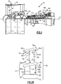
- the vane arc segment 60 is supported in the engine 20 by a structural spar piece 74, which is also shown in isolated views in Figures 3A and 3B.
- Figure 3A is a pressure side view and Figure 3B is a suction side view.
- the spar piece 74 is formed of a metallic alloy, such as but not limited to a single crystal nickel alloy.
- the spar piece 74 is comprised of a first spar platform 76a and first and second hollow legs 78/80. Although not shown, the spar platform 76a may have attachment features for supporting the spar piece 74 via an engine case or other fixed engine structure.
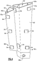
- the hollow legs 78/80 are also shown in an isolated view in Figure 4 , without the first platform 76a.
- each hollow leg 78/80 is cantilevered off of the first spar platform 76a and has a proximal end 82a at the spar platform 76a and an opposed distal end 82b. As will be discussed further below, the hollow legs 78/80 extend into the respective internal cavities 72 of the hollow ceramic airfoil section 62.
- the walls of the legs 78/80 define first and second sides 83a/83b and an adjoining third side 83c. Inside of the airfoil 68, the first side 83a faces toward the pressure side 68c of the airfoil 68, the second side faces toward the suction side 68d of the airfoil 68, and the third side faces toward the rib 70a.
- the walls of the legs 78/80 also encompass internal spar cavities 83 ( Figure 4 ), one or more of which may be subdivided by internal spar ribs. Such spar ribs may serve to stiffen the leg or legs 78/80 and carry bending and/or torsional loads.
- cooling air such as bleed air from the compressor section 24, may be provided through the cavities 83 to a downstream destination that is to be cooled.
- the downstream destination may be, but is not limited to, a turbine blade or a tangential on board injector (TOBI).
- each hollow leg 78/80 have raised bearing pads 84 that project therefrom.
- the bearing pads 84 are substantially rectangular, although other polygonal or rounded geometries may alternatively be used.
- the raised bearing pads 84 are integral to the walls of the legs 78/80.
- the raised bearing pads 84 may be formed by casting, machining, or combinations thereof, for example.
- multiple ones of the raised bearing pads 84 contact the walls 70 of the hollow ceramic airfoil section 62 and thereby support the hollow ceramic airfoil section 62 from within.
- Figure 5 depicts a representative example in which the raised bearing pad 84 is in areal contact with the wall 70.
- the term "areal contact” or variations thereof refers to contact between substantially the entire outward face of the raised bearing pad 84 and the wall 70.
- the outward face of each bearing pad 84 is contoured to match the localized contour of the wall 70 at the location of the bearing pad 84.
- each of the legs 78/80 has relatively few of the raised bearing pads 84 in comparison to other types of functional projections such as stand-offs that are used on baffles.
- each of the legs 78/80 includes a first group of the pads 84 at the proximal end 82a, a second group of the pads 84 at the distal end 82b, and a third group of the pads 84 intermediate the ends 82a/82b.
- a "group" of pads 84 are pads that lie in a common span range.
- the groups are spaced relatively far apart.
- the groups are spaced apart so as to maximize the wheelbase between adjacent groups while minimizing encroachment on other nearby design features.
- the legs 78/80 exclude the third group such that the first and second groups at the end 82a/82b are the only pads 84.
- the spar piece 74 further includes a second spar platform 76b that is secured directly to the distal end 82b of at least one of the hollow legs 78/80.
- one or both of the hollow legs 78/80 includes a lock orifice 86a and a lock pin 86b ( Figure 2B ) disposed through the lock orifice 86a.
- the lock pin 86b is of sufficient size such that it prevents the hollow leg 78 or 80 from being retracted through the internal cavity 72, thereby locking the spar piece 74 and hollow ceramic airfoil section 62 together.
- That leg 78/80 may be shorter such that it extends only a portion of the span of the cavity 72 of the airfoil 68.
- the shorter leg may also facilitate a reduction in thermal stress between the spar piece 74 and the ceramic airfoil 68.
- the other leg 78 may also have a lock orifice 86a for receiving a second lock pin.
- both legs 78/80 may have the lock orifices 86a and lock pins 86b to handle higher radial loads and/or moment force on the spar piece 74.
- support schemes for mounting vane segments formed of ceramic matrix composites are challenging due to lower material stress limits in comparison to high strength superalloys used for some traditional vane segments.
- traditional support schemes that utilize hooks or a series of rails can concentrate stresses, create aerodynamic loads, and/or create thermal stresses which may exceed material limits of ceramic matrix composites. Therefore, even though ceramic matrix composites may have many potential benefits, such benefits cannot be realized without a suitable support scheme.
- the legs 78/80 with the raised bearing pads 84 serve as support features to facilitate a low-stress mounting scheme from the inside of the airfoil 68, as opposed to an attachment scheme at the radial ends of the airfoil.
- combustion gases flow across the airfoil 68 and platforms 64/66.
- the flow causes aerodynamic loads, which are transmitted through the spar piece 74 to engine support structure(s).
- the raised bearing pads 84 are located at high load locations at which the airfoil 68 experiences maximum loads under the Durability or Structures Design Point (DDP & SDP, respectively).
- DDP & SDP Durability or Structures Design Point
- Such locations may be determined experimentally or by computer simulation.
- the locations are those at which the airfoil 68 experiences peak twist or bending deflection.
- Such locations may also be adjusted during a design phase by changing the location, angle, and/or presence of ribs.
- one or more of the raised bearing pads 84 may not be in contact with the walls 70 of the airfoil 68 when in a cold, non-operating condition.
- deflection of the airfoil 68 causes contact between two or more of the raised bearing pads 84 and the walls 70. In general, such deflection may be in an aft direction and radially outward direction. Therefore, raised bearing pads 84 that are on forward portions of the legs 78/80 may not be in contact with the walls 70, while raised bearing pads 84 that are on aft portions of the legs 78/80 may be in contact with the walls 70, such as the rib 70a.
Landscapes
- Engineering & Computer Science (AREA)
- Mechanical Engineering (AREA)
- General Engineering & Computer Science (AREA)
- Chemical & Material Sciences (AREA)
- Ceramic Engineering (AREA)
- Materials Engineering (AREA)
- Physics & Mathematics (AREA)
- Fluid Mechanics (AREA)
- Architecture (AREA)
- Turbine Rotor Nozzle Sealing (AREA)
Applications Claiming Priority (1)
| Application Number | Priority Date | Filing Date | Title |
|---|---|---|---|
| US17/086,893 US11448075B2 (en) | 2020-11-02 | 2020-11-02 | CMC vane arc segment with cantilevered spar |
Publications (1)
| Publication Number | Publication Date |
|---|---|
| EP4001592A1 true EP4001592A1 (de) | 2022-05-25 |
Family
ID=78414564
Family Applications (1)
| Application Number | Title | Priority Date | Filing Date |
|---|---|---|---|
| EP21205653.5A Pending EP4001592A1 (de) | 2020-11-02 | 2021-10-29 | Cmc-schaufelbogensegment mit freitragendem holm |
Country Status (2)
| Country | Link |
|---|---|
| US (1) | US11448075B2 (de) |
| EP (1) | EP4001592A1 (de) |
Cited By (2)
| Publication number | Priority date | Publication date | Assignee | Title |
|---|---|---|---|---|
| FR3136812A1 (fr) * | 2022-06-21 | 2023-12-22 | Safran Aircraft Engines | Roue de turbine a pale en cmc et mat structural en n-uplet |
| FR3136811A1 (fr) * | 2022-06-21 | 2023-12-22 | Safran Aircraft Engines | Roue de turbine a pale en cmc et mat structural maintenu par goupille |
Families Citing this family (4)
| Publication number | Priority date | Publication date | Assignee | Title |
|---|---|---|---|---|
| US11603765B1 (en) * | 2021-07-16 | 2023-03-14 | Raytheon Technologies Corporation | Airfoil assembly with fiber-reinforced composite rings and toothed exit slot |
| CN115638134B (zh) * | 2021-07-20 | 2025-08-08 | 中国航发商用航空发动机有限责任公司 | 导流静子及包含其的涡扇发动机 |
| US12000306B2 (en) * | 2022-06-03 | 2024-06-04 | Rtx Corporation | Vane arc segment with single-sided platforms |
| DE102024204952A1 (de) * | 2024-05-28 | 2025-12-04 | Siemens Energy Global GmbH & Co. KG | Leitschaufel |
Citations (4)
| Publication number | Priority date | Publication date | Assignee | Title |
|---|---|---|---|---|
| US20100068034A1 (en) * | 2008-09-18 | 2010-03-18 | Schiavo Anthony L | CMC Vane Assembly Apparatus and Method |
| US20190153879A1 (en) * | 2017-11-20 | 2019-05-23 | Rolls-Royce Corporation | Airfoil for a gas turbine engine having insulating materials |
| US20190368360A1 (en) * | 2018-06-01 | 2019-12-05 | Rolls-Royce North American Technologies Inc. | Turbine vane assembly with ceramic matrix composite components |
| EP3670842A1 (de) * | 2018-12-20 | 2020-06-24 | Rolls-Royce plc | Gleitende schaufelanordnung aus keramischem faserverbundwerkstoff für gasturbinentriebwerke |
Family Cites Families (9)
| Publication number | Priority date | Publication date | Assignee | Title |
|---|---|---|---|---|
| US3301527A (en) * | 1965-05-03 | 1967-01-31 | Gen Electric | Turbine diaphragm structure |
| US6224339B1 (en) * | 1998-07-08 | 2001-05-01 | Allison Advanced Development Company | High temperature airfoil |
| US6283708B1 (en) * | 1999-12-03 | 2001-09-04 | United Technologies Corporation | Coolable vane or blade for a turbomachine |
| US8142137B2 (en) * | 2008-11-26 | 2012-03-27 | Alstom Technology Ltd | Cooled gas turbine vane assembly |
| US10309240B2 (en) | 2015-07-24 | 2019-06-04 | General Electric Company | Method and system for interfacing a ceramic matrix composite component to a metallic component |
| US10612385B2 (en) * | 2016-03-07 | 2020-04-07 | Rolls-Royce Corporation | Turbine blade with heat shield |
| US10808560B2 (en) * | 2018-06-20 | 2020-10-20 | Rolls-Royce Corporation | Turbine vane assembly with ceramic matrix composite components |
| US10774665B2 (en) | 2018-07-31 | 2020-09-15 | General Electric Company | Vertically oriented seal system for gas turbine vanes |
| US10883371B1 (en) * | 2019-06-21 | 2021-01-05 | Rolls-Royce Plc | Ceramic matrix composite vane with trailing edge radial cooling |
-
2020
- 2020-11-02 US US17/086,893 patent/US11448075B2/en active Active
-
2021
- 2021-10-29 EP EP21205653.5A patent/EP4001592A1/de active Pending
Patent Citations (4)
| Publication number | Priority date | Publication date | Assignee | Title |
|---|---|---|---|---|
| US20100068034A1 (en) * | 2008-09-18 | 2010-03-18 | Schiavo Anthony L | CMC Vane Assembly Apparatus and Method |
| US20190153879A1 (en) * | 2017-11-20 | 2019-05-23 | Rolls-Royce Corporation | Airfoil for a gas turbine engine having insulating materials |
| US20190368360A1 (en) * | 2018-06-01 | 2019-12-05 | Rolls-Royce North American Technologies Inc. | Turbine vane assembly with ceramic matrix composite components |
| EP3670842A1 (de) * | 2018-12-20 | 2020-06-24 | Rolls-Royce plc | Gleitende schaufelanordnung aus keramischem faserverbundwerkstoff für gasturbinentriebwerke |
Cited By (2)
| Publication number | Priority date | Publication date | Assignee | Title |
|---|---|---|---|---|
| FR3136812A1 (fr) * | 2022-06-21 | 2023-12-22 | Safran Aircraft Engines | Roue de turbine a pale en cmc et mat structural en n-uplet |
| FR3136811A1 (fr) * | 2022-06-21 | 2023-12-22 | Safran Aircraft Engines | Roue de turbine a pale en cmc et mat structural maintenu par goupille |
Also Published As
| Publication number | Publication date |
|---|---|
| US20220136393A1 (en) | 2022-05-05 |
| US11448075B2 (en) | 2022-09-20 |
Similar Documents
| Publication | Publication Date | Title |
|---|---|---|
| US11448075B2 (en) | CMC vane arc segment with cantilevered spar | |
| US11035243B2 (en) | Seal assembly for gas turbine engines | |
| EP3892822B1 (de) | Leitschaufelträgersystem | |
| US12025020B2 (en) | Vane system with continuous support ring | |
| US11242762B2 (en) | Vane with collar | |
| EP4015771B1 (de) | Schaufelbogensegment mit wärmeisolationselement | |
| EP3974617B1 (de) | Keramische gasturbinenschaufel mit in 3 zonen mit jeweils unterschiedlichem abstand angeordneten filmkühlungsbohrungen | |
| EP3825519A1 (de) | Schaufel mit kragen | |
| EP4253726B1 (de) | Cmc-schaufelverbindungs-flansche mit durch schichten verlaufenden dichtungsschlitzen | |
| EP4030035B1 (de) | Leitschaufelsegment mit stiftbefestigung und verdrehsicherungs-stabilisierungsstab | |
| EP4080017B1 (de) | Schaufelanordnung mit integriertem düsenrohr | |
| EP4086433B1 (de) | Dichtungsanordnung mit dichtungsbogensegment | |
| EP3865669B1 (de) | Schaufelbogenabschnittplattformflansch eines gasturbinentriebwerks mit kappe | |
| EP4033071B1 (de) | Schaufel mit stiftbefestigung und verdrehsicherung | |
| US12523157B2 (en) | Ceramic vane ring-strut-ring attachment configuration | |
| US12258881B2 (en) | Turbine section with ceramic support rings and ceramic vane arc segments | |
| US12241387B1 (en) | Tilted CMC vane arc segment | |
| US11708765B1 (en) | Gas turbine engine article with branched flange | |
| US11668199B2 (en) | Vane arc segment with radially projecting flanges | |
| EP3808940B1 (de) | Cmc-schaufel für ein gasturbinentriebwerk mit kühllöchern |
Legal Events
| Date | Code | Title | Description |
|---|---|---|---|
| PUAI | Public reference made under article 153(3) epc to a published international application that has entered the european phase |
Free format text: ORIGINAL CODE: 0009012 |
|
| STAA | Information on the status of an ep patent application or granted ep patent |
Free format text: STATUS: THE APPLICATION HAS BEEN PUBLISHED |
|
| AK | Designated contracting states |
Kind code of ref document: A1 Designated state(s): AL AT BE BG CH CY CZ DE DK EE ES FI FR GB GR HR HU IE IS IT LI LT LU LV MC MK MT NL NO PL PT RO RS SE SI SK SM TR |
|
| STAA | Information on the status of an ep patent application or granted ep patent |
Free format text: STATUS: REQUEST FOR EXAMINATION WAS MADE |
|
| 17P | Request for examination filed |
Effective date: 20221125 |
|
| RBV | Designated contracting states (corrected) |
Designated state(s): AL AT BE BG CH CY CZ DE DK EE ES FI FR GB GR HR HU IE IS IT LI LT LU LV MC MK MT NL NO PL PT RO RS SE SI SK SM TR |
|
| RAP3 | Party data changed (applicant data changed or rights of an application transferred) |
Owner name: RTX CORPORATION |
|
| GRAP | Despatch of communication of intention to grant a patent |
Free format text: ORIGINAL CODE: EPIDOSNIGR1 |
|
| STAA | Information on the status of an ep patent application or granted ep patent |
Free format text: STATUS: GRANT OF PATENT IS INTENDED |