EP4001611B1 - Agencement de piston pour un moteur à combustion propre - Google Patents
Agencement de piston pour un moteur à combustion propre Download PDFInfo
- Publication number
- EP4001611B1 EP4001611B1 EP20207979.4A EP20207979A EP4001611B1 EP 4001611 B1 EP4001611 B1 EP 4001611B1 EP 20207979 A EP20207979 A EP 20207979A EP 4001611 B1 EP4001611 B1 EP 4001611B1
- Authority
- EP
- European Patent Office
- Prior art keywords
- piston
- water
- combustion engine
- compartment
- sealing ring
- Prior art date
- Legal status (The legal status is an assumption and is not a legal conclusion. Google has not performed a legal analysis and makes no representation as to the accuracy of the status listed.)
- Active
Links
Images


Classifications
-
- F—MECHANICAL ENGINEERING; LIGHTING; HEATING; WEAPONS; BLASTING
- F02—COMBUSTION ENGINES; HOT-GAS OR COMBUSTION-PRODUCT ENGINE PLANTS
- F02F—CYLINDERS, PISTONS OR CASINGS, FOR COMBUSTION ENGINES; ARRANGEMENTS OF SEALINGS IN COMBUSTION ENGINES
- F02F3/00—Pistons
- F02F3/0015—Multi-part pistons
-
- F—MECHANICAL ENGINEERING; LIGHTING; HEATING; WEAPONS; BLASTING
- F02—COMBUSTION ENGINES; HOT-GAS OR COMBUSTION-PRODUCT ENGINE PLANTS
- F02B—INTERNAL-COMBUSTION PISTON ENGINES; COMBUSTION ENGINES IN GENERAL
- F02B43/00—Engines characterised by operating on gaseous fuels; Plants including such engines
- F02B43/10—Engines or plants characterised by use of other specific gases, e.g. acetylene, oxyhydrogen
-
- F—MECHANICAL ENGINEERING; LIGHTING; HEATING; WEAPONS; BLASTING
- F02—COMBUSTION ENGINES; HOT-GAS OR COMBUSTION-PRODUCT ENGINE PLANTS
- F02F—CYLINDERS, PISTONS OR CASINGS, FOR COMBUSTION ENGINES; ARRANGEMENTS OF SEALINGS IN COMBUSTION ENGINES
- F02F3/00—Pistons
- F02F3/28—Other pistons with specially-shaped head
-
- F—MECHANICAL ENGINEERING; LIGHTING; HEATING; WEAPONS; BLASTING
- F01—MACHINES OR ENGINES IN GENERAL; ENGINE PLANTS IN GENERAL; STEAM ENGINES
- F01B—MACHINES OR ENGINES, IN GENERAL OR OF POSITIVE-DISPLACEMENT TYPE, e.g. STEAM ENGINES
- F01B7/00—Machines or engines with two or more pistons reciprocating within same cylinder or within essentially coaxial cylinders
-
- F—MECHANICAL ENGINEERING; LIGHTING; HEATING; WEAPONS; BLASTING
- F01—MACHINES OR ENGINES IN GENERAL; ENGINE PLANTS IN GENERAL; STEAM ENGINES
- F01M—LUBRICATING OF MACHINES OR ENGINES IN GENERAL; LUBRICATING INTERNAL COMBUSTION ENGINES; CRANKCASE VENTILATING
- F01M1/00—Pressure lubrication
- F01M1/02—Pressure lubrication using lubricating pumps
-
- F—MECHANICAL ENGINEERING; LIGHTING; HEATING; WEAPONS; BLASTING
- F01—MACHINES OR ENGINES IN GENERAL; ENGINE PLANTS IN GENERAL; STEAM ENGINES
- F01M—LUBRICATING OF MACHINES OR ENGINES IN GENERAL; LUBRICATING INTERNAL COMBUSTION ENGINES; CRANKCASE VENTILATING
- F01M1/00—Pressure lubrication
- F01M1/16—Controlling lubricant pressure or quantity
-
- F—MECHANICAL ENGINEERING; LIGHTING; HEATING; WEAPONS; BLASTING
- F01—MACHINES OR ENGINES IN GENERAL; ENGINE PLANTS IN GENERAL; STEAM ENGINES
- F01M—LUBRICATING OF MACHINES OR ENGINES IN GENERAL; LUBRICATING INTERNAL COMBUSTION ENGINES; CRANKCASE VENTILATING
- F01M11/00—Component parts, details or accessories, not provided for in, or of interest apart from, groups F01M1/00 - F01M9/00
- F01M11/02—Arrangements of lubricant conduits
-
- F—MECHANICAL ENGINEERING; LIGHTING; HEATING; WEAPONS; BLASTING
- F01—MACHINES OR ENGINES IN GENERAL; ENGINE PLANTS IN GENERAL; STEAM ENGINES
- F01M—LUBRICATING OF MACHINES OR ENGINES IN GENERAL; LUBRICATING INTERNAL COMBUSTION ENGINES; CRANKCASE VENTILATING
- F01M9/00—Lubrication means having pertinent characteristics not provided for in, or of interest apart from, groups F01M1/00 - F01M7/00
-
- F—MECHANICAL ENGINEERING; LIGHTING; HEATING; WEAPONS; BLASTING
- F01—MACHINES OR ENGINES IN GENERAL; ENGINE PLANTS IN GENERAL; STEAM ENGINES
- F01N—GAS-FLOW SILENCERS OR EXHAUST APPARATUS FOR MACHINES OR ENGINES IN GENERAL; GAS-FLOW SILENCERS OR EXHAUST APPARATUS FOR INTERNAL-COMBUSTION ENGINES
- F01N3/00—Exhaust or silencing apparatus having means for purifying, rendering innocuous, or otherwise treating exhaust
- F01N3/005—Exhaust or silencing apparatus having means for purifying, rendering innocuous, or otherwise treating exhaust for draining or otherwise eliminating condensates or moisture accumulating in the apparatus
-
- F—MECHANICAL ENGINEERING; LIGHTING; HEATING; WEAPONS; BLASTING
- F02—COMBUSTION ENGINES; HOT-GAS OR COMBUSTION-PRODUCT ENGINE PLANTS
- F02B—INTERNAL-COMBUSTION PISTON ENGINES; COMBUSTION ENGINES IN GENERAL
- F02B75/00—Other engines
- F02B75/28—Engines with two or more pistons reciprocating within same cylinder or within essentially coaxial cylinders
-
- F—MECHANICAL ENGINEERING; LIGHTING; HEATING; WEAPONS; BLASTING
- F02—COMBUSTION ENGINES; HOT-GAS OR COMBUSTION-PRODUCT ENGINE PLANTS
- F02B—INTERNAL-COMBUSTION PISTON ENGINES; COMBUSTION ENGINES IN GENERAL
- F02B77/00—Component parts, details or accessories, not otherwise provided for
- F02B77/04—Cleaning of, preventing corrosion or erosion in, or preventing unwanted deposits in, combustion engines
-
- F—MECHANICAL ENGINEERING; LIGHTING; HEATING; WEAPONS; BLASTING
- F02—COMBUSTION ENGINES; HOT-GAS OR COMBUSTION-PRODUCT ENGINE PLANTS
- F02M—SUPPLYING COMBUSTION ENGINES IN GENERAL WITH COMBUSTIBLE MIXTURES OR CONSTITUENTS THEREOF
- F02M21/00—Apparatus for supplying engines with non-liquid fuels, e.g. gaseous fuels stored in liquid form
- F02M21/02—Apparatus for supplying engines with non-liquid fuels, e.g. gaseous fuels stored in liquid form for gaseous fuels
- F02M21/0203—Apparatus for supplying engines with non-liquid fuels, e.g. gaseous fuels stored in liquid form for gaseous fuels characterised by the type of gaseous fuel
- F02M21/0209—Hydrocarbon fuels, e.g. methane or acetylene
-
- F—MECHANICAL ENGINEERING; LIGHTING; HEATING; WEAPONS; BLASTING
- F16—ENGINEERING ELEMENTS AND UNITS; GENERAL MEASURES FOR PRODUCING AND MAINTAINING EFFECTIVE FUNCTIONING OF MACHINES OR INSTALLATIONS; THERMAL INSULATION IN GENERAL
- F16J—PISTONS; CYLINDERS; SEALINGS
- F16J1/00—Pistons; Trunk pistons; Plungers
- F16J1/08—Constructional features providing for lubrication
-
- F—MECHANICAL ENGINEERING; LIGHTING; HEATING; WEAPONS; BLASTING
- F16—ENGINEERING ELEMENTS AND UNITS; GENERAL MEASURES FOR PRODUCING AND MAINTAINING EFFECTIVE FUNCTIONING OF MACHINES OR INSTALLATIONS; THERMAL INSULATION IN GENERAL
- F16J—PISTONS; CYLINDERS; SEALINGS
- F16J9/00—Piston-rings, e.g. non-metallic piston-rings, seats therefor; Ring sealings of similar construction
- F16J9/12—Details
-
- F—MECHANICAL ENGINEERING; LIGHTING; HEATING; WEAPONS; BLASTING
- F01—MACHINES OR ENGINES IN GENERAL; ENGINE PLANTS IN GENERAL; STEAM ENGINES
- F01M—LUBRICATING OF MACHINES OR ENGINES IN GENERAL; LUBRICATING INTERNAL COMBUSTION ENGINES; CRANKCASE VENTILATING
- F01M1/00—Pressure lubrication
- F01M1/02—Pressure lubrication using lubricating pumps
- F01M2001/0207—Pressure lubrication using lubricating pumps characterised by the type of pump
-
- F—MECHANICAL ENGINEERING; LIGHTING; HEATING; WEAPONS; BLASTING
- F02—COMBUSTION ENGINES; HOT-GAS OR COMBUSTION-PRODUCT ENGINE PLANTS
- F02B—INTERNAL-COMBUSTION PISTON ENGINES; COMBUSTION ENGINES IN GENERAL
- F02B43/00—Engines characterised by operating on gaseous fuels; Plants including such engines
- F02B43/10—Engines or plants characterised by use of other specific gases, e.g. acetylene, oxyhydrogen
- F02B2043/106—Hydrogen obtained by electrolysis
-
- Y—GENERAL TAGGING OF NEW TECHNOLOGICAL DEVELOPMENTS; GENERAL TAGGING OF CROSS-SECTIONAL TECHNOLOGIES SPANNING OVER SEVERAL SECTIONS OF THE IPC; TECHNICAL SUBJECTS COVERED BY FORMER USPC CROSS-REFERENCE ART COLLECTIONS [XRACs] AND DIGESTS
- Y02—TECHNOLOGIES OR APPLICATIONS FOR MITIGATION OR ADAPTATION AGAINST CLIMATE CHANGE
- Y02T—CLIMATE CHANGE MITIGATION TECHNOLOGIES RELATED TO TRANSPORTATION
- Y02T10/00—Road transport of goods or passengers
- Y02T10/10—Internal combustion engine [ICE] based vehicles
- Y02T10/30—Use of alternative fuels, e.g. biofuels
Definitions
- the present invention relates to a piston arrangement for a clean combustion engine, such as a hydrogen engine.
- the invention further relates to a clean combustion engine, such as a hydrogen engine, and a vehicle.
- the invention is applicable on vehicles, in particularly heavy vehicles, such as e.g. trucks.
- trucks such as e.g. trucks.
- the piston arrangement and clean combustion engine are also applicable for other type of vehicles, such as cars, industrial construction machines, wheel loaders, etc.
- a piston arrangement for a clean combustion engine such as a hydrogen engine
- the piston arrangement comprising:
- the piston is lubricated in the cylinder using only water as lubricant which is pressurized by the gas in the first compartment, the first compartment typically being the combustion chamber.
- the lubricating water is pressurized close to its point of application, avoiding excessive pressure losses otherwise occurring.
- sealing water is simpler to achieve compared to sealing gas.
- the clean combustion engine is arranged and configured to combust a hydrogen-based fuel producing water as by-product in the exhausts, wherein the piston arrangement is arranged to utilize the by-product water in the water channel to lubricate the sealing ring.
- the lubrication of the piston in the cylinder is self-contained in relation to the operation of the clean combustion engine, as the lubricating water is produced as a by-product during combustion, and is pressurized by the pressurized gas in the first compartment. In other words, no external addition of lubricant or the pressurization thereof is needed.
- the pumping element is prestressed and movably integrated in the piston head for compressing the water in the water channel.
- the pumping element comprises a first surface arranged and configured to receive a pressure from the pressurized gas inside the first compartment, and comprises a second surface opposite to the first surface, facing the water in the water channel.
- the pumping element can transfer the pressure acting on the first surface from the pressurized gas, to a compressing force of the water in the water channel via a pressure from the second surface.
- the pumping element comprises a disk-shaped element, or an element shaped as a cylinder, comprising the first and second surfaces.
- the water channel comprises a plurality of channel portions extending from the pumping element to an outer periphery of the piston.
- the channel portions may be arranged as separate channel legs extending from a center cavity of the water channel, the center cavity being subject to the pumping element and pressurization of the water.
- the channel portions, or channel legs are evenly distributed in the circumferential direction of the piston.
- the piston arrangement further comprises a water supply for supplying water to the water channel, and a check valve arranged internally of the piston downstream of the water supply.
- the check valve is arranged between the center cavity and the water supply.
- the check valve is arranged relatively close to the pressurisation of the lubricating water by the pumping element.
- the water supply may be arranged to supply water from a product stream downstream of the clean combustion engine, as will be described later.
- the water supply is originating from a condenser, e.g. comprised in an exhaust gas recirculation, EGR, system of the clean combustion engine.
- EGR exhaust gas recirculation
- the water channel comprises an outlet arranged and configured to discharge water into the second compartment.
- each channel leg comprises an outlet arranged and configured to discharge water into the second compartment.
- the pumping element is configured to pressurise the water to a corresponding pressure as the pressurized gas in the first compartment.
- the sealing ring separating the first compartment from the second compartment is pressure equalized, and does not need to handle any pressure differences.
- the pressure over the sealing ring is balanced, and may seal to the first compartment with a relatively low seal friction as compared to if the lubricating water would not be pressurised to correspond to the pressure of the pressurized gas in the first compartment (that is, the sealing ring is subject to the pressurized gas on one side, and the pressurized water on the other side).
- the pumping element is configured to pressurise the water to 80 % - 120 % of the pressure of the pressurized gas in the first compartment.
- the sealing ring is a first sealing ring and the sealing arrangement comprises a second sealing ring configured to be arranged to seal the piston to the cylinder wall and separating the second compartment from a third compartment.
- the first sealing ring is top seal
- the second sealing ring is a secondary seal arranged further from the first compartment compared to the top seal.
- the water channel has a main extension in a fluid flow direction, and a cross section perpendicular to the main extension enclosed of internal walls of the piston.
- the water in the water channel may be adequately pressurized and easily transported to the sealing arrangement.
- the piston arrangement is an oil-free piston arrangement.
- the first compartment may according to at least one example embodiment be the combustion chamber, wherein the combustion chamber is comprised in the cylinder above the head of the piston.
- the clean combustion engine is typically configured to compress the gaseous fuel, e.g. hydrogen or a hydrogen-based fuel, to achieve a compression ignition.
- the clean combustion engine may simply be referred to as an internal combustion engine.
- a clean combustion engine such as a hydrogen engine
- the clean combustion engine comprises a piston arrangement according to the first aspect of the invention, and a cylinder in which the piston is reciprocally arranged.
- the clean combustion engine is arranged and configured to combust a hydrogen-based fuel producing water as by-product in the exhausts, wherein the piston arrangement is arranged to utilize the by-product water in the water channel to lubricate the sealing ring.
- the water as by-product is used as lubricating water, and the lubrication of the piston in the cylinder is self-contained in relation to the operation of the clean combustion engine, as described in relation to the first aspect of the invention.
- the piston is a dual acting piston acting on a first side for combustion action, and a on a second side opposite to the first side, for compression action.
- Such dual acting piston is particularly advantageous for a clean combustion engine, and the water lubrication may be arranged space-efficiently.
- a vehicle comprising a clean combustion engine according to the second aspect of the invention is provided.
- the vehicle comprises a condenser arranged in downstream fluid communication with the clean combustion engine for receiving the exhausts, the condenser being configured to condense the exhausts to form a condensate of liquid water, wherein the liquid water is used in the water channel to lubricate the sealing ring.
- liquid water of the condensate which originally is a by-product of the combustion in the clean combustion engine, is used as lubricating water.
- the condenser may e.g. be comprised in an exhaust gas recirculation, EGR, system of the vehicle.
- a vehicle 1000 with an internal combustion engine 1100 there is provided a vehicle 1000 with an internal combustion engine 1100 according to the present invention.
- the vehicle 1000 depicted in Fig. 1 is a truck for which the inventive internal combustion engine 1100, which will be described in detail below, is particularly suitable for.
- the internal combustion engine 1100 may as well be implemented in other types of vehicles, such as in busses, light-weight trucks, passenger cars, marine applications etc.
- the internal combustion engine 1100 is here a clean combustion engine 1100 or clean engine 1100, and is operated on a gaseous fuel such as e.g. hydrogen, and may thus be referred to as a hydrogen or H2 engine.
- Fig. 2 discloses a piston arrangement 1 which may be used in the clean combustion engine 1100 of Fig. 1 .
- the piston arrangement 1 comprises a piston 10 and a cylinder 50 having a cylinder wall 52 defining a cylinder space in which the piston 10 is arranged to move reciprocally.
- the piston comprises a piston head 12 having a top surface 13 arranged and configured to face a first compartment 70 with pressurized gas, typically a combustion chamber in which gaseous fuel is combusted.
- pressurized gas typically a combustion chamber in which gaseous fuel is combusted.
- the first compartment 70 is delimited of the cylinder wall 50 and the top surface 13 of the piston head 12.
- the piston arrangement 1 further comprises a sealing arrangement 20 including a first sealing ring 22 and a second sealing ring 24, both arranged to seal the piston 10 to the cylinder wall 52 such that the first sealing ring 22 separates the first compartment 70 from a second compartment 72, and the second sealing ring 24 separates the second compartment 72 from a third compartment 74.
- the first sealing ring 22 may thus act as a top seal 22, and the second sealing ring 24 as a secondary seal 24 or lower seal 24.
- the piston arrangement 1 is configured to supply liquid to the sealing arrangement 20.
- the liquid is here water, and the piston arrangement 1 is thus configured to supply water to the sealing arrangement 20.
- the piston arrangement 1 comprises a water channel 14 extending from an interior of the piston 10 to at least the first sealing ring 22 to provide water for lubricating the sealing arrangement 20 and the first sealing ring 22.
- the water channel 14 comprises an outlet 15 arranged and configured to discharge water into the second compartment 72.
- the piston 10 further comprises pumping element 30 arranged and configured to pressurize the water in the water channel 14 by pressurised gas in the first compartment 70.
- the pumping element 30 is arranged centrally in an end portion of the piston head 12, the pumping element 30 having a first surface being arranged as a top surface portion 32 forming at least a part of the top surface 13 of the piston head 12, and having a second surface opposite to the first surface, the second surface being arranged as a bottom surface portion 33 facing the water channel 14.
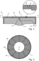
- the pumping element 30 is prestressed by means of at least one spring element, here springs 34, or flow springs 34, shown in the enlarged part of Fig. 3
- the pumping element 30 is movably integrated in the piston head 12 for compressing the water in the water channel 14. That is, the pumping element 30 may be moved within the limits of the springs 34, and the internal walls of the piston head 12 delimiting the movement of the pumping element 30.
- the pumping element 30 operates as follows.
- the pressurized gas in the first compartment 70 acts on the top surface portion 32, whereby the prestressed and movably arranged pumping element 30 in response acts on the water in the water channel 14 via the bottom surface portion 33.
- the pumping element 30 can transfer the pressure acting on the top surface portion 32 from the pressurized gas, to a compressing force of the water in the water channel 14 via a pressure from the bottom surface portion 33.
- the pumping element 30 may be configured to pressurise the water in the water channel e.g.
- the pressure over the first sealing ring 22 is balanced, and may seal to the first compartment 70 with a relatively low seal friction, that is, the first sealing ring 22, here being a top seal 22, is subject to gas pressure of the pressurized gas on a first side (top side), and is subject to the pressurized water on an opposite, second side (bottom side).
- the second sealing ring 24, and any further sealing ring arranged adjacent to the second sealing ring deals with the pressure difference to the surroundings.
- Fig. 4 is a cross section along line A-A of the piston head 12 of Fig. 3 , showing the water channel 14 comprising a plurality of channel portions (of which only some 14A, 14B, 14C are indicated) shaped as channel legs extending from a centre channel chamber 16 or centre cavity 16 arranged below the pumping element 30, to an outer periphery 11 of the piston 10, and the sealing arrangement 20 (as shown in Fig. 2 ).
- the water channel 14 comprises ten channel portions evenly distributed circumferentially along the piston head 12. It should be noted that the number of channel portions are exemplifying. It should be realized that there may be more channel portions water channel 14, but also fewer.
- the water channel 14 is thus arranged internally of the piston 10 or piston head 12, and comprises the centre cavity 16, extending from a water supply 18 to a respective outlet of the channel portions 14A, 14B, 14C.
- the water channel 14 may be referred to as a water tube 14, or liquid pipe 14.
- the water channel 14 is enclosed of internal walls of the piston 10 or piston head 12, and thus has a cross section perpendicular to a main extension which is delimited of the internal walls of the piston 10 or piston head 12.
- the main extension of the water channel 14 is typically extending in the same direction as the fluid flow direction of the water.
- the water to the water channel 14 is provided by a water supply 18, here schematically indicated outside of the piston 10, for supplying water to the water channel 14 via a first channel part 17 (as seen in Fig. 2 , via conduits 18A).
- the piston head 12 further comprises a check valve 19 arranged internally of the piston head 12 and being configured to prevent reverse flow in the first channel part 17 of the water channel 14, downstream of the water supply 18.
- the water channel 14 can be divided into at least three parts, the first channel part 17 arranged downstream of the water supply 18 and regulated by the check valve 19, a second channel part being the centre channel chamber 16 or centre cavity 16 which is arranged such that the water therein is in contact with the bottom surface portion 33 of the pumping element 30 for pressurising the water, and a third channel part comprising one or more of the channel portions 14A, 14B, 14C with a respective outlet.
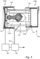
- Fig. 5 is showing an example embodiment of the invention being at least a part of an internal combustion engine 100, here a clean combustion engine 100 in the form of a hydrogen engine, or H2-engine 100, which may replace the clean combustion engine 1100 described with reference to Fig. 1 .
- the internal combustion engine 100 comprises a first side 100A for combustion action, and a second side 100B opposite the first side 100A, for compression action.
- Each one of the first and second sides 100A, 100B comprises a piston arrangement 101, 101' and a cylinder 150, 150' corresponding to the piston arrangement 1 and cylinder 50 of Figs. 2-4 , respectively, which features and functions are not repeated here again.
- the piston 110 is a dual acting piston with a first piston portion 110A operating on the first side 100A, and a second piston portion 110B operating on the second side 100B, for reciprocal motion in the respective cylinder 150, 150'. It should be noted that only one dual piston arranged for reciprocal motion in the cylinders 150, 150' is shown in Fig. 5 , but that the internal combustion engine 100 may comprise further such configurations.
- the clean combustion engine 100 comprises post combustion component(s) 160 comprising e.g. a secondary expander and a piston compressor (e.g. combined into one duo piston), and/or a heat exchanger (although not shown) arranged downstream of, and in fluid communication with the first side 100A (being a combustion side) for receiving exhaust gas from a combustion chamber.
- post combustion component(s) 160 is only schematically indicated in Fig. 5 as being arranged downstream of the first side 100A.
- the heat exchanger may e.g. house a three-way catalytic converter. The heat exchanger and the three-way catalytic converter are operated known to those skilled in the art.
- the clean combustion engine 100 of Fig. 5 further comprises a condenser 162 arranged in downstream fluid communication with the post combustion component(s) 160 for receiving exhaust gas, the condenser 162 is configured to condense the exhaust gas to form a condensate of liquid water.
- the condenser 162 is only shown schematically in Fig. 5 .
- the condensate of liquid water may be used as the lubricating water in the water channel 14 as previously described, by utilizing a first conduit 164 configured to feed the respective sealing arrangement of the piston arrangements 101, 101'.
- other ways of supplying the lubricating water to the clean combustion engine 100 e.g. not using the condenser 162, is within the scope of the invention.
- a condenser 262 and a water conduit 264 for supplying liquid water of the condensate to the clean combustion engine 1100 is shown without the disclosure of a dual-acting piston as shown in Fig. 5 .
- the clean combustion engine 1100 is arranged and configured to combust a hydrogen-based fuel producing water as by-product in the exhausts, wherein the piston arrangement in the clean combustion engine 1100 is arranged to utilize the by-product water in the water channel to lubricate the sealing arrangement (as shown in Figs. 2-4 ), by means of the condenser 262 and water conduit 264.
- the water supply to the water channel 14 of Figs. 2-4 may comprise the condenser 262.
- cylinder 50, 150, 150' may be considered as being a part of the piston arrangement 1, 101, 101', or may be considered to be external the piston arrangement 1, 101, 101' e.g. as a portion of an engine block housing.
Landscapes
- Engineering & Computer Science (AREA)
- General Engineering & Computer Science (AREA)
- Mechanical Engineering (AREA)
- Chemical & Material Sciences (AREA)
- Combustion & Propulsion (AREA)
- Chemical Kinetics & Catalysis (AREA)
- General Chemical & Material Sciences (AREA)
- Oil, Petroleum & Natural Gas (AREA)
- Output Control And Ontrol Of Special Type Engine (AREA)
Claims (15)
- Agencement de piston (1) pour moteur à combustion propre (100), tel qu'un moteur à hydrogène, comprenant :- un piston (10) configuré pour exécuter un mouvement alternatif à l'intérieur d'un cylindre (50) doté d'une paroi de cylindre (52), le piston comportant une tête de cylindre (12) configurée pour être en face d'un premier compartiment (70) contenant du gaz pressurisé,- un agencement d'étanchéité (20) comprenant au moins une bague d'étanchéité (22) configurée pour être disposée de manière à sceller le piston sur la paroi de cylindre et séparant le premier compartiment d'un deuxième compartiment (72), caractérisé par- un canal à eau (14) s'étendant depuis un intérieur du piston jusqu'à la bague d'étanchéité pour fournir de l'eau afin de lubrifier la bague d'étanchéité,la tête de piston comprenant un élément de pompage (30) configuré pour être disposé de manière à pressuriser l'eau dans le canal à eau à l'aide de gaz pressurisé dans le premier compartiment.
- Agencement de piston selon la revendication 1, le moteur à combustion propre est disposé et configuré pour brûler un carburant à base d'hydrogène produisant de l'eau en tant que produit secondaire dans les échappements, l'agencement de piston étant conçu pour utiliser l'eau en tant que produit secondaire dans le canal à eau afin de lubrifier la bague d'étanchéité.
- Agencement de piston selon l'une quelconque des revendications 1 à 2, dans lequel l'élément de pompage est précontraint et intégré de manière mobile dans la tête de piston pour comprimer l'eau dans le canal à eau.
- Agencement de piston selon l'une quelconque des revendications précédentes, dans lequel le canal à eau comprend une pluralité de sections de canal (14A, 14B, 14C) s'étendant depuis l'élément de pompage jusqu'à une périphérie extérieure (11) du piston.
- Agencement de piston selon l'une quelconque des revendications précédentes, comprenant en outre une alimentation en eau (18) pour fournir de l'eau au canal à eau, et une vanne de contrôle (19) disposée à l'intérieur du piston en aval de l'alimentation en eau.
- Agencement de piston selon l'une quelconque des revendications précédentes, dans lequel le canal à eau comprend une sortie (15) disposée et configurée pour décharger de l'eau dans le deuxième compartiment.
- Agencement de piston selon l'une quelconque des revendications précédentes, dans lequel l'élément de pompage est configuré pour pressuriser l'eau jusqu'à une pression correspondante à celle du gaz pressurisé dans le premier compartiment.
- Agencement de piston selon l'une quelconque des revendications précédentes, dans lequel la bague d'étanchéité est une première bague d'étanchéité (22) et l'agencement d'étanchéité comprend une seconde bague d'étanchéité (24) configurée pour être disposée de manière à sceller le piston sur la paroi de cylindre et à séparer le deuxième compartiment d'un troisième compartiment (74).
- Agencement de piston selon l'une quelconque des revendications précédentes, dans lequel le canal à eau a une extension principale dans le sens d'écoulement du fluide, et une section transversale perpendiculaire à l'extension principale circonscrite par des parois internes du piston.
- Agencement de piston selon l'une quelconque des revendications précédentes, qui est un agencement de piston sans huile.
- Moteur à combustion propre (100, 1100), tel qu'un moteur à hydrogène, comprenant un agencement de piston selon les revendications 1 à 10, et un cylindre dans lequel le piston est disposé en va-et-vient.
- Moteur à combustion propre selon la revendication 11, le moteur à combustion propre est disposé et configuré pour brûler un carburant à base d'hydrogène produisant de l'eau en tant que produit secondaire dans les échappements, l'agencement de piston étant conçu pour utiliser l'eau en tant que produit secondaire dans le canal à eau afin de lubrifier la bague d'étanchéité.
- Moteur à combustion propre selon l'une quelconque des revendications 11 à 12, dans lequel le piston est un piston à double action (110) agissant sur un premier côté (100A) pour une action de combustion et sur un second côté (100B) opposé au premier côté pour une action de compression.
- Véhicule (1000) comprenant un moteur à combustion propre (1100, 100) selon l'une quelconque des revendications 11 à 13.
- Véhicule selon la revendication 14, comprenant en outre un condensateur (162, 262) disposé en communication fluidique aval avec le moteur à combustion propre pour recevoir les échappements, le condensateur étant configuré pour condenser les échappements afin de former un condensé d'eau liquide, l'eau liquide étant utilisée dans le canal à eau pour lubrifier la bague d'étanchéité.
Priority Applications (3)
| Application Number | Priority Date | Filing Date | Title |
|---|---|---|---|
| EP20207979.4A EP4001611B1 (fr) | 2020-11-17 | 2020-11-17 | Agencement de piston pour un moteur à combustion propre |
| US17/454,144 US11459978B2 (en) | 2020-11-17 | 2021-11-09 | Piston arrangement for a clean combustion engine |
| CN202111346402.3A CN114508442B (zh) | 2020-11-17 | 2021-11-15 | 用于清洁燃烧发动机的活塞装置 |
Applications Claiming Priority (1)
| Application Number | Priority Date | Filing Date | Title |
|---|---|---|---|
| EP20207979.4A EP4001611B1 (fr) | 2020-11-17 | 2020-11-17 | Agencement de piston pour un moteur à combustion propre |
Publications (3)
| Publication Number | Publication Date |
|---|---|
| EP4001611A1 EP4001611A1 (fr) | 2022-05-25 |
| EP4001611B1 true EP4001611B1 (fr) | 2023-06-07 |
| EP4001611C0 EP4001611C0 (fr) | 2023-06-07 |
Family
ID=73455554
Family Applications (1)
| Application Number | Title | Priority Date | Filing Date |
|---|---|---|---|
| EP20207979.4A Active EP4001611B1 (fr) | 2020-11-17 | 2020-11-17 | Agencement de piston pour un moteur à combustion propre |
Country Status (3)
| Country | Link |
|---|---|
| US (1) | US11459978B2 (fr) |
| EP (1) | EP4001611B1 (fr) |
| CN (1) | CN114508442B (fr) |
Families Citing this family (1)
| Publication number | Priority date | Publication date | Assignee | Title |
|---|---|---|---|---|
| JP2023167673A (ja) * | 2022-05-12 | 2023-11-24 | トヨタ自動車株式会社 | 内燃機関 |
Family Cites Families (26)
| Publication number | Priority date | Publication date | Assignee | Title |
|---|---|---|---|---|
| GB345313A (en) * | 1929-09-23 | 1931-03-23 | Ig Farbenindustrie Ag | An improved packing device for internal combustion engines run on pulverulent fuel |
| GB439301A (en) * | 1933-06-21 | 1935-12-04 | Ltd Co Formerly Skoda Works | Improvements in and relating to piston engines with self-lubricating packing rings |
| US2194102A (en) | 1938-07-13 | 1940-03-19 | John H Taylor | Piston for internal combustion engines |
| US2356909A (en) * | 1943-10-25 | 1944-08-29 | Irving E Aske | Piston |
| GB736279A (en) | 1952-12-06 | 1955-09-07 | Luebecker Kaeltemaschinen G M | Improvements in piston and piston-rod packings, more particularly for high pressures |
| US4474106A (en) * | 1982-04-05 | 1984-10-02 | The United States Of America As Represented By The Secretary Of The Army | Fluidic self adjusting seal assembly |
| JPH0778382B2 (ja) * | 1991-03-29 | 1995-08-23 | 工業技術院長 | 水素エンジン |
| US6941901B2 (en) | 2003-05-09 | 2005-09-13 | Daimlerchrysler Corporation | Injector for an internal combustion engine fueled with hydrogen gas |
| SE0400442D0 (sv) * | 2004-02-25 | 2004-02-25 | Ingenjoers R A Teknik Fa | Sealing arrangement for relatively movable parts and device including such a sealing arrangement |
| WO2007056832A1 (fr) | 2005-11-21 | 2007-05-24 | Powergen International Pty Ltd | Systemes d'injection de carburant |
| JP4412290B2 (ja) | 2006-01-27 | 2010-02-10 | トヨタ自動車株式会社 | ガス燃料内燃機関 |
| US7377267B2 (en) | 2006-10-30 | 2008-05-27 | Ford Global Technologies, Llc | Injection strategy to maximize efficiency in gaseous engine |
| US7367312B1 (en) | 2006-11-29 | 2008-05-06 | Ford Global Technologies, Llc | Control strategy to better usage of fuel in gaseous engine |
| US20110000206A1 (en) * | 2007-01-24 | 2011-01-06 | Torok Aprad | Progressive thermodynamic system |
| FR2946098A1 (fr) | 2009-05-26 | 2010-12-03 | Patrick Wathieu | Procede de fonctionnement d'un moteur a explosion et moteur a explosion fonctionnant selon ce procede. |
| CN101560914B (zh) * | 2009-05-27 | 2012-12-05 | 靳北彪 | 密封环气悬浮发动机 |
| JP2010285977A (ja) * | 2009-06-15 | 2010-12-24 | Nippon Suiso Kk | 水素専用コンプレッサー内蔵式6行程エンジン |
| US8483937B2 (en) | 2010-07-29 | 2013-07-09 | Ford Global Technologies, Llc | Method and system for controlling fuel usage |
| JP5881971B2 (ja) | 2011-04-22 | 2016-03-09 | 川崎重工業株式会社 | ガスエンジンの制御装置及び制御方法 |
| DE102013003149B4 (de) * | 2013-02-25 | 2017-06-08 | Audi Ag | Betriebspunktabhängige Kühlung des Motorblocks einer Brennkraftmaschine |
| RU2669434C2 (ru) * | 2013-03-15 | 2018-10-11 | ПРАЙМ ГРУП АЛЛАЙЕНС, ЭлЭлСи | Оппозитный поршневой двигатель внутреннего сгорания (варианты) и оппозитный двигатель внутреннего сгорания |
| US9453465B2 (en) | 2013-05-07 | 2016-09-27 | Ford Global Technologies, Llc | Direct injection of diluents or secondary fuels in gaseous fuel engines |
| US9777646B2 (en) | 2013-05-07 | 2017-10-03 | Ford Global Technologies, Llc | Direct injection of diluents or secondary fuels in gaseous fuel engines |
| PL234850B1 (pl) * | 2015-08-31 | 2020-04-30 | Gaj Jablonski Wojciech | Przeciwbieżny silnik spalinowy na paliwo wodorowe z liniowym ruchem drążków popychaczy tłoków oraz korbowodowy zespół sprzęgający tłoki w tym silniku |
| JP7030822B2 (ja) | 2016-10-07 | 2022-03-07 | ディーエムエー テック エス.アー エール.エル. | 内燃蒸気エンジン |
| CN110685827A (zh) | 2019-10-09 | 2020-01-14 | 合肥工业大学 | 一种发动机进气理化特性调节结构 |
-
2020
- 2020-11-17 EP EP20207979.4A patent/EP4001611B1/fr active Active
-
2021
- 2021-11-09 US US17/454,144 patent/US11459978B2/en active Active
- 2021-11-15 CN CN202111346402.3A patent/CN114508442B/zh active Active
Also Published As
| Publication number | Publication date |
|---|---|
| CN114508442A (zh) | 2022-05-17 |
| US20220154667A1 (en) | 2022-05-19 |
| US11459978B2 (en) | 2022-10-04 |
| EP4001611A1 (fr) | 2022-05-25 |
| CN114508442B (zh) | 2024-10-29 |
| EP4001611C0 (fr) | 2023-06-07 |
Similar Documents
| Publication | Publication Date | Title |
|---|---|---|
| CN100366874C (zh) | 使用对置活塞的内燃机 | |
| US8851043B1 (en) | Energy recovery from compressed gas | |
| JP6817946B2 (ja) | 伝達・膨張・再生燃焼機関 | |
| US20090020958A1 (en) | Methods and apparatus for operating an internal combustion engine | |
| US11459978B2 (en) | Piston arrangement for a clean combustion engine | |
| CN102383991A (zh) | 用于双燃料共轨系统的共轴线空心轴组件 | |
| US20110005480A1 (en) | Constant velocity engine/technology | |
| US7581393B2 (en) | Stirling engine | |
| CN111396285A (zh) | 压缩机组、压缩机组的停止方法以及多个压缩段 | |
| US9909576B2 (en) | Pump drive system with hydraulic tappets | |
| US11118503B2 (en) | Internal combustion engine | |
| US8776516B2 (en) | Exhaust heat recovery system | |
| WO2007115170A2 (fr) | Procédés et appareils de fonctionnement d'un moteur à combustion interne | |
| CN116857150A (zh) | 一种倒级差式循环液封压缩机总成 | |
| CN221704083U (zh) | 一种带换向阀的油缸活塞结构 | |
| Walker et al. | Coal-fired Stirling engines for railway locomotive and stationary power applications | |
| US20160061038A1 (en) | Rotary device including a counterbalanced seal assembly | |
| CN223136224U (zh) | 卧式双缸摩托车发动机的活塞油冷润滑结构 | |
| RU2722201C1 (ru) | Свободнопоршневой двигатель | |
| RU2250377C2 (ru) | Поршневая машина | |
| JP2020041513A (ja) | 圧縮シリンダ | |
| US20160061039A1 (en) | Rotary device including a counterbalanced seal assembly | |
| CN208966511U (zh) | 一种压缩机密封结构 | |
| Nightingale | The development status of an automotive Stirling engine | |
| RU2325543C2 (ru) | Адиабатный дизель |
Legal Events
| Date | Code | Title | Description |
|---|---|---|---|
| PUAI | Public reference made under article 153(3) epc to a published international application that has entered the european phase |
Free format text: ORIGINAL CODE: 0009012 |
|
| STAA | Information on the status of an ep patent application or granted ep patent |
Free format text: STATUS: THE APPLICATION HAS BEEN PUBLISHED |
|
| AK | Designated contracting states |
Kind code of ref document: A1 Designated state(s): AL AT BE BG CH CY CZ DE DK EE ES FI FR GB GR HR HU IE IS IT LI LT LU LV MC MK MT NL NO PL PT RO RS SE SI SK SM TR |
|
| STAA | Information on the status of an ep patent application or granted ep patent |
Free format text: STATUS: REQUEST FOR EXAMINATION WAS MADE |
|
| 17P | Request for examination filed |
Effective date: 20221115 |
|
| RBV | Designated contracting states (corrected) |
Designated state(s): AL AT BE BG CH CY CZ DE DK EE ES FI FR GB GR HR HU IE IS IT LI LT LU LV MC MK MT NL NO PL PT RO RS SE SI SK SM TR |
|
| GRAP | Despatch of communication of intention to grant a patent |
Free format text: ORIGINAL CODE: EPIDOSNIGR1 |
|
| STAA | Information on the status of an ep patent application or granted ep patent |
Free format text: STATUS: GRANT OF PATENT IS INTENDED |
|
| INTG | Intention to grant announced |
Effective date: 20230103 |
|
| GRAS | Grant fee paid |
Free format text: ORIGINAL CODE: EPIDOSNIGR3 |
|
| GRAA | (expected) grant |
Free format text: ORIGINAL CODE: 0009210 |
|
| STAA | Information on the status of an ep patent application or granted ep patent |
Free format text: STATUS: THE PATENT HAS BEEN GRANTED |
|
| AK | Designated contracting states |
Kind code of ref document: B1 Designated state(s): AL AT BE BG CH CY CZ DE DK EE ES FI FR GB GR HR HU IE IS IT LI LT LU LV MC MK MT NL NO PL PT RO RS SE SI SK SM TR |
|
| REG | Reference to a national code |
Ref country code: GB Ref legal event code: FG4D |
|
| REG | Reference to a national code |
Ref country code: CH Ref legal event code: EP Ref country code: AT Ref legal event code: REF Ref document number: 1575735 Country of ref document: AT Kind code of ref document: T Effective date: 20230615 Ref country code: DE Ref legal event code: R096 Ref document number: 602020011770 Country of ref document: DE |
|
| U01 | Request for unitary effect filed |
Effective date: 20230615 |
|
| U07 | Unitary effect registered |
Designated state(s): AT BE BG DE DK EE FI FR IT LT LU LV MT NL PT SE SI Effective date: 20230621 |
|
| REG | Reference to a national code |
Ref country code: LT Ref legal event code: MG9D |
|
| PG25 | Lapsed in a contracting state [announced via postgrant information from national office to epo] |
Ref country code: NO Free format text: LAPSE BECAUSE OF FAILURE TO SUBMIT A TRANSLATION OF THE DESCRIPTION OR TO PAY THE FEE WITHIN THE PRESCRIBED TIME-LIMIT Effective date: 20230907 Ref country code: ES Free format text: LAPSE BECAUSE OF FAILURE TO SUBMIT A TRANSLATION OF THE DESCRIPTION OR TO PAY THE FEE WITHIN THE PRESCRIBED TIME-LIMIT Effective date: 20230607 |
|
| PG25 | Lapsed in a contracting state [announced via postgrant information from national office to epo] |
Ref country code: RS Free format text: LAPSE BECAUSE OF FAILURE TO SUBMIT A TRANSLATION OF THE DESCRIPTION OR TO PAY THE FEE WITHIN THE PRESCRIBED TIME-LIMIT Effective date: 20230607 Ref country code: HR Free format text: LAPSE BECAUSE OF FAILURE TO SUBMIT A TRANSLATION OF THE DESCRIPTION OR TO PAY THE FEE WITHIN THE PRESCRIBED TIME-LIMIT Effective date: 20230607 Ref country code: GR Free format text: LAPSE BECAUSE OF FAILURE TO SUBMIT A TRANSLATION OF THE DESCRIPTION OR TO PAY THE FEE WITHIN THE PRESCRIBED TIME-LIMIT Effective date: 20230908 |
|
| U20 | Renewal fee for the european patent with unitary effect paid |
Year of fee payment: 4 Effective date: 20231124 |
|
| PG25 | Lapsed in a contracting state [announced via postgrant information from national office to epo] |
Ref country code: SK Free format text: LAPSE BECAUSE OF FAILURE TO SUBMIT A TRANSLATION OF THE DESCRIPTION OR TO PAY THE FEE WITHIN THE PRESCRIBED TIME-LIMIT Effective date: 20230607 |
|
| PG25 | Lapsed in a contracting state [announced via postgrant information from national office to epo] |
Ref country code: IS Free format text: LAPSE BECAUSE OF FAILURE TO SUBMIT A TRANSLATION OF THE DESCRIPTION OR TO PAY THE FEE WITHIN THE PRESCRIBED TIME-LIMIT Effective date: 20231007 |
|
| PG25 | Lapsed in a contracting state [announced via postgrant information from national office to epo] |
Ref country code: SM Free format text: LAPSE BECAUSE OF FAILURE TO SUBMIT A TRANSLATION OF THE DESCRIPTION OR TO PAY THE FEE WITHIN THE PRESCRIBED TIME-LIMIT Effective date: 20230607 Ref country code: SK Free format text: LAPSE BECAUSE OF FAILURE TO SUBMIT A TRANSLATION OF THE DESCRIPTION OR TO PAY THE FEE WITHIN THE PRESCRIBED TIME-LIMIT Effective date: 20230607 Ref country code: RO Free format text: LAPSE BECAUSE OF FAILURE TO SUBMIT A TRANSLATION OF THE DESCRIPTION OR TO PAY THE FEE WITHIN THE PRESCRIBED TIME-LIMIT Effective date: 20230607 Ref country code: IS Free format text: LAPSE BECAUSE OF FAILURE TO SUBMIT A TRANSLATION OF THE DESCRIPTION OR TO PAY THE FEE WITHIN THE PRESCRIBED TIME-LIMIT Effective date: 20231007 Ref country code: CZ Free format text: LAPSE BECAUSE OF FAILURE TO SUBMIT A TRANSLATION OF THE DESCRIPTION OR TO PAY THE FEE WITHIN THE PRESCRIBED TIME-LIMIT Effective date: 20230607 |
|
| PG25 | Lapsed in a contracting state [announced via postgrant information from national office to epo] |
Ref country code: PL Free format text: LAPSE BECAUSE OF FAILURE TO SUBMIT A TRANSLATION OF THE DESCRIPTION OR TO PAY THE FEE WITHIN THE PRESCRIBED TIME-LIMIT Effective date: 20230607 |
|
| REG | Reference to a national code |
Ref country code: DE Ref legal event code: R097 Ref document number: 602020011770 Country of ref document: DE |
|
| PLBE | No opposition filed within time limit |
Free format text: ORIGINAL CODE: 0009261 |
|
| STAA | Information on the status of an ep patent application or granted ep patent |
Free format text: STATUS: NO OPPOSITION FILED WITHIN TIME LIMIT |
|
| 26N | No opposition filed |
Effective date: 20240308 |
|
| REG | Reference to a national code |
Ref country code: CH Ref legal event code: PL |
|
| PG25 | Lapsed in a contracting state [announced via postgrant information from national office to epo] |
Ref country code: MC Free format text: LAPSE BECAUSE OF FAILURE TO SUBMIT A TRANSLATION OF THE DESCRIPTION OR TO PAY THE FEE WITHIN THE PRESCRIBED TIME-LIMIT Effective date: 20230607 |
|
| PG25 | Lapsed in a contracting state [announced via postgrant information from national office to epo] |
Ref country code: CH Free format text: LAPSE BECAUSE OF NON-PAYMENT OF DUE FEES Effective date: 20231130 |
|
| PG25 | Lapsed in a contracting state [announced via postgrant information from national office to epo] |
Ref country code: MC Free format text: LAPSE BECAUSE OF FAILURE TO SUBMIT A TRANSLATION OF THE DESCRIPTION OR TO PAY THE FEE WITHIN THE PRESCRIBED TIME-LIMIT Effective date: 20230607 Ref country code: CH Free format text: LAPSE BECAUSE OF NON-PAYMENT OF DUE FEES Effective date: 20231130 |
|
| REG | Reference to a national code |
Ref country code: IE Ref legal event code: MM4A |
|
| PG25 | Lapsed in a contracting state [announced via postgrant information from national office to epo] |
Ref country code: IE Free format text: LAPSE BECAUSE OF NON-PAYMENT OF DUE FEES Effective date: 20231117 |
|
| PG25 | Lapsed in a contracting state [announced via postgrant information from national office to epo] |
Ref country code: IE Free format text: LAPSE BECAUSE OF NON-PAYMENT OF DUE FEES Effective date: 20231117 |
|
| U20 | Renewal fee for the european patent with unitary effect paid |
Year of fee payment: 5 Effective date: 20241127 |
|
| GBPC | Gb: european patent ceased through non-payment of renewal fee |
Effective date: 20241117 |
|
| PG25 | Lapsed in a contracting state [announced via postgrant information from national office to epo] |
Ref country code: CY Free format text: LAPSE BECAUSE OF FAILURE TO SUBMIT A TRANSLATION OF THE DESCRIPTION OR TO PAY THE FEE WITHIN THE PRESCRIBED TIME-LIMIT; INVALID AB INITIO Effective date: 20201117 |
|
| PG25 | Lapsed in a contracting state [announced via postgrant information from national office to epo] |
Ref country code: HU Free format text: LAPSE BECAUSE OF FAILURE TO SUBMIT A TRANSLATION OF THE DESCRIPTION OR TO PAY THE FEE WITHIN THE PRESCRIBED TIME-LIMIT; INVALID AB INITIO Effective date: 20201117 |
|
| PG25 | Lapsed in a contracting state [announced via postgrant information from national office to epo] |
Ref country code: GB Free format text: LAPSE BECAUSE OF NON-PAYMENT OF DUE FEES Effective date: 20241117 |
|
| PG25 | Lapsed in a contracting state [announced via postgrant information from national office to epo] |
Ref country code: TR Free format text: LAPSE BECAUSE OF FAILURE TO SUBMIT A TRANSLATION OF THE DESCRIPTION OR TO PAY THE FEE WITHIN THE PRESCRIBED TIME-LIMIT Effective date: 20230607 |
|
| U20 | Renewal fee for the european patent with unitary effect paid |
Year of fee payment: 6 Effective date: 20251126 |