EP4001613A1 - Procédés et systèmes de génération de puissance et de gestion thermique ayant une architecture à double boucle - Google Patents
Procédés et systèmes de génération de puissance et de gestion thermique ayant une architecture à double boucle Download PDFInfo
- Publication number
- EP4001613A1 EP4001613A1 EP21197403.5A EP21197403A EP4001613A1 EP 4001613 A1 EP4001613 A1 EP 4001613A1 EP 21197403 A EP21197403 A EP 21197403A EP 4001613 A1 EP4001613 A1 EP 4001613A1
- Authority
- EP
- European Patent Office
- Prior art keywords
- loop
- working fluid
- heat
- power generation
- compressor
- Prior art date
- Legal status (The legal status is an assumption and is not a legal conclusion. Google has not performed a legal analysis and makes no representation as to the accuracy of the status listed.)
- Granted
Links
Images


Classifications
-
- F—MECHANICAL ENGINEERING; LIGHTING; HEATING; WEAPONS; BLASTING
- F02—COMBUSTION ENGINES; HOT-GAS OR COMBUSTION-PRODUCT ENGINE PLANTS
- F02C—GAS-TURBINE PLANTS; AIR INTAKES FOR JET-PROPULSION PLANTS; CONTROLLING FUEL SUPPLY IN AIR-BREATHING JET-PROPULSION PLANTS
- F02C1/00—Gas-turbine plants characterised by the use of hot gases or unheated pressurised gases, as the working fluid
- F02C1/04—Gas-turbine plants characterised by the use of hot gases or unheated pressurised gases, as the working fluid the working fluid being heated indirectly
- F02C1/10—Closed cycles
-
- F—MECHANICAL ENGINEERING; LIGHTING; HEATING; WEAPONS; BLASTING
- F02—COMBUSTION ENGINES; HOT-GAS OR COMBUSTION-PRODUCT ENGINE PLANTS
- F02K—JET-PROPULSION PLANTS
- F02K7/00—Plants in which the working fluid is used in a jet only, i.e. the plants not having a turbine or other engine driving a compressor or a ducted fan; Control thereof
- F02K7/10—Plants in which the working fluid is used in a jet only, i.e. the plants not having a turbine or other engine driving a compressor or a ducted fan; Control thereof characterised by having ram-action compression, i.e. aero-thermo-dynamic-ducts or ram-jet engines
- F02K7/16—Composite ram-jet/turbo-jet engines
-
- F—MECHANICAL ENGINEERING; LIGHTING; HEATING; WEAPONS; BLASTING
- F01—MACHINES OR ENGINES IN GENERAL; ENGINE PLANTS IN GENERAL; STEAM ENGINES
- F01K—STEAM ENGINE PLANTS; STEAM ACCUMULATORS; ENGINE PLANTS NOT OTHERWISE PROVIDED FOR; ENGINES USING SPECIAL WORKING FLUIDS OR CYCLES
- F01K25/00—Plants or engines characterised by use of special working fluids, not otherwise provided for; Plants operating in closed cycles and not otherwise provided for
- F01K25/08—Plants or engines characterised by use of special working fluids, not otherwise provided for; Plants operating in closed cycles and not otherwise provided for using special vapours
- F01K25/10—Plants or engines characterised by use of special working fluids, not otherwise provided for; Plants operating in closed cycles and not otherwise provided for using special vapours the vapours being cold, e.g. ammonia, carbon dioxide, ether
- F01K25/103—Carbon dioxide
-
- F—MECHANICAL ENGINEERING; LIGHTING; HEATING; WEAPONS; BLASTING
- F01—MACHINES OR ENGINES IN GENERAL; ENGINE PLANTS IN GENERAL; STEAM ENGINES
- F01K—STEAM ENGINE PLANTS; STEAM ACCUMULATORS; ENGINE PLANTS NOT OTHERWISE PROVIDED FOR; ENGINES USING SPECIAL WORKING FLUIDS OR CYCLES
- F01K7/00—Steam engine plants characterised by the use of specific types of engine; Plants or engines characterised by their use of special steam systems, cycles or processes; Control means specially adapted for such systems, cycles or processes; Use of withdrawn or exhaust steam for feed-water heating
- F01K7/32—Steam engine plants characterised by the use of specific types of engine; Plants or engines characterised by their use of special steam systems, cycles or processes; Control means specially adapted for such systems, cycles or processes; Use of withdrawn or exhaust steam for feed-water heating the engines using steam of critical or overcritical pressure
-
- F—MECHANICAL ENGINEERING; LIGHTING; HEATING; WEAPONS; BLASTING
- F02—COMBUSTION ENGINES; HOT-GAS OR COMBUSTION-PRODUCT ENGINE PLANTS
- F02C—GAS-TURBINE PLANTS; AIR INTAKES FOR JET-PROPULSION PLANTS; CONTROLLING FUEL SUPPLY IN AIR-BREATHING JET-PROPULSION PLANTS
- F02C7/00—Features, components parts, details or accessories, not provided for in, or of interest apart form groups F02C1/00 - F02C6/00; Air intakes for jet-propulsion plants
- F02C7/12—Cooling of plants
- F02C7/14—Cooling of plants of fluids in the plant, e.g. lubricant or fuel
- F02C7/141—Cooling of plants of fluids in the plant, e.g. lubricant or fuel of working fluid
-
- F—MECHANICAL ENGINEERING; LIGHTING; HEATING; WEAPONS; BLASTING
- F02—COMBUSTION ENGINES; HOT-GAS OR COMBUSTION-PRODUCT ENGINE PLANTS
- F02C—GAS-TURBINE PLANTS; AIR INTAKES FOR JET-PROPULSION PLANTS; CONTROLLING FUEL SUPPLY IN AIR-BREATHING JET-PROPULSION PLANTS
- F02C7/00—Features, components parts, details or accessories, not provided for in, or of interest apart form groups F02C1/00 - F02C6/00; Air intakes for jet-propulsion plants
- F02C7/12—Cooling of plants
- F02C7/16—Cooling of plants characterised by cooling medium
- F02C7/18—Cooling of plants characterised by cooling medium the medium being gaseous, e.g. air
-
- F—MECHANICAL ENGINEERING; LIGHTING; HEATING; WEAPONS; BLASTING
- F02—COMBUSTION ENGINES; HOT-GAS OR COMBUSTION-PRODUCT ENGINE PLANTS
- F02K—JET-PROPULSION PLANTS
- F02K3/00—Plants including a gas turbine driving a compressor or a ducted fan
- F02K3/08—Plants including a gas turbine driving a compressor or a ducted fan with supplementary heating of the working fluid; Control thereof
- F02K3/105—Heating the by-pass flow
- F02K3/115—Heating the by-pass flow by means of indirect heat exchange
-
- F—MECHANICAL ENGINEERING; LIGHTING; HEATING; WEAPONS; BLASTING
- F02—COMBUSTION ENGINES; HOT-GAS OR COMBUSTION-PRODUCT ENGINE PLANTS
- F02C—GAS-TURBINE PLANTS; AIR INTAKES FOR JET-PROPULSION PLANTS; CONTROLLING FUEL SUPPLY IN AIR-BREATHING JET-PROPULSION PLANTS
- F02C6/00—Plural gas-turbine plants; Combinations of gas-turbine plants with other apparatus; Adaptations of gas-turbine plants for special use
- F02C6/18—Plural gas-turbine plants; Combinations of gas-turbine plants with other apparatus; Adaptations of gas-turbine plants for special use using the waste heat of gas-turbine plants outside the plants themselves, e.g. gas-turbine power heat plants
-
- F—MECHANICAL ENGINEERING; LIGHTING; HEATING; WEAPONS; BLASTING
- F05—INDEXING SCHEMES RELATING TO ENGINES OR PUMPS IN VARIOUS SUBCLASSES OF CLASSES F01-F04
- F05D—INDEXING SCHEME FOR ASPECTS RELATING TO NON-POSITIVE-DISPLACEMENT MACHINES OR ENGINES, GAS-TURBINES OR JET-PROPULSION PLANTS
- F05D2220/00—Application
- F05D2220/70—Application in combination with
- F05D2220/76—Application in combination with an electrical generator
-
- F—MECHANICAL ENGINEERING; LIGHTING; HEATING; WEAPONS; BLASTING
- F05—INDEXING SCHEMES RELATING TO ENGINES OR PUMPS IN VARIOUS SUBCLASSES OF CLASSES F01-F04
- F05D—INDEXING SCHEME FOR ASPECTS RELATING TO NON-POSITIVE-DISPLACEMENT MACHINES OR ENGINES, GAS-TURBINES OR JET-PROPULSION PLANTS
- F05D2220/00—Application
- F05D2220/80—Application in supersonic vehicles excluding hypersonic vehicles or ram, scram or rocket propulsion
Definitions
- the present disclosure generally relates to high speed flight vehicles and, more specifically, to systems and methods for thermal management and power generation on high speed flight vehicles.
- Flight vehicles traveling through atmosphere at high speeds may experience extremely high temperatures. When traveling at speeds greater than Mach 3, and more particularly at hypersonic speeds greater than Mach 5, temperatures can locally exceed 1000 degrees Fahrenheit, necessitating the use of high density materials such as superalloys or expensive non-metallic materials such as ceramic matrix composites.
- turbofan and turbojet engines cannot be used at speeds much above Mach 3 without air cooling.
- a greater fraction of the total engine air flow is diverted around the turbomachinery into an augmenter, also called an afterburner, which is essentially a ramjet. As a result, a smaller amount of power is generated by the turbine, therefore the ability of the turbine to generate electrical power for vehicle systems is diminished.
- a method of providing at least one of cooling and generating power on board a flight vehicle using heated inlet air associated with the flight vehicle includes advancing the flight vehicle at a flight speed of at least Mach 3.
- a first working fluid is circulated through a first fluid loop including, in sequence: compressing the first working fluid through a first compressor; heating the first working fluid through an inlet air heat exchanger, the inlet air heat exchanger including an inlet air line fluidly communicating with the heated inlet air and a first air-to-loop line located in thermally coupled relation to the inlet air line; expanding the first working fluid in a first loop thermal engine to generate a first work output from the first thermal engine; cooling the first working fluid; and recirculating the first working fluid to the first compressor.
- a system for providing at least one of cooling and generating power on board a flight vehicle using heated inlet air associated with the flight vehicle traveling at a flight speed of at least Mach 3 comprises a first fluid loop containing a first working fluid.
- the first fluid loop includes, in sequence a first compressor for compressing the first working fluid; an inlet air heat exchanger, the inlet air heat exchanger including an inlet air line fluidly communicating with the heated inlet air, and a first air-to-loop line receiving the first working fluid and located in thermally coupled relation to the inlet air line; and a first thermal engine for expanding the first working fluid and generating a first work output.
- a system for providing cooling and generating power on board a flight vehicle using heated inlet air associated with the flight vehicle traveling at a flight speed of at least Mach 3 comprises a power generation loop containing a power generation loop working fluid.
- the power generation loop includes, in sequence: a power generation loop compressor for compressing the power generation loop working fluid; an inlet air heat exchanger, the inlet air heat exchanger including an inlet air line fluidly communicating with the heated inlet air, and a first air-to-loop line receiving the power generation loop working fluid and located in thermally coupled relation to the inlet air line; and a power generation loop thermal engine for expanding the power generation loop working fluid and generating a power generation loop work output.
- the system further comprises a heat transport loop containing a heat transport loop working fluid.
- the heat transport loop includes, in sequence: a heat transport loop compressor for compressing the heat transport loop working fluid; the inlet air heat exchanger, the inlet air heat exchanger including a second air-to-loop line receiving the heat transport loop working fluid and located in thermally coupled relation to the inlet air line; and a heat transport loop thermal engine for expanding the heat transport loop working fluid and generating a heat transport work output, wherein the heat transport work output is mechanically coupled to the heat transport loop compressor.
- a generator is operably coupled to the power generation loop thermal engine and configured to receive at least a portion of the power generation loop work output and generate auxiliary electrical power.
- a controller is operably coupled to the power generation loop compressor and the heat transport loop compressor, wherein the controller is programmed to execute a method, comprising initiating operation of the power generation loop compressor and the heat transport loop compressor when a flight speed of the flight vehicle is above Mach 3.
- Examples of integrated cooling and power generation systems described herein simultaneously provide cooling and generate electric power to a high speed flight vehicle.
- the flight vehicle experiences one or more sources of heat.
- the sources of heat may be inlet air, a surface of the vehicle, or other source.
- the system absorbs heat from the one or more sources of heat, providing cooling, and uses that heat to generate a mechanical output.
- the mechanical output may be used directly in the system itself, or it may be converted to electrical power that may be used to power components of the integrated cooling and power generation system or sub-systems provided on the flight vehicle.
- the integrated cooling and power generation system has a dual loop architecture, with a power generation loop used to generate electrical power and a heat transport loop used to provide mechanical power.
- each of the power generation loop and the heat transport loop has a Brayton cycle architecture.
- the power generation loop is configured primarily to optimize conversion of heat into electric power
- the heat transport loop is configured primarily to optimize heat transfer from the one or more sources of heat.
- the dual loop architecture decouples power generation from mass heat transfer, permitting each loop to have components and operating conditions that are optimized for their respective primary functions. While embodiments are disclosed herein having both the power generation loop and the heat transport loop, it will be appreciated that the integrated cooling and power generation system may include only the power generation loop or, alternatively, only the heat transport loop.
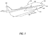
- FIG. 1 illustrates an example of a high speed flight vehicle 102.
- the flight vehicle 102 may be operated manned or unmanned as desired.
- the flight vehicle 102 is just one configuration of a flight vehicle capable of traveling at a speed of at least Mach 3, and other configurations, not shown, may be implemented as desired.
- the flight vehicle 102 may have a different shape, size, aspect ratio, etc., as desired.
- the flight vehicle 102 is merely shown in a particular configuration for purposes of discussion.
- the flight vehicle 102 provides one or more sources of heat when traveling at high speeds.
- source of heat may be provided by aerodynamic heating of a first surface 104 of the flight vehicle 102.
- the first surface 104 is provided on a leading surface, such as on a wing 106, tail 108, nose cap 110, or air inlet duct 112 of the flight vehicle 102.
- the first surface 104 may be aerodynamically heated to 1000 degrees Fahrenheit or more.
- another source of heat may be inlet air directed into the flight vehicle 102 when traveling at high speeds.
- the inlet air may include air traveling through the air inlet duct 112 or through other structures provided on the flight vehicle 102.
- the flight vehicle 102 includes an integrated cooling and power generation system 100 that cools and/or generates power from the one or more sources of heat.
- the system 100 cools the first surface 104, which allows the first surface 104 to be formed of materials that do not need to be rated for excessive temperature, lowering material cost and reducing material weight. Additionally or alternatively, converting the heat from the one or more sources of heat into electric power reduces the need for batteries or other conventional power sources and, consequently, the weight associated with such conventional power sources.
- the system 100 includes a power generation loop 120 through which is circulated a power generation loop working fluid 122.
- the power generation loop 120 is formed as a closed loop having a Brayton cycle architecture.
- heat from the one or more sources of heat is transferred to the power generation loop working fluid 122 in the power generation loop 120 to maintain the power generation loop working fluid 122 at a temperature and pressure above its critical point.
- the one or more sources of heat may be inlet air, the first surface 104, or other source.
- FIG. 3 graphically illustrates the critical point of a substance, where temperatures and pressures above the critical point will result in a supercritical state.
- the power generation loop working fluid 122 circulating through the power generation loop 120 is supercritical carbon dioxide.
- the system 100 includes components disposed in the power generation loop 120 for performing a sequence of thermodynamic processes involving transfer of heat and work into and out of the system 100, while varying temperature and pressure of the power generation loop working fluid 122 within the system.
- the system 100 includes a power generation loop compressor 130 for compressing the power generation loop working fluid 122 to an increased pressure.
- the power generation loop 120 further includes one or more heat intakes for absorbing heat from the one or more sources of heat.
- a first heat intake of the power generation loop 120 is an inlet air heat exchanger 256 that transfers heat from the inlet air to the power generation loop working fluid 122.
- an inlet air line 253 passes through the inlet air heat exchanger 256.
- An upstream end of the inlet air line 253 is fluidly coupled to an inlet air source, such as the air inlet duct 112.
- High temperature air systems 255 on board the flight vehicle 102 are fluidly coupled directly to the air inlet duct 112, thus bypassing the inlet air heat exchanger 256.
- Low temperature air systems 249 are fluidly coupled to a downstream end of the inlet air line 253.
- the inlet air heat exchanger 256 also includes an air-to-power generation loop line 251 that is located in thermally coupled relation to the inlet air line 253 to transfer heat from the inlet air to the power generation loop working fluid 122.
- the power generation loop 120 includes a second heat intake in the form of a first surface heat exchanger 140 that is located in thermally coupled relation to the first surface 104 of the flight vehicle 102.
- a power generation loop thermal engine 150 is disposed in the power generation loop 120 for extracting a power generation loop work output 152 from the power generation loop working fluid 122 by expanding the power generation loop working fluid 122 to a decreased pressure. While FIG. 2 schematically illustrates the power generation loop thermal engine 150 as a turbine, other types of thermal engines capable of extracting work output from a heated and pressurized working fluid may be used.
- the power generation loop work output 152 is in the form of a rotating output shaft of the turbine that is mechanically coupled to the power generation loop compressor 130 by a shaft 154 to operate the power generation loop compressor 130.
- the power generation loop compressor 130 may be electrically operated, in which case the power generation loop work output 152 is mechanically coupled to a generator, which converts the mechanical energy into electrical power to drive the power generation loop compressor 130. As discussed in greater detail below, that electrical power may be used to also power other vehicle systems.
- a generator 170 is operably coupled to the power generation loop thermal engine 150.
- the generator 170 receives at least a portion of the power generation loop work output 152 from the power generation loop thermal engine 150 and generates a source of electrical power 172.
- an auxiliary load 180 is operably coupled to the generator 170 and is configured to operate using the source of electrical power 172.
- the auxiliary load 180 may be an environmental control system (ECS), one or more flight control devices (e.g., actuators), an avionics system, a payload, or other device or system requiring electrical power.
- the source of electrical power 172 may also be used to power components of the integrated cooling and power generation system 100, such as the power generation loop compressor (130) and/or the heat transport loop compressor (254).
- the power generation loop compressor 130 and the power generation loop thermal engine 150 generally divide the power generation loop 120 into a low pressure leg 124, extending downstream of the power generation loop thermal engine 150 to an inlet of the power generation loop compressor 130, and a high pressure leg 126, extending upstream of the power generation loop thermal engine 150 to an outlet of the power generation loop compressor 130.
- the system 100 further includes a heat transport loop 250 through which is circulated a heat transport loop working fluid 252.
- the heat transport loop 250 is formed as a closed loop that also has a Brayton cycle architecture.
- the heat transport loop working fluid 252 in the heat transport loop 250 may also be a high-temperature working fluid, such as supercritical carbon dioxide.
- Components are disposed in the heat transport loop 250 for performing a sequence of thermodynamic processes involving transfer of heat and work into and out of the system 100, while varying temperature and pressure of the heat transport loop working fluid 252 within the system.
- the system 100 includes a heat transport loop compressor 254 for compressing the heat transport loop working fluid 252 to an increased pressure.
- the heat transport loop 250 further includes one or more heat intakes for absorbing heat from the one or more sources of heat.
- a first heat intake of the heat transport loop 250 is the inlet air heat exchanger 256 that transfers heat from the inlet air to the heat transport loop working fluid 252.
- the inlet air heat exchanger 256 includes an air-to-heat transport loop line 247 that is located in thermally coupled relation to the inlet air line 253 to transfer heat from the inlet air to the heat transport loop working fluid 252.
- the heat transport loop 250 includes a second heat intake in the form of a second surface heat exchanger 257 that is located in thermally coupled relation to the second surface 105 of the flight vehicle 102.
- a heat transport loop thermal engine 258 is disposed in the heat transport loop 250 for extracting a heat transport work output 260 from the heat transport loop working fluid 252 by expanding the heat transport loop working fluid 252 to a decreased pressure. While FIG. 2 schematically illustrates the heat transport loop thermal engine 258 as a turbine, other types of thermal engines capable of extracting work output from a heated and pressurized working fluid may be used.
- the heat transport work output 260 is in the form of a rotating output shaft of the turbine that is mechanically coupled to the heat transport loop compressor 254 by a shaft 259 to operate the power generation loop compressor 130.
- the heat transport loop compressor 254 and the heat transport loop thermal engine 258 generally divide the heat transport loop 250 into a low pressure leg 262, extending downstream of the heat transport loop thermal engine 258 to an inlet of the heat transport loop compressor 254, and a high pressure leg 263, extending upstream of the heat transport loop thermal engine 258 to an outlet of the heat transport loop compressor 254.
- the system 100 further includes a heat sink heat exchanger 190 for removing excess heat from the power generation loop working fluid 122 and the heat transport loop working fluid 252.
- the heat sink heat exchanger 190 is disposed in the low pressure legs 124, 262, respectively, of the power generation loop 120 and heat transport loop 250.
- the heat sink heat exchanger 190 ensures that the temperatures of the power generation loop working fluid 122 and the heat transport loop working fluid 252 do not exceed the rated operating temperature ranges for the power generation loop compressor 130 and the heat transport loop compressors 254. Additionally, the excess heat may be rejected to the surrounding atmosphere or transferred to a secondary fluid in another system on board the flight vehicle 102.
- the heat sink heat exchanger 190 further includes a heat sink line 191 passing through the heat sink heat exchanger 190.
- An upstream end of the heat sink line 191 fluidly communicates with one or more heat sink fluid tanks 192 carrying heat sink fluid (e.g., fuel, water, or other fluid carried on board the flight vehicle 102).
- the upstream end of the heat sink line 191 further may communicate with subsystem heat loads 194.
- a downstream end of the heat sink line 191 may fluidly communicate with other vehicle systems using hot heat sink fluid 196, and which can utilize heated heat sink fluid.
- the heat sink heat exchanger 190 includes a heat sink-to-power generation loop line 187 and a heat sink-to-heat transport loop line 189, both of which are located in thermally coupled relation to the heat sink line 191 to transfer heat from the inlet air to the power generation loop working fluid 122 and the heat transport loop working fluid 252, respectively.
- a controller 200 is provided to control operation of the system 100.
- the controller 200 is operably coupled to the power generation loop compressor 130 and the heat transport loop compressor 254, and is programmed to execute a method that includes initiating operation of the power generation loop compressor 130 and the heat transport loop compressor 254 when one or more operating conditions of the flight vehicle 102 is favorable for maintaining the power generation loop working fluid 122 and the heat transport loop working fluid 252 in supercritical states.
- the operating condition is temperature of the one or more sources of heat, such as inlet air temperature or a temperature of the first or second surfaces 104, 105, in which case the controller 200 receives feedback from a sensor 202 configured to detect temperature and is programmed to start the power generation loop compressor 130 and heat transport loop compressor 254 when the detected temperature exceeds a threshold temperature.
- Exemplary threshold temperatures include, but are not limited to, 500 degrees F, 600 degrees F, 700 degrees F, 800 degrees F, 900 degrees F, and 1000 degrees F.
- the operating condition is a flight speed of the flight vehicle 102, which is indicative of a temperature of the one or more sources of heat.
- the controller 200 receives an indication of flight speed, such as from an input command or sensor 202 when configured to determine flight speed, and is programmed to start the power generation loop compressor 130 and the heat transport loop compressor 254 when the flight vehicle 102 reaches a threshold flight speed.
- exemplary threshold flight speeds include, but are not limited to, Mach 3, Mach 3.5, Mach 4, and hypersonic speed (i.e., Mach 5 or greater).
- the controller 200 may be operably coupled to the power generation loop thermal engine 150 and the heat transport loop thermal engine 258.
- the controller 200 further is operably coupled to the generator 170 and the auxiliary load 180 to control operation or other aspects of those components. Because of the thermal efficiency, compact size, and reduced weight afforded by the use of a supercritical working fluid as the power generation loop working fluid 122 and the heat transport loop working fluid 252, the integrated cooling and power generation system 100 achieves gravimetric and volumetric power densities that are an order of magnitude greater than batteries or other conventional power sources.
- the one or more processors may include any electronic circuits and/or optical circuits that are able to perform the functions described herein.
- the processor(s) may perform any functionality described herein for controller 200.
- the processor(s) may include one or more Central Processing Units (CPU), microprocessors, Digital Signal Processors (DSPs), Application-specific Integrated Circuits (ASICs), Programmable Logic Devices (PLD), control circuitry, etc.
- CPU Central Processing Units
- DSPs Digital Signal Processors
- ASICs Application-specific Integrated Circuits
- PLD Programmable Logic Devices
- Some examples of processors include INTEL ® CORE TM processors, Advanced Reduced Instruction Set Computing (RISC) Machines (ARM ® ) processors, etc.
- the system 100 is configured to maintain the power generation loop working fluid 122 and the heat transport loop working fluid 252 in supercritical states during the entire thermodynamic cycle, enabling the use of lighter and more compact turbomachinery.
- the power generation loop working fluid 122 and the heat transport loop working fluid 252 are carbon dioxide, for example, the critical temperature is approximately 88 degrees F and the critical pressure is approximately 74 bar.
- Temperature of the one or more sources of heat increases with the speed of the flight vehicle 102. For example, at a speed of Mach 3.5, inlet air and/or the first and second surfaces 104, 105 may reach 750 degrees F or more, which would be sufficient to maintain the power generation loop working fluid 122 and the heat transport loop working fluid 252 in supercritical states.
- the temperature of the one or more sources of heat may reach 1000 degrees Fahrenheit. Thermodynamic efficiency of the system 100 increases with the temperature of the one or more sources of heat.
- the power generation loop compressor 130 and the heat transport loop compressor 254 are sized to maintain pressures of the power generation loop working fluid 122 and the heat transport loop working fluid 252 above the critical pressures throughout the thermodynamic cycle. Because the power generation loop working fluid 122 and the heat transport loop working fluid 252 are in supercritical states, the power generation loop compressor 130, the heat transport loop compressor 254, the power generation loop thermal engine 150, and the heat transport loop thermal engine 258, may have a reduced sizes and weights, making the system 100 feasible for use on board the flight vehicle 102.
- the illustrated system 100 is a closed loop system that is provided independent of a propulsion system of the flight vehicle 102.
- Operating conditions for the power generation loop and the heat transport loop may be optimized for their respective primary functions.
- the power generation loop working fluid 122 may have a higher pressure ratio than the heat transport loop working fluid 252.
- the power generation loop working fluid 122 may have a pressure ratio of approximately 3 while the heat transport loop working fluid 252 may have a pressure ratio of approximately 1.
- the term "pressure ratio" means the ratio of inlet to outlet pressure across the compressor (i.e., the power generation loop compressor 130 and the heat transport loop compressor 254).
- FIG. 4 is a block diagram illustrating a method 300 of power generation and/or thermal management on board the flight vehicle 102.
- the method 300 begins at block 302 by advancing the flight vehicle 102 at a flight speed of at least Mach 3, during which the one or more sources of heat increase in temperature.
- a first working fluid such as the power generation loop working fluid 122, is circulated through a first loop, such as the power generation loop 120.
- Circulating the first working fluid through the first loop includes, in sequence, compressing the first working fluid through a first compressor (e.g., compressing the power generation loop working fluid 122 through the power generation loop compressor 130) as shown at block 306; heating the first working fluid through a first heat intake of the first loop, wherein the first heat intake is thermally coupled to at least one heat source associated with the flight vehicle 102 (e.g., heating the power generation loop working fluid 122 through the one or more heat intakes of the power generation loop 120) as shown at block 308; and expanding the first working fluid in a first thermal engine to generate a first work output from the first thermal engine (e.g., expanding the power generation loop working fluid 122 in the power generation loop thermal engine 150 to generate a power generation loop work output 152 from the power generation loop thermal engine 150) as shown at block 310.
- a first compressor e.g., compressing the power generation loop working fluid 122 through the power generation loop compressor 130
- heating the first working fluid through a first heat intake of the first loop
- Circulating the first working fluid through the first loop 304 further includes cooling the first working fluid (e.g., cooling the power generation loop working fluid 122) as shown at block 312, and recirculating the first working fluid to the first compressor (e.g., recirculating the power generation loop working fluid 122 to the power generation loop compressor 130) as shown at block 314.
- cooling the first working fluid e.g., cooling the power generation loop working fluid 122
- recirculating the first working fluid to the first compressor e.g., recirculating the power generation loop working fluid 122 to the power generation loop compressor 130
- the method 300 further may continue at block 330 by circulating a second working fluid through a second loop (e.g., circulating the heat transport loop working fluid 252 through the heat transport loop 250).
- Circulating the second working fluid through the second loop includes, in sequence, compressing the second working fluid through a second compressor (e.g., compressing the heat transport loop working fluid 252 through the heat transport loop compressor 254) as shown at block 332; heating the second working fluid through a second heat intake of the second loop, wherein the second heat intake is thermally coupled to at least one heat source associated with the flight vehicle 102 (e.g., heating the heat transport loop working fluid 252 through the one or more heat intakes of the heat transport loop 250) as shown at block 334; and expanding the second working fluid in a second thermal engine to generate a second work output from the second thermal engine (e.g., expanding the heat transport loop working fluid 252 in the heat transport loop thermal engine 258 to generate a heat transport work output 260 from the heat transport loop thermal engine 258) as shown at block 3
- Circulating the second working fluid through the second loop further includes cooling the second working fluid (e.g., cooling the heat transport loop working fluid 252) as shown at block 338, and recirculating the second working fluid to the second compressor (e.g., recirculating the heat transport loop working fluid 252 to the heat transport loop compressor 254) as shown at block 340.
- cooling the second working fluid e.g., cooling the heat transport loop working fluid 252
- recirculating the second working fluid to the second compressor e.g., recirculating the heat transport loop working fluid 252 to the heat transport loop compressor 254
- the method 300 further includes generating electrical power.
- the method 300 includes generating electric power by operably coupling the first thermal engine to a generator (e.g., generating the source of electric power 172 by mechanically coupling the power generation loop work output 152 of the power generation loop thermal engine 150 to the generator 170) as shown at block 318.
- the source of electrical power 172 from the generator 170 may be used to operate the power generation loop compressor 130 and/or the heat transport loop compressor 254, when those components are powered electrically. Additionally or alternatively, the source of electric power 172 may be used to power an auxiliary load 180.
- the method 300 includes operably coupling the second work output of the second thermal engine to the second compressor (e.g., operably coupling the heat transport work output 260 of the heat transport loop thermal engine 258 to the heat transport loop compressor 254) as shown at block 342.
- the method 300 may optionally include additional steps to reduce the temperature of the first working fluid and the second working fluid prior to being recirculated back to the first compressor and the second compressor, respectively. More specifically, the method 300 may include rejecting heat from the first working fluid via a heat sink heat exchanger (e.g., rejecting heat from the power generation loop working fluid 122 using the heat sink heat exchanger 190) as shown at block 322, and rejecting heat from the second working fluid via the heat sink heat exchanger (e.g., rejecting heat from the heat transport loop working fluid 252 using the heat sink heat exchanger 190) as shown at block 346.
- a heat sink heat exchanger e.g., rejecting heat from the power generation loop working fluid 122 using the heat sink heat exchanger 190
- rejecting heat from the second working fluid via the heat sink heat exchanger e.g., rejecting heat from the heat transport loop working fluid 252 using the heat sink heat exchanger 190
- first loop and second loop are intended to refer to either one of the power generation loop 120 and the heat transport loop 250. That is, while the above examples identify the power generation loop 120 as the “first loop” and the heat transport loop 250 as the “second loop,” in alternative examples the heat transport loop 250 is the “first loop” and the power generation loop is the "second loop.”
- first working fluid and second working fluid are intended to refer to either one of the power generation loop working fluid 122 and the heat transport loop working fluid 252. That is, while the above examples identify the power generation loop working fluid 122 as the “first working fluid” and the heat transport loop working fluid 252 as the “second working fluid,” in alternative examples the heat transport loop working fluid 252 is “the first working fluid” and the power generation working fluid is “the second working fluid.”
- first compressor and second compressor are intended to refer to either one of the power generation loop compressor 130 and the heat transport loop compressor 254. That is, while the above examples identify the power generation loop compressor 130 as the “first compressor” and the heat transport loop compressor 254 as the “second compressor,” in alternative examples the heat transport loop compressor 254 is the “first compressor” and the power generation loop compressor 130 is the “second compressor.”
- first thermal engine and second thermal engine are intended to refer to either one of the power generation loop thermal engine 150 and the heat transport loop thermal engine 258. That is, while the above examples identify the power generation loop thermal engine 150 as the “first thermal engine” and the heat transport loop thermal engine 258 as the “second thermal engine,” in alternative examples the heat transport loop thermal engine 258 is the “first thermal engine” and the power generation loop thermal engine 150 is the “second thermal engine.”
- Example 1 A method of providing at least one of cooling and generating power on board a flight vehicle using heated inlet air associated with the flight vehicle, the method comprising: advancing the flight vehicle at a flight speed of at least Mach 3; circulating a first working fluid through a first fluid loop including, in sequence: compressing the first working fluid through a first compressor; heating the first working fluid through an inlet air heat exchanger, the inlet air heat exchanger including an inlet air line fluidly communicating with the heated inlet air and a first air-to-loop line located in thermally coupled relation to the inlet air line; expanding the first working fluid in a first loop thermal engine to generate a first work output from the first thermal engine; cooling the first working fluid; and recirculating the first working fluid to the first compressor.
- Example 2 The method of example 1, in which the first fluid loop comprises a power generation loop, and in which the method further comprises generating electric power by operably coupling the first work output of the first thermal engine to a generator.
- Example 3 The method of any of examples 1-2, in which the first fluid loop comprises a heat transport loop, and in which the method further comprises operably coupling the first work output of the first thermal engine to the first compressor.
- Example 4 The method of any of examples 1-3, further comprising: circulating a second working fluid through a second fluid loop including, in sequence: compressing the second working fluid through a second compressor; heating the second working fluid through the inlet air heat exchanger, the inlet air heat exchanger including a second air-to-loop line; expanding the second working fluid in a second thermal engine to generate a second work output from the second thermal engine; cooling the second working fluid; and recirculating the second working fluid to the second compressor.
- Example 5 The method of example 4, in which the first fluid loop comprises a power generation loop and the second fluid loop comprises a heat transport loop, the method further comprising: generating electric power by operably coupling the first work output of the first thermal engine of the power generation loop to a generator; and operably coupling the second work output of the second thermal engine to the second compressor.
- Example 6 The method of example 5, further comprising powering an auxiliary load using the generator.
- Example 7 The method of any of examples 4-6, in which the first working fluid comprises a first supercritical working fluid and the second working fluid comprises a second supercritical working fluid.
- Example 8 The method of any of examples 4-7, further comprising: rejecting heat from the first working fluid via a heat sink heat exchanger prior to recirculating the first working fluid to the first compressor; and rejecting heat from the second working fluid via the heat sink heat exchanger prior to recirculating the second working fluid to the second compressor.
- Example 9 A system for providing at least one of cooling and generating power on board a flight vehicle using heated inlet air associated with the flight vehicle traveling at a flight speed of at least Mach 3, the system comprising: a first fluid loop containing a first working fluid, the first fluid loop including, in sequence: a first compressor for compressing the first working fluid; an inlet air heat exchanger, the inlet air heat exchanger including an inlet air line fluidly communicating with the heated inlet air, and a first air-to-loop line receiving the first working fluid and located in thermally coupled relation to the inlet air line; and a first thermal engine for expanding the first working fluid and generating a first work output.
- Example 10 The system of example 9, in which the first fluid loop comprises a power generation loop, the system further comprising a generator operably coupled to the first work output and configured to generate electrical power.
- Example 11 The system of example 9, in which the first fluid loop comprises a heat transport loop, and in which the first work output of the first thermal engine is operably coupled to the first compressor.
- Example 12 The system of any of examples 9-11, further comprising: a second fluid loop containing a second working fluid, the second fluid loop including, in sequence: a second compressor for compressing the second working fluid; the inlet air heat exchanger, the inlet air heat exchanger including a second air-to-loop line receiving the second working fluid and located in thermally coupled relation to the inlet air line; and a second thermal engine for expanding the second working fluid and generating a second work output.
- a second fluid loop containing a second working fluid the second fluid loop including, in sequence: a second compressor for compressing the second working fluid; the inlet air heat exchanger, the inlet air heat exchanger including a second air-to-loop line receiving the second working fluid and located in thermally coupled relation to the inlet air line; and a second thermal engine for expanding the second working fluid and generating a second work output.
- Example 13 The system of example 12, in which the first fluid loop comprises a power generation loop and the second fluid loop comprises a heat transfer loop, the system further comprising a generator operably coupled to the first work output and configured to generate electrical power, and in which the second work output of the second thermal engine is operably coupled to the second compressor.
- Example 14 The system of example 13, further comprising a first surface heat exchanger, located in thermally coupled relation to a first surface of the flight vehicle, for heating the first working fluid of the power generation loop.
- Example 15 The system of example 14, further comprising a second surface heat exchanger, located in thermally coupled relation to a second surface of the flight vehicle, for heating the second working fluid of the heat transfer loop.
- Example 16 The system of example 15, further comprising a heat sink heat exchanger, the heat sink heat exchanger including: a heat sink line fluidly communicating with a heat sink fluid tank; a heat sink-to-power generation loop line receiving the first working fluid and located in thermally coupled relation to the heat sink line; and a heat sink-to-heat transport loop line receiving the second working fluid and located in thermally coupled relation to the heat sink line.
- a heat sink heat exchanger including: a heat sink line fluidly communicating with a heat sink fluid tank; a heat sink-to-power generation loop line receiving the first working fluid and located in thermally coupled relation to the heat sink line; and a heat sink-to-heat transport loop line receiving the second working fluid and located in thermally coupled relation to the heat sink line.
- Example 17 The system of any of examples 9-16, further comprising a controller operably coupled to the first and second compressors, wherein the controller is programmed to execute a method, comprising initiating operation of the first and second compressors when an operating condition of the flight vehicle exceeds an operating threshold.
- Example 18 A system for providing cooling and generating power on board a flight vehicle using heated inlet air associated with the flight vehicle traveling at a flight speed of at least Mach 3, the system comprising: a power generation loop containing a power generation loop working fluid, the power generation loop including, in sequence: a power generation loop compressor for compressing the power generation loop working fluid; an inlet air heat exchanger, the inlet air heat exchanger including an inlet air line fluidly communicating with the heated inlet air, and a first air-to-loop line receiving the power generation loop working fluid and located in thermally coupled relation to the inlet air line; and a power generation loop thermal engine for expanding the power generation loop working fluid and generating a power generation loop work output; a heat transport loop containing a heat transport loop working fluid, the heat transport loop including, in sequence: a heat transport loop compressor for compressing the heat transport loop working fluid; the inlet air heat exchanger, the inlet air heat exchanger including a second air-to-loop line receiving the heat transport loop working fluid and located in thermally coupled relation to
- Example 19 The system of example 18, further comprising an auxiliary load operably coupled to the generator.
- Example 20 The system of any of examples 18-19, further comprising a heat sink heat exchanger, the heat sink heat exchanger including: a heat sink line fluidly communicating with a heat sink fluid tank; a heat sink-to-power generation loop line receiving the power generation loop working fluid and located in thermally coupled relation to the heat sink line; and a heat sink-to-heat transport loop line receiving the heat transport loop working fluid and located in thermally coupled relation to the heat sink line.
- the heat sink heat exchanger including: a heat sink line fluidly communicating with a heat sink fluid tank; a heat sink-to-power generation loop line receiving the power generation loop working fluid and located in thermally coupled relation to the heat sink line; and a heat sink-to-heat transport loop line receiving the heat transport loop working fluid and located in thermally coupled relation to the heat sink line.
- sequence generally refers to elements (e.g., unit operations) in order. Such order can refer to process order, such as, for example, the order in which a working fluid flows from one element to another.
- a compressor, heat storage unit and turbine in sequence includes the compressor upstream of the heat exchange unit, and the heat exchange unit upstream of the turbine.
- a working fluid can flow from the compressor to the heat exchange unit and from the heat exchange unit to the turbine.
- a working fluid flowing through unit operations in sequence can flow through the unit operations sequentially.
- a sequence of elements can include one or more intervening elements.
- a system comprising a compressor, heat storage unit and turbine in sequence can include an auxiliary tank between the compressor and the heat storage unit.
- a sequence of elements can be cyclical.
- any of the various elements shown in the figures or described herein may be implemented as hardware, software, firmware, or some combination of these.
- an element may be implemented as dedicated hardware.
- Dedicated hardware elements may be referred to as "processors", “controllers”, or some similar terminology.
- processors When provided by a processor, the functions may be provided by a single dedicated processor, by a single shared processor, or by a plurality of individual processors, some of which may be shared.
- processor or “controller” should not be construed to refer exclusively to hardware capable of executing software, and may implicitly include, without limitation, digital signal processor (DSP) hardware, a network processor, application specific integrated circuit (ASIC) or other circuitry, field programmable gate array (FPGA), read only memory (ROM) for storing software, random access memory (RAM), non-volatile storage, logic, or some other physical hardware component or module.
- DSP digital signal processor
- ASIC application specific integrated circuit
- FPGA field programmable gate array
- ROM read only memory
- RAM random access memory
- non-volatile storage logic, or some other physical hardware component or module.
- an element may be implemented as instructions executable by a processor or a computer to perform the functions of the element.
- Some examples of instructions are software, program code, and firmware.
- the instructions are operational when executed by the processor to direct the processor to perform the functions of the element.
- the instructions may be stored on storage devices that are readable by the processor. Some examples of the storage devices are digital or solid-state memories, magnetic storage media such as a magnetic disks and magnetic tapes, hard drives, or optically readable digital data storage media.
Landscapes
- Engineering & Computer Science (AREA)
- Chemical & Material Sciences (AREA)
- Combustion & Propulsion (AREA)
- Mechanical Engineering (AREA)
- General Engineering & Computer Science (AREA)
- Chemical Kinetics & Catalysis (AREA)
- Engine Equipment That Uses Special Cycles (AREA)
Applications Claiming Priority (1)
| Application Number | Priority Date | Filing Date | Title |
|---|---|---|---|
| US202063117238P | 2020-11-23 | 2020-11-23 |
Publications (2)
| Publication Number | Publication Date |
|---|---|
| EP4001613A1 true EP4001613A1 (fr) | 2022-05-25 |
| EP4001613B1 EP4001613B1 (fr) | 2024-06-19 |
Family
ID=77821637
Family Applications (1)
| Application Number | Title | Priority Date | Filing Date |
|---|---|---|---|
| EP21197403.5A Active EP4001613B1 (fr) | 2020-11-23 | 2021-09-17 | Procédés et systèmes de génération de puissance et de gestion thermique ayant une architecture à double boucle |
Country Status (3)
| Country | Link |
|---|---|
| US (2) | US12031477B2 (fr) |
| EP (1) | EP4001613B1 (fr) |
| CN (1) | CN114526176B (fr) |
Families Citing this family (2)
| Publication number | Priority date | Publication date | Assignee | Title |
|---|---|---|---|---|
| US12209533B2 (en) * | 2022-11-29 | 2025-01-28 | General Electric Company | Heat driven thermal management systems and methods for operating the same |
| US12589872B2 (en) * | 2023-09-29 | 2026-03-31 | The Boeing Company | Method and system for reducing a temperature differential across a flight vehicle |
Citations (2)
| Publication number | Priority date | Publication date | Assignee | Title |
|---|---|---|---|---|
| US7963100B2 (en) * | 2005-05-25 | 2011-06-21 | Alliant Techsystems Inc. | Cooling system for high-speed vehicles and method of cooling high-speed vehicles |
| EP3757010A1 (fr) * | 2019-06-28 | 2020-12-30 | The Boeing Company | Systèmes et procédés de refroidissement et de génération d'énergie sur des véhicules volant à grande vitesse |
Family Cites Families (49)
| Publication number | Priority date | Publication date | Assignee | Title |
|---|---|---|---|---|
| DE3018450C2 (de) | 1980-05-14 | 1985-10-03 | Bergwerksverband Gmbh, 4300 Essen | Verfahren zur Bereitstellung von Prozeßwärme für Hochtemperaturprozesse unter Verwendung einer Wärmepumpe |
| US4827723A (en) | 1988-02-18 | 1989-05-09 | A. Ahlstrom Corporation | Integrated gas turbine power generation system and process |
| JP2002022298A (ja) | 2000-07-04 | 2002-01-23 | Matsushita Electric Ind Co Ltd | 冷凍サイクル装置とその制御方法 |
| US7416137B2 (en) | 2003-01-22 | 2008-08-26 | Vast Power Systems, Inc. | Thermodynamic cycles using thermal diluent |
| WO2007035298A2 (fr) | 2005-09-09 | 2007-03-29 | Lugg Richard H | Moteur turbine electrique / a reaction magnetique hypersonique avance |
| US7624592B2 (en) | 2006-05-17 | 2009-12-01 | Northrop Grumman Corporation | Flexible power and thermal architectures using a common machine |
| US7607318B2 (en) | 2006-05-25 | 2009-10-27 | Honeywell International Inc. | Integrated environmental control and auxiliary power system for an aircraft |
| JP2009191611A (ja) | 2007-09-13 | 2009-08-27 | Hiroyasu Tanigawa | 各種エネルギ保存サイクル合体機関 |
| US8127555B2 (en) | 2007-12-13 | 2012-03-06 | Pratt & Whitney Rocketdyne, Inc. | Flowpath heat exchanger for thermal management and power generation within a hypersonic vehicle |
| CN101301931A (zh) | 2008-04-28 | 2008-11-12 | 全力 | 复合涡流的制造方法、制造设备及复合涡流飞行器 |
| US8327651B2 (en) | 2009-07-07 | 2012-12-11 | Hamilton Sundstrand Corporation | Transcritical fluid cooling for aerospace applications |
| US20170292412A1 (en) | 2009-10-27 | 2017-10-12 | Eduardo E. Fonseca | Aircraft Engine Heat Recovery System to Power Environmental Control Systems |
| CA2792331C (fr) | 2010-03-05 | 2017-12-12 | Exxonmobil Upstream Research Company | Installation souple pour gaz naturel liquefie |
| US8522572B2 (en) | 2010-07-01 | 2013-09-03 | General Electric Company | Adaptive power and thermal management system |
| US8935928B2 (en) * | 2011-10-10 | 2015-01-20 | Lockheed Martin Corporation | Integrated air-cycle refrigeration and power generation system |
| BR112015015613A2 (pt) | 2012-12-28 | 2017-07-11 | Gen Electric | sistema de potência elétrica para uma aeronave e método para produzir potência elétrica em uma aeronave |
| BR112015015516A2 (pt) | 2012-12-28 | 2017-07-11 | Gen Electric | conjunto de mecanismo motor de turbina |
| US9718553B2 (en) | 2013-03-14 | 2017-08-01 | Rolls-Royce North America Technologies, Inc. | Adaptive trans-critical CO2 cooling systems for aerospace applications |
| US20160045841A1 (en) | 2013-03-15 | 2016-02-18 | Transtar Group, Ltd. | New and improved system for processing various chemicals and materials |
| US20160025339A1 (en) | 2013-03-15 | 2016-01-28 | General Electric Company | Energy-efficient and controlled vaporization of cryofuels for aircraft engines |
| GB2519150A (en) * | 2013-10-11 | 2015-04-15 | Reaction Engines Ltd | Rotational machine |
| US20150315971A1 (en) | 2013-10-21 | 2015-11-05 | Government Of The United States As Represented By The Secretary Of The Air Force | High-speed vehicle power and thermal management system and methods of use therefor |
| US9739200B2 (en) | 2013-12-30 | 2017-08-22 | Rolls-Royce Corporation | Cooling systems for high mach applications |
| US10054051B2 (en) | 2014-04-01 | 2018-08-21 | The Boeing Company | Bleed air systems for use with aircraft and related methods |
| US9810158B2 (en) | 2014-04-01 | 2017-11-07 | The Boeing Company | Bleed air systems for use with aircraft and related methods |
| US20150315966A1 (en) | 2014-05-01 | 2015-11-05 | The Boeing Company | Hypersonic Vehicle Base Drag Reduction and Improved Inlet Performance Through Venting Forebody Bleed Air to Base Area Using Open Core Ceramic Composites |
| NO3136728T3 (fr) | 2014-06-30 | 2018-07-28 | ||
| CN107428415B (zh) | 2015-03-30 | 2021-11-19 | 空中客车德国运营有限责任公司 | 具有冗余的有效引气系统的飞行器 |
| US11208893B2 (en) | 2015-05-25 | 2021-12-28 | Socpra Sciences Et Genie S.E.C. | High temperature ceramic rotary turbomachinery |
| US10100744B2 (en) | 2015-06-19 | 2018-10-16 | The Boeing Company | Aircraft bleed air and engine starter systems and related methods |
| US9758235B2 (en) | 2015-10-13 | 2017-09-12 | The Boeing Company | Thermal insulation system, aircraft, and vehicle having same |
| DE102015223548A1 (de) | 2015-11-27 | 2017-06-01 | Airbus Operations Gmbh | Flugzeugklimaanlage mit Umgebungsluftzufuhr und Verfahren zum Betreiben einer derartigen Flugzeugklimaanlage |
| CN106640242B (zh) | 2016-09-19 | 2018-02-09 | 清华大学 | 高超声速飞行器发动机热量回收发电系统及其控制方法 |
| US10329022B2 (en) | 2016-10-31 | 2019-06-25 | Honeywell International Inc. | Adjustable sensor or sensor network to selectively enhance identification of select chemical species |
| US10221775B2 (en) | 2016-12-29 | 2019-03-05 | Malta Inc. | Use of external air for closed cycle inventory control |
| US20180215475A1 (en) | 2017-02-01 | 2018-08-02 | General Electric Company | Systems and Methods for Integrated Power and Thermal Management in a Turbine-Powered Aircraft |
| CN107150810B (zh) | 2017-04-06 | 2018-06-22 | 清华大学 | 飞行器热部件的防护系统 |
| US10926480B2 (en) | 2017-09-05 | 2021-02-23 | The Boeing Company | Methods for manufacturing components having spatially graded properties |
| CN107914862B (zh) | 2017-11-20 | 2020-09-18 | 北京临近空间飞行器系统工程研究所 | 一种全主动冷却高超声速飞行器 |
| US10704466B2 (en) * | 2018-01-29 | 2020-07-07 | Rolls-Royce North American Technologies Inc. | High-mach vehicle cooling |
| CN108298061B (zh) | 2018-01-30 | 2020-03-24 | 南京普国科技有限公司 | 高超声速飞行器及其热防护和热生电装置 |
| US10941706B2 (en) * | 2018-02-13 | 2021-03-09 | General Electric Company | Closed cycle heat engine for a gas turbine engine |
| CN108657442B (zh) | 2018-05-16 | 2020-11-24 | 中国航发湖南动力机械研究所 | 飞行器及热防护系统 |
| EP3572329A1 (fr) | 2018-05-24 | 2019-11-27 | Rolls-Royce plc | Système de réglage environnemental d'un aéronef |
| CN108750123B (zh) | 2018-06-07 | 2020-10-23 | 北京航空航天大学 | 适用于高超声速飞行器的热能综合管理系统及飞行器 |
| US20200224590A1 (en) * | 2019-01-16 | 2020-07-16 | United Technologies Corporation | Work recovery system for a gas turbine engine utilizing a recuperated supercritical co2 cycle driven by cooled cooling air waste heat |
| CN109989833A (zh) | 2019-04-24 | 2019-07-09 | 北京航空航天大学 | 一种用于高超声速飞行器或发动机的综合热管理系统 |
| US11969796B2 (en) | 2020-01-03 | 2024-04-30 | The Boeing Company | Tuned multilayered material systems and methods for manufacturing |
| US11571742B2 (en) | 2020-01-03 | 2023-02-07 | The Boeing Company | Tuned multilayered material systems and methods for manufacturing |
-
2021
- 2021-09-17 EP EP21197403.5A patent/EP4001613B1/fr active Active
- 2021-10-27 CN CN202111253421.1A patent/CN114526176B/zh active Active
- 2021-11-23 US US17/533,676 patent/US12031477B2/en active Active
-
2024
- 2024-06-12 US US18/740,615 patent/US12595759B2/en active Active
Patent Citations (2)
| Publication number | Priority date | Publication date | Assignee | Title |
|---|---|---|---|---|
| US7963100B2 (en) * | 2005-05-25 | 2011-06-21 | Alliant Techsystems Inc. | Cooling system for high-speed vehicles and method of cooling high-speed vehicles |
| EP3757010A1 (fr) * | 2019-06-28 | 2020-12-30 | The Boeing Company | Systèmes et procédés de refroidissement et de génération d'énergie sur des véhicules volant à grande vitesse |
Also Published As
| Publication number | Publication date |
|---|---|
| US20240328348A1 (en) | 2024-10-03 |
| EP4001613B1 (fr) | 2024-06-19 |
| CN114526176B (zh) | 2026-01-02 |
| US12595759B2 (en) | 2026-04-07 |
| US20220260037A1 (en) | 2022-08-18 |
| CN114526176A (zh) | 2022-05-24 |
| US12031477B2 (en) | 2024-07-09 |
Similar Documents
| Publication | Publication Date | Title |
|---|---|---|
| CA3081951C (fr) | Systemes et procedes de refroidissement et de generation de puissance pour vehicules de vol en regime de croisiere rapide | |
| US12595759B2 (en) | Methods and systems for generating power and thermal management having dual loop architecture | |
| US11598285B2 (en) | Methods and systems for generating power and thermal management having combined cycle architecture | |
| CN109677639B (zh) | 基于闭式布雷顿循环的空间大功率核动力系统 | |
| CN108750123B (zh) | 适用于高超声速飞行器的热能综合管理系统及飞行器 | |
| US9669936B1 (en) | Aircraft air conditioning systems and methods | |
| US20200385127A1 (en) | Advanced FuelCell Integration Into Aircraft | |
| EP1283166B1 (fr) | Conditionnement d'une alimentation d'air | |
| CA2785328A1 (fr) | Systemes de refroidissement a double usage | |
| US20180362166A1 (en) | High efficiency electrically driven environmental control system | |
| CA3249048A1 (fr) | Système de gestion thermique des avions à pile à combustible | |
| EP3866235A1 (fr) | Système de génération électrique comprenant une pile à combustible et un système de régulation thermique | |
| US20250059933A1 (en) | Method of Nacelle Air Heat Exchanger Integration for a Hydrogen Fueled Fuel Cell Powered Aircraft | |
| EP4530182A1 (fr) | Procédé et système de réduction d'un différentiel de température à travers un véhicule volant | |
| Wang et al. | Coupling study of onboard power generation system of Magnetohydrodynamics enhanced Brayton Cycle | |
| Kojima et al. | Investigation of Weight and Flight-Path Constraints on Liquid Hydrogen Fueled SOFC/GT Hybrid Propulsion System | |
| Giuffré et al. | Thermal Management System Architecture for the Powertrain of a 90-Seater Battery-Electric Aircraft | |
| Hao et al. | Retrofitting a Turboshaft Engine to An Engine-Fuel Cell Hybrid: A Case Study | |
| EP4506253A1 (fr) | Turbogénérateur à ultra-haute température | |
| EP4678897A1 (fr) | Cycle de fond cryogenique partage | |
| US3106073A (en) | Aircraft systems incorporating pressure exchangers | |
| Yu et al. | Thermal Control System for Electrical Components of Hybrid-Electric Powered Low Carbon Air Vehicle | |
| EP4510251A2 (fr) | Démarrage d'un aéronef à pile à combustible à membrane échangeuse de protons à haute température (htpem) doté de multiples unités de génération d'énergie | |
| Fagan et al. | Integrated Thermal Aero Propulsion (ITAP) Engine | |
| Fawal et al. | Extended Second Law Analysis for Turboramjet Engines |
Legal Events
| Date | Code | Title | Description |
|---|---|---|---|
| PUAI | Public reference made under article 153(3) epc to a published international application that has entered the european phase |
Free format text: ORIGINAL CODE: 0009012 |
|
| STAA | Information on the status of an ep patent application or granted ep patent |
Free format text: STATUS: THE APPLICATION HAS BEEN PUBLISHED |
|
| AK | Designated contracting states |
Kind code of ref document: A1 Designated state(s): AL AT BE BG CH CY CZ DE DK EE ES FI FR GB GR HR HU IE IS IT LI LT LU LV MC MK MT NL NO PL PT RO RS SE SI SK SM TR |
|
| STAA | Information on the status of an ep patent application or granted ep patent |
Free format text: STATUS: REQUEST FOR EXAMINATION WAS MADE |
|
| 17P | Request for examination filed |
Effective date: 20220725 |
|
| RBV | Designated contracting states (corrected) |
Designated state(s): AL AT BE BG CH CY CZ DE DK EE ES FI FR GB GR HR HU IE IS IT LI LT LU LV MC MK MT NL NO PL PT RO RS SE SI SK SM TR |
|
| RAP3 | Party data changed (applicant data changed or rights of an application transferred) |
Owner name: THE BOEING COMPANY |
|
| GRAP | Despatch of communication of intention to grant a patent |
Free format text: ORIGINAL CODE: EPIDOSNIGR1 |
|
| STAA | Information on the status of an ep patent application or granted ep patent |
Free format text: STATUS: GRANT OF PATENT IS INTENDED |
|
| INTG | Intention to grant announced |
Effective date: 20231215 |
|
| GRAJ | Information related to disapproval of communication of intention to grant by the applicant or resumption of examination proceedings by the epo deleted |
Free format text: ORIGINAL CODE: EPIDOSDIGR1 |
|
| STAA | Information on the status of an ep patent application or granted ep patent |
Free format text: STATUS: REQUEST FOR EXAMINATION WAS MADE |
|
| INTC | Intention to grant announced (deleted) | ||
| GRAP | Despatch of communication of intention to grant a patent |
Free format text: ORIGINAL CODE: EPIDOSNIGR1 |
|
| STAA | Information on the status of an ep patent application or granted ep patent |
Free format text: STATUS: GRANT OF PATENT IS INTENDED |
|
| GRAS | Grant fee paid |
Free format text: ORIGINAL CODE: EPIDOSNIGR3 |
|
| INTG | Intention to grant announced |
Effective date: 20240416 |
|
| GRAA | (expected) grant |
Free format text: ORIGINAL CODE: 0009210 |
|
| STAA | Information on the status of an ep patent application or granted ep patent |
Free format text: STATUS: THE PATENT HAS BEEN GRANTED |
|
| AK | Designated contracting states |
Kind code of ref document: B1 Designated state(s): AL AT BE BG CH CY CZ DE DK EE ES FI FR GB GR HR HU IE IS IT LI LT LU LV MC MK MT NL NO PL PT RO RS SE SI SK SM TR |
|
| P01 | Opt-out of the competence of the unified patent court (upc) registered |
Effective date: 20240513 |
|
| REG | Reference to a national code |
Ref country code: GB Ref legal event code: FG4D |
|
| REG | Reference to a national code |
Ref country code: CH Ref legal event code: EP |
|
| REG | Reference to a national code |
Ref country code: DE Ref legal event code: R096 Ref document number: 602021014534 Country of ref document: DE |
|
| PG25 | Lapsed in a contracting state [announced via postgrant information from national office to epo] |
Ref country code: BG Free format text: LAPSE BECAUSE OF FAILURE TO SUBMIT A TRANSLATION OF THE DESCRIPTION OR TO PAY THE FEE WITHIN THE PRESCRIBED TIME-LIMIT Effective date: 20240619 |
|
| PG25 | Lapsed in a contracting state [announced via postgrant information from national office to epo] |
Ref country code: FI Free format text: LAPSE BECAUSE OF FAILURE TO SUBMIT A TRANSLATION OF THE DESCRIPTION OR TO PAY THE FEE WITHIN THE PRESCRIBED TIME-LIMIT Effective date: 20240619 Ref country code: HR Free format text: LAPSE BECAUSE OF FAILURE TO SUBMIT A TRANSLATION OF THE DESCRIPTION OR TO PAY THE FEE WITHIN THE PRESCRIBED TIME-LIMIT Effective date: 20240619 |
|
| REG | Reference to a national code |
Ref country code: LT Ref legal event code: MG9D |
|
| PG25 | Lapsed in a contracting state [announced via postgrant information from national office to epo] |
Ref country code: GR Free format text: LAPSE BECAUSE OF FAILURE TO SUBMIT A TRANSLATION OF THE DESCRIPTION OR TO PAY THE FEE WITHIN THE PRESCRIBED TIME-LIMIT Effective date: 20240920 |
|
| REG | Reference to a national code |
Ref country code: NL Ref legal event code: MP Effective date: 20240619 |
|
| PG25 | Lapsed in a contracting state [announced via postgrant information from national office to epo] |
Ref country code: LV Free format text: LAPSE BECAUSE OF FAILURE TO SUBMIT A TRANSLATION OF THE DESCRIPTION OR TO PAY THE FEE WITHIN THE PRESCRIBED TIME-LIMIT Effective date: 20240619 |
|
| PG25 | Lapsed in a contracting state [announced via postgrant information from national office to epo] |
Ref country code: NO Free format text: LAPSE BECAUSE OF FAILURE TO SUBMIT A TRANSLATION OF THE DESCRIPTION OR TO PAY THE FEE WITHIN THE PRESCRIBED TIME-LIMIT Effective date: 20240919 Ref country code: LV Free format text: LAPSE BECAUSE OF FAILURE TO SUBMIT A TRANSLATION OF THE DESCRIPTION OR TO PAY THE FEE WITHIN THE PRESCRIBED TIME-LIMIT Effective date: 20240619 Ref country code: HR Free format text: LAPSE BECAUSE OF FAILURE TO SUBMIT A TRANSLATION OF THE DESCRIPTION OR TO PAY THE FEE WITHIN THE PRESCRIBED TIME-LIMIT Effective date: 20240619 Ref country code: GR Free format text: LAPSE BECAUSE OF FAILURE TO SUBMIT A TRANSLATION OF THE DESCRIPTION OR TO PAY THE FEE WITHIN THE PRESCRIBED TIME-LIMIT Effective date: 20240920 Ref country code: FI Free format text: LAPSE BECAUSE OF FAILURE TO SUBMIT A TRANSLATION OF THE DESCRIPTION OR TO PAY THE FEE WITHIN THE PRESCRIBED TIME-LIMIT Effective date: 20240619 Ref country code: BG Free format text: LAPSE BECAUSE OF FAILURE TO SUBMIT A TRANSLATION OF THE DESCRIPTION OR TO PAY THE FEE WITHIN THE PRESCRIBED TIME-LIMIT Effective date: 20240619 Ref country code: RS Free format text: LAPSE BECAUSE OF FAILURE TO SUBMIT A TRANSLATION OF THE DESCRIPTION OR TO PAY THE FEE WITHIN THE PRESCRIBED TIME-LIMIT Effective date: 20240919 |
|
| PG25 | Lapsed in a contracting state [announced via postgrant information from national office to epo] |
Ref country code: NL Free format text: LAPSE BECAUSE OF FAILURE TO SUBMIT A TRANSLATION OF THE DESCRIPTION OR TO PAY THE FEE WITHIN THE PRESCRIBED TIME-LIMIT Effective date: 20240619 |
|
| REG | Reference to a national code |
Ref country code: AT Ref legal event code: MK05 Ref document number: 1696047 Country of ref document: AT Kind code of ref document: T Effective date: 20240619 |
|
| PG25 | Lapsed in a contracting state [announced via postgrant information from national office to epo] |
Ref country code: NL Free format text: LAPSE BECAUSE OF FAILURE TO SUBMIT A TRANSLATION OF THE DESCRIPTION OR TO PAY THE FEE WITHIN THE PRESCRIBED TIME-LIMIT Effective date: 20240619 |
|
| PG25 | Lapsed in a contracting state [announced via postgrant information from national office to epo] |
Ref country code: PT Free format text: LAPSE BECAUSE OF FAILURE TO SUBMIT A TRANSLATION OF THE DESCRIPTION OR TO PAY THE FEE WITHIN THE PRESCRIBED TIME-LIMIT Effective date: 20241021 |
|
| PG25 | Lapsed in a contracting state [announced via postgrant information from national office to epo] |
Ref country code: PT Free format text: LAPSE BECAUSE OF FAILURE TO SUBMIT A TRANSLATION OF THE DESCRIPTION OR TO PAY THE FEE WITHIN THE PRESCRIBED TIME-LIMIT Effective date: 20241021 |
|
| PG25 | Lapsed in a contracting state [announced via postgrant information from national office to epo] |
Ref country code: PL Free format text: LAPSE BECAUSE OF FAILURE TO SUBMIT A TRANSLATION OF THE DESCRIPTION OR TO PAY THE FEE WITHIN THE PRESCRIBED TIME-LIMIT Effective date: 20240619 |
|
| PG25 | Lapsed in a contracting state [announced via postgrant information from national office to epo] |
Ref country code: EE Free format text: LAPSE BECAUSE OF FAILURE TO SUBMIT A TRANSLATION OF THE DESCRIPTION OR TO PAY THE FEE WITHIN THE PRESCRIBED TIME-LIMIT Effective date: 20240619 |
|
| PG25 | Lapsed in a contracting state [announced via postgrant information from national office to epo] |
Ref country code: IS Free format text: LAPSE BECAUSE OF FAILURE TO SUBMIT A TRANSLATION OF THE DESCRIPTION OR TO PAY THE FEE WITHIN THE PRESCRIBED TIME-LIMIT Effective date: 20241019 Ref country code: AT Free format text: LAPSE BECAUSE OF FAILURE TO SUBMIT A TRANSLATION OF THE DESCRIPTION OR TO PAY THE FEE WITHIN THE PRESCRIBED TIME-LIMIT Effective date: 20240619 |
|
| PG25 | Lapsed in a contracting state [announced via postgrant information from national office to epo] |
Ref country code: CZ Free format text: LAPSE BECAUSE OF FAILURE TO SUBMIT A TRANSLATION OF THE DESCRIPTION OR TO PAY THE FEE WITHIN THE PRESCRIBED TIME-LIMIT Effective date: 20240619 |
|
| PG25 | Lapsed in a contracting state [announced via postgrant information from national office to epo] |
Ref country code: RO Free format text: LAPSE BECAUSE OF FAILURE TO SUBMIT A TRANSLATION OF THE DESCRIPTION OR TO PAY THE FEE WITHIN THE PRESCRIBED TIME-LIMIT Effective date: 20240619 Ref country code: SK Free format text: LAPSE BECAUSE OF FAILURE TO SUBMIT A TRANSLATION OF THE DESCRIPTION OR TO PAY THE FEE WITHIN THE PRESCRIBED TIME-LIMIT Effective date: 20240619 |
|
| PG25 | Lapsed in a contracting state [announced via postgrant information from national office to epo] |
Ref country code: SM Free format text: LAPSE BECAUSE OF FAILURE TO SUBMIT A TRANSLATION OF THE DESCRIPTION OR TO PAY THE FEE WITHIN THE PRESCRIBED TIME-LIMIT Effective date: 20240619 Ref country code: ES Free format text: LAPSE BECAUSE OF FAILURE TO SUBMIT A TRANSLATION OF THE DESCRIPTION OR TO PAY THE FEE WITHIN THE PRESCRIBED TIME-LIMIT Effective date: 20240619 |
|
| PG25 | Lapsed in a contracting state [announced via postgrant information from national office to epo] |
Ref country code: SM Free format text: LAPSE BECAUSE OF FAILURE TO SUBMIT A TRANSLATION OF THE DESCRIPTION OR TO PAY THE FEE WITHIN THE PRESCRIBED TIME-LIMIT Effective date: 20240619 Ref country code: SK Free format text: LAPSE BECAUSE OF FAILURE TO SUBMIT A TRANSLATION OF THE DESCRIPTION OR TO PAY THE FEE WITHIN THE PRESCRIBED TIME-LIMIT Effective date: 20240619 Ref country code: RO Free format text: LAPSE BECAUSE OF FAILURE TO SUBMIT A TRANSLATION OF THE DESCRIPTION OR TO PAY THE FEE WITHIN THE PRESCRIBED TIME-LIMIT Effective date: 20240619 Ref country code: PL Free format text: LAPSE BECAUSE OF FAILURE TO SUBMIT A TRANSLATION OF THE DESCRIPTION OR TO PAY THE FEE WITHIN THE PRESCRIBED TIME-LIMIT Effective date: 20240619 Ref country code: IS Free format text: LAPSE BECAUSE OF FAILURE TO SUBMIT A TRANSLATION OF THE DESCRIPTION OR TO PAY THE FEE WITHIN THE PRESCRIBED TIME-LIMIT Effective date: 20241019 Ref country code: ES Free format text: LAPSE BECAUSE OF FAILURE TO SUBMIT A TRANSLATION OF THE DESCRIPTION OR TO PAY THE FEE WITHIN THE PRESCRIBED TIME-LIMIT Effective date: 20240619 Ref country code: EE Free format text: LAPSE BECAUSE OF FAILURE TO SUBMIT A TRANSLATION OF THE DESCRIPTION OR TO PAY THE FEE WITHIN THE PRESCRIBED TIME-LIMIT Effective date: 20240619 Ref country code: CZ Free format text: LAPSE BECAUSE OF FAILURE TO SUBMIT A TRANSLATION OF THE DESCRIPTION OR TO PAY THE FEE WITHIN THE PRESCRIBED TIME-LIMIT Effective date: 20240619 Ref country code: AT Free format text: LAPSE BECAUSE OF FAILURE TO SUBMIT A TRANSLATION OF THE DESCRIPTION OR TO PAY THE FEE WITHIN THE PRESCRIBED TIME-LIMIT Effective date: 20240619 |
|
| PG25 | Lapsed in a contracting state [announced via postgrant information from national office to epo] |
Ref country code: IT Free format text: LAPSE BECAUSE OF FAILURE TO SUBMIT A TRANSLATION OF THE DESCRIPTION OR TO PAY THE FEE WITHIN THE PRESCRIBED TIME-LIMIT Effective date: 20240619 |
|
| REG | Reference to a national code |
Ref country code: DE Ref legal event code: R097 Ref document number: 602021014534 Country of ref document: DE |
|
| PG25 | Lapsed in a contracting state [announced via postgrant information from national office to epo] |
Ref country code: DK Free format text: LAPSE BECAUSE OF FAILURE TO SUBMIT A TRANSLATION OF THE DESCRIPTION OR TO PAY THE FEE WITHIN THE PRESCRIBED TIME-LIMIT Effective date: 20240619 |
|
| PG25 | Lapsed in a contracting state [announced via postgrant information from national office to epo] |
Ref country code: MC Free format text: LAPSE BECAUSE OF FAILURE TO SUBMIT A TRANSLATION OF THE DESCRIPTION OR TO PAY THE FEE WITHIN THE PRESCRIBED TIME-LIMIT Effective date: 20240619 |
|
| PLBE | No opposition filed within time limit |
Free format text: ORIGINAL CODE: 0009261 |
|
| STAA | Information on the status of an ep patent application or granted ep patent |
Free format text: STATUS: NO OPPOSITION FILED WITHIN TIME LIMIT |
|
| REG | Reference to a national code |
Ref country code: CH Ref legal event code: PL |
|
| PG25 | Lapsed in a contracting state [announced via postgrant information from national office to epo] |
Ref country code: LU Free format text: LAPSE BECAUSE OF NON-PAYMENT OF DUE FEES Effective date: 20240917 |
|
| 26N | No opposition filed |
Effective date: 20250320 |
|
| REG | Reference to a national code |
Ref country code: BE Ref legal event code: MM Effective date: 20240930 |
|
| PG25 | Lapsed in a contracting state [announced via postgrant information from national office to epo] |
Ref country code: BE Free format text: LAPSE BECAUSE OF NON-PAYMENT OF DUE FEES Effective date: 20240930 |
|
| PG25 | Lapsed in a contracting state [announced via postgrant information from national office to epo] |
Ref country code: CH Free format text: LAPSE BECAUSE OF NON-PAYMENT OF DUE FEES Effective date: 20240930 |
|
| PG25 | Lapsed in a contracting state [announced via postgrant information from national office to epo] |
Ref country code: IE Free format text: LAPSE BECAUSE OF NON-PAYMENT OF DUE FEES Effective date: 20240917 |
|
| PG25 | Lapsed in a contracting state [announced via postgrant information from national office to epo] |
Ref country code: SE Free format text: LAPSE BECAUSE OF FAILURE TO SUBMIT A TRANSLATION OF THE DESCRIPTION OR TO PAY THE FEE WITHIN THE PRESCRIBED TIME-LIMIT Effective date: 20240619 |
|
| PGFP | Annual fee paid to national office [announced via postgrant information from national office to epo] |
Ref country code: DE Payment date: 20250929 Year of fee payment: 5 |
|
| PGFP | Annual fee paid to national office [announced via postgrant information from national office to epo] |
Ref country code: GB Payment date: 20250929 Year of fee payment: 5 |
|
| PGFP | Annual fee paid to national office [announced via postgrant information from national office to epo] |
Ref country code: FR Payment date: 20250925 Year of fee payment: 5 |
|
| PG25 | Lapsed in a contracting state [announced via postgrant information from national office to epo] |
Ref country code: CY Free format text: LAPSE BECAUSE OF FAILURE TO SUBMIT A TRANSLATION OF THE DESCRIPTION OR TO PAY THE FEE WITHIN THE PRESCRIBED TIME-LIMIT; INVALID AB INITIO Effective date: 20210917 |
|
| PG25 | Lapsed in a contracting state [announced via postgrant information from national office to epo] |
Ref country code: HU Free format text: LAPSE BECAUSE OF FAILURE TO SUBMIT A TRANSLATION OF THE DESCRIPTION OR TO PAY THE FEE WITHIN THE PRESCRIBED TIME-LIMIT; INVALID AB INITIO Effective date: 20210917 |