EP4001619A1 - Mechanisches reduktionsgetriebe für turbotriebwerk eines luftfahrzeugs - Google Patents
Mechanisches reduktionsgetriebe für turbotriebwerk eines luftfahrzeugs Download PDFInfo
- Publication number
- EP4001619A1 EP4001619A1 EP21206788.8A EP21206788A EP4001619A1 EP 4001619 A1 EP4001619 A1 EP 4001619A1 EP 21206788 A EP21206788 A EP 21206788A EP 4001619 A1 EP4001619 A1 EP 4001619A1
- Authority
- EP
- European Patent Office
- Prior art keywords
- toothing
- satellites
- teeth
- series
- satellite
- Prior art date
- Legal status (The legal status is an assumption and is not a legal conclusion. Google has not performed a legal analysis and makes no representation as to the accuracy of the status listed.)
- Granted
Links
Images



Classifications
-
- F—MECHANICAL ENGINEERING; LIGHTING; HEATING; WEAPONS; BLASTING
- F16—ENGINEERING ELEMENTS AND UNITS; GENERAL MEASURES FOR PRODUCING AND MAINTAINING EFFECTIVE FUNCTIONING OF MACHINES OR INSTALLATIONS; THERMAL INSULATION IN GENERAL
- F16H—GEARING
- F16H57/00—General details of gearing
- F16H57/04—Features relating to lubrication or cooling or heating
- F16H57/0467—Elements of gearings to be lubricated, cooled or heated
- F16H57/0479—Gears or bearings on planet carriers
-
- F—MECHANICAL ENGINEERING; LIGHTING; HEATING; WEAPONS; BLASTING
- F16—ENGINEERING ELEMENTS AND UNITS; GENERAL MEASURES FOR PRODUCING AND MAINTAINING EFFECTIVE FUNCTIONING OF MACHINES OR INSTALLATIONS; THERMAL INSULATION IN GENERAL
- F16H—GEARING
- F16H57/00—General details of gearing
- F16H57/08—General details of gearing of gearings with members having orbital motion
-
- F—MECHANICAL ENGINEERING; LIGHTING; HEATING; WEAPONS; BLASTING
- F02—COMBUSTION ENGINES; HOT-GAS OR COMBUSTION-PRODUCT ENGINE PLANTS
- F02C—GAS-TURBINE PLANTS; AIR INTAKES FOR JET-PROPULSION PLANTS; CONTROLLING FUEL SUPPLY IN AIR-BREATHING JET-PROPULSION PLANTS
- F02C7/00—Features, components parts, details or accessories, not provided for in, or of interest apart form groups F02C1/00 - F02C6/00; Air intakes for jet-propulsion plants
- F02C7/36—Power transmission arrangements between the different shafts of the gas turbine plant, or between the gas-turbine plant and the power user
-
- F—MECHANICAL ENGINEERING; LIGHTING; HEATING; WEAPONS; BLASTING
- F16—ENGINEERING ELEMENTS AND UNITS; GENERAL MEASURES FOR PRODUCING AND MAINTAINING EFFECTIVE FUNCTIONING OF MACHINES OR INSTALLATIONS; THERMAL INSULATION IN GENERAL
- F16C—SHAFTS; FLEXIBLE SHAFTS; ELEMENTS OR CRANKSHAFT MECHANISMS; ROTARY BODIES OTHER THAN GEARING ELEMENTS; BEARINGS
- F16C17/00—Sliding-contact bearings for exclusively rotary movement
- F16C17/02—Sliding-contact bearings for exclusively rotary movement for radial load only
-
- F—MECHANICAL ENGINEERING; LIGHTING; HEATING; WEAPONS; BLASTING
- F16—ENGINEERING ELEMENTS AND UNITS; GENERAL MEASURES FOR PRODUCING AND MAINTAINING EFFECTIVE FUNCTIONING OF MACHINES OR INSTALLATIONS; THERMAL INSULATION IN GENERAL
- F16H—GEARING
- F16H1/00—Toothed gearings for conveying rotary motion
- F16H1/28—Toothed gearings for conveying rotary motion with gears having orbital motion
-
- F—MECHANICAL ENGINEERING; LIGHTING; HEATING; WEAPONS; BLASTING
- F16—ENGINEERING ELEMENTS AND UNITS; GENERAL MEASURES FOR PRODUCING AND MAINTAINING EFFECTIVE FUNCTIONING OF MACHINES OR INSTALLATIONS; THERMAL INSULATION IN GENERAL
- F16H—GEARING
- F16H55/00—Elements with teeth or friction surfaces for conveying motion; Worms, pulleys or sheaves for gearing mechanisms
- F16H55/02—Toothed members; Worms
- F16H55/17—Toothed wheels
-
- F—MECHANICAL ENGINEERING; LIGHTING; HEATING; WEAPONS; BLASTING
- F16—ENGINEERING ELEMENTS AND UNITS; GENERAL MEASURES FOR PRODUCING AND MAINTAINING EFFECTIVE FUNCTIONING OF MACHINES OR INSTALLATIONS; THERMAL INSULATION IN GENERAL
- F16H—GEARING
- F16H57/00—General details of gearing
- F16H57/02—Gearboxes; Mounting gearing therein
- F16H57/023—Mounting or installation of gears or shafts in the gearboxes, e.g. methods or means for assembly
-
- F—MECHANICAL ENGINEERING; LIGHTING; HEATING; WEAPONS; BLASTING
- F05—INDEXING SCHEMES RELATING TO ENGINES OR PUMPS IN VARIOUS SUBCLASSES OF CLASSES F01-F04
- F05D—INDEXING SCHEME FOR ASPECTS RELATING TO NON-POSITIVE-DISPLACEMENT MACHINES OR ENGINES, GAS-TURBINES OR JET-PROPULSION PLANTS
- F05D2260/00—Function
- F05D2260/40—Transmission of power
- F05D2260/403—Transmission of power through the shape of the drive components
- F05D2260/4031—Transmission of power through the shape of the drive components as in toothed gearing
- F05D2260/40311—Transmission of power through the shape of the drive components as in toothed gearing of the epicyclical, planetary or differential type
-
- F—MECHANICAL ENGINEERING; LIGHTING; HEATING; WEAPONS; BLASTING
- F16—ENGINEERING ELEMENTS AND UNITS; GENERAL MEASURES FOR PRODUCING AND MAINTAINING EFFECTIVE FUNCTIONING OF MACHINES OR INSTALLATIONS; THERMAL INSULATION IN GENERAL
- F16H—GEARING
- F16H1/00—Toothed gearings for conveying rotary motion
- F16H1/28—Toothed gearings for conveying rotary motion with gears having orbital motion
- F16H2001/2881—Toothed gearings for conveying rotary motion with gears having orbital motion comprising two axially spaced central gears, i.e. ring or sun gear, engaged by at least one common orbital gear wherein one of the central gears is forming the output
-
- F—MECHANICAL ENGINEERING; LIGHTING; HEATING; WEAPONS; BLASTING
- F16—ENGINEERING ELEMENTS AND UNITS; GENERAL MEASURES FOR PRODUCING AND MAINTAINING EFFECTIVE FUNCTIONING OF MACHINES OR INSTALLATIONS; THERMAL INSULATION IN GENERAL
- F16H—GEARING
- F16H1/00—Toothed gearings for conveying rotary motion
- F16H1/28—Toothed gearings for conveying rotary motion with gears having orbital motion
- F16H2001/289—Toothed gearings for conveying rotary motion with gears having orbital motion comprising two or more coaxial and identical sets of orbital gears, e.g. for distributing torque between the coaxial sets
-
- F—MECHANICAL ENGINEERING; LIGHTING; HEATING; WEAPONS; BLASTING
- F16—ENGINEERING ELEMENTS AND UNITS; GENERAL MEASURES FOR PRODUCING AND MAINTAINING EFFECTIVE FUNCTIONING OF MACHINES OR INSTALLATIONS; THERMAL INSULATION IN GENERAL
- F16H—GEARING
- F16H1/00—Toothed gearings for conveying rotary motion
- F16H1/28—Toothed gearings for conveying rotary motion with gears having orbital motion
- F16H1/32—Toothed gearings for conveying rotary motion with gears having orbital motion in which the central axis of the gearing lies inside the periphery of an orbital gear
- F16H2001/327—Toothed gearings for conveying rotary motion with gears having orbital motion in which the central axis of the gearing lies inside the periphery of an orbital gear with the orbital gear having internal gear teeth
-
- F—MECHANICAL ENGINEERING; LIGHTING; HEATING; WEAPONS; BLASTING
- F16—ENGINEERING ELEMENTS AND UNITS; GENERAL MEASURES FOR PRODUCING AND MAINTAINING EFFECTIVE FUNCTIONING OF MACHINES OR INSTALLATIONS; THERMAL INSULATION IN GENERAL
- F16H—GEARING
- F16H57/00—General details of gearing
- F16H57/08—General details of gearing of gearings with members having orbital motion
- F16H2057/085—Bearings for orbital gears
Definitions
- the present invention relates to the field of mechanical reduction gears for turbomachines, in particular aircraft.
- the state of the art includes in particular the documents WO-A1-2010/092263 , FR-A1 -2 987 416 , FR-A1 -3 008 462 , FR-A1 -3 008 462 and FR-A1 -3 041 054 .
- the state of the art also includes documents EP-A1-3 726 031 and DE-A1-10 2018 009737 .
- the role of a mechanical gearbox is to modify the speed and torque ratio between the input axis and the output axis of a mechanical system.
- Such a reducer comprises a central pinion, called sun gear, a crown and pinions called satellites, which are engaged between the sun gear and the crown.
- the satellites are held by a frame called the planet carrier.
- the sun gear, the crown and the planet carrier are planetary because their axes of revolution coincide with the longitudinal axis X of the turbomachine.
- the satellites each have a different axis of revolution and are evenly distributed over the same operating diameter around the axis of the planetary gears. These axes are parallel to the longitudinal axis X.
- stage or “toothing” is understood to mean a series of meshing teeth with a series of complementary teeth.
- a gear can be internal or external.
- a satellite may comprise one or two meshing stages.
- a single-stage planetary gear comprises teeth which may be straight, helical or chevron-shaped and whose teeth are located on the same diameter. This toothing cooperates with both the sun and the crown.
- a double-stage planetary gear comprises two teeth or two series of teeth which are located on different diameters.
- a first toothing cooperates with the solar and a second toothing cooperates with the crown.
- each satellite is centered and guided in rotation around an axis by a bearing which is carried by the planet carrier.
- a bearing which is carried by the planet carrier.
- hydrodynamic bearing means a bearing comprising a body engaged in a satellite and around which is located a pressurized oil film.
- a satellite hydrodynamic bearing comprises a cylindrical body comprising an external cylindrical surface which extends inside an internal cylindrical surface of the satellite.
- the pressurized oil film is interposed between these surfaces and makes it possible not to have any contact between these surfaces.
- bearings have a load capacity which does not allow them to be placed under the toothings of the planet gears, they must then be placed outside the planet gears to give them a sufficient diameter, which considerably increases the size of the reducer.
- the invention thus proposes an improvement to the guiding of the planet gears by hydrodynamic bearings, when these planet gears have a double meshing stage.
- the invention proposes to guide each satellite by two hydrodynamic bearings.
- the guidance levels of the same satellite are at a distance and independent of each other. It is therefore understood that these bearings are shorter than a single guide bearing of a satellite, and also use less oil in operation due to their smaller axial dimension. The required oil flow rates are then considerably reduced, because the bearing lengths can be calculated to have exactly the load capacity required to take up the meshing forces and the centrifugal effects.
- the two bearings are much less sensitive to possible misalignments than a single bearing extending the length of the satellite.
- the invention further relates to a turbomachine, in particular for an aircraft, comprising a mechanical reduction gear as described above.
- the figure 1 describes a turbomachine 1 which comprises, in a conventional manner, a fan S, a low pressure compressor 1a, a high pressure compressor 1b, an annular combustion chamber 1c, a high pressure turbine 1d, a low pressure turbine 1e and a nozzle of 1 hour exhaust.
- the high pressure compressor 1b and the high pressure turbine 1d are connected by a high pressure shaft 2 and form with it a high pressure body (HP).
- the low pressure compressor 1a and the low pressure turbine 1e are connected by a low pressure shaft 3 and form with it a low pressure body (LP).
- the fan S is driven by a fan shaft 4 which is driven by the LP shaft 3 by means of a reducer 6.
- This reducer 6 is generally of the planetary or planetary type.
- the description which follows relates to a reducer of the planetary type, of which the planet carrier and the solar are mobile in rotation, the crown of the reducer being fixed in the frame of the motor.
- the reducer 6 is positioned in the upstream part of the turbomachine.
- a fixed structure comprising schematically, here, an upstream part 5a and a downstream part 5b which makes up the motor casing or stator 5 is arranged so as to form an enclosure E surrounding the reducer 6.
- This enclosure E is here closed upstream by seals at the level of a bearing allowing the crossing of the fan shaft 4, and downstream by seals at the level of the crossing of the LP shaft 3.
- the picture 2 shows an epicyclic reducer 6.
- the reducer 6 is connected to the BP shaft 3, for example via internal splines 7a.
- the BP shaft 3 drives a planet gear called the sun gear 7.
- the sun gear 7, whose axis of rotation coincides with that of the turbomachine X drives a series of gears called satellites 8, which are evenly distributed over the same diameter around the axis of rotation X. This diameter is equal to twice the operating center distance between the solar 7 and the satellites 8.
- the number of satellites 8 is generally defined between three and seven for this type of application.
- the set of satellites 8 is held by a frame called the planet carrier 10.
- Each satellite 8 rotates around its own Y axis, and meshes with crown 9.
- Each satellite 8 is mounted free to rotate using a bearing 11, for example of the bearing or hydrodynamic bearing type.
- Each bearing 11 is mounted on one of the axes 10b of the planet carrier 10 and all the axes are positioned relative to each other using one or more structural frames 10a of the planet carrier 10.
- the axles 10b and the frame 10a can be separated into several parts.
- the helix widths vary between the solar 7, the satellites 8 and the crown 9 because of the toothing overlaps, they are all centered on a median plane P for the upstream teeth and on another median plane P' for the teeth downstream.
- the picture 2 thus illustrates the case of a reduction gear with a single meshing stage, that is to say that the same toothing 8d of each satellite 8 cooperates both with the sun gear 7 and the ring gear 9. Even if the toothing 8d comprises two series of teeth, these teeth have the same average diameter and form a single and same set of teeth called a chevron.
- the fixing half-flange 9ab of the upstream crown 9a and the fixing half-flange 9bb of the downstream crown 9b form the fixing flange 9c of the crown.
- the crown 9 is fixed to a crown holder by assembling the fixing flange 9c of the crown and the fixing flange 12a of the crown holder using a bolted assembly for example.
- the arrows of the figure 2 describe the routing of the oil in the reducer 6.
- the oil arrives in the reducer 6 from the stator part 5 in a distributor 13 by various means which will not be specified in this view because they are specific to one or more types of architecture.
- Distributor 13 includes injectors 13a and arms 13b.
- the injectors 13a have the function of lubricating the teeth and the arms 13b have the function of lubricating the bearings.
- the oil is brought to the injector 13a to exit through the end 13c in order to lubricate the teeth.
- the oil is also brought to the arm 13b and circulates via the supply port 13d of the bearing.
- the oil then circulates through the axle in one or more buffer zones 10c and then exits through the orifices 10d in order to lubricate the bearings of the satellites.
- the picture 3 shows another example of gear architecture, called a double gearing stage, in which each planet gear 8 comprises two separate toothings 8d1, 8d2 configured to cooperate respectively with crown 9 and sun gear 7.
- the gearing 8d1 for meshing with the crown 9 has an average diameter noted D2 and is located in a median plane P.
- the gearing 8d2 for meshing with the sun gear 7 has an average diameter noted D1 and is located in another median plane P '.
- the median planes P, P' are parallel to each other and perpendicular to the axis X.
- the diameter D2 is less than the diameter D1.
- each toothing 8d1, 8d2 here comprises a single helix.
- this “double-stage” architecture generates non-negligible moments at the level of the satellites 8 in particular because this double-stage has asymmetrical teeth.
- the figure 4 and 5 show a reducer 60 with symmetrical double teeth, which makes it possible to solve the aforementioned problem.
- the plane H is defined as being a median plane perpendicular to the axis X and passing substantially in the middle of the reducer 60 ( figure 5 ).
- the sun gear 70 comprises internal splines 70a for coupling with the BP shaft 30 as well as an external toothing 70b for meshing with the satellites 80.
- the toothing 70b has two series of adjacent herringbone teeth, one separated from the other. the other by an annular groove 72 oriented radially outwards.
- the toothing 70b is symmetrical with respect to the plane H, its teeth being located on either side of the plane H which passes through the groove 72.
- the crown 90 is formed by two independent rings 90a, 90b and comprises a set of teeth which is separated into two series of chevron teeth 90d1, 90d2 carried respectively by the two rings.
- the rings 90a, 90b are arranged symmetrically with respect to the plane H which therefore extends between these rings.
- the rings are connected and fixed to a crown holder 120 by means of annular connecting flanges 122.
- the flanges 122 are independent of each other, each flange having in axial half-section a general S-shape giving it a certain radial flexibility by elastic deformation in operation.
- Each ring 90a, 90b extends around the X axis and is fixed to the corresponding flange 122 by its outer periphery. Its inner periphery includes one of the teeth 90d1, 90d2.
- the crown holder 120 has a generally annular shape around the axis X and more particularly biconical. It thus comprises a first section upstream or on the left in the drawing, with an upstream end of smaller diameter, and a downstream end of larger diameter which is connected to the upstream end of larger diameter of the other section, downstream or right on the drawing.
- the larger diameter ends of the sections are therefore interconnected, and their smaller diameter ends form the axial ends of the crown carrier.
- the upstream end of the crown gear carrier 120 extends around the planet gear carrier 100 or a shaft connected to this planet gear carrier, and is centered and guided in rotation on the planet gear carrier or the shaft via at least one bearing 124.
- the downstream end of the crown gear carrier 120 extends around the planet gear carrier 100 or a shaft connected to this planet gear carrier, and is centered and guided in rotation on the planet carrier or the shaft via at least one other bearing 126.
- each satellite 80 comprises a first toothing 82 of average diameter D1 for meshing with the solar 70, and a second toothing 84 of average diameter D2, different from D1 and in particular less than D1, for the meshing with the ring gear 90.
- the average diameters are measured from the Y axis of each satellite and each represent the average between the maximum diameter and the minimum diameter of a toothing of this satellite.
- Each satellite 80 comprises a cylindrical sleeve 86 and an annular web 88 extending substantially radially outwards from the middle of this sleeve 86.
- the toothing 84 is separated into two series of chevron teeth 84d1, 84d2 which are located respectively on the axial ends of the sleeve 86.
- the toothing 82 comprises two series of chevron teeth 82d1, 82d2 which are located at the outer periphery of the veil 88 and which are separated from each other by an annular groove 89 opening radially towards the outside of the Y axis.
- the toothing 82 is crossed in its middle by the plane H which passes through the groove 89, the teeth 82d1, 82d2 therefore being arranged on either side of the plane H.
- the teeth 84d1, 84d2 are also arranged symmetrically with respect to at the H plane.
- the toothing 82 and the outer periphery of the veil 88 have an axial dimension which is less than the axial distance between the rings 90a, 90b, as well as between the flanges 122, so that each satellite 80 can freely rotate in the door. -crown 120 and between the rings 90a, 90b and the flanges 122.
- Each of the satellites 80 is guided in rotation by a hydrodynamic bearing 81 which comprises a cylindrical body 81a which passes through the satellite 80, and in particular its sleeve 86, and which is configured to form a film of guiding oil inside the satellite.
- a hydrodynamic bearing 81 which comprises a cylindrical body 81a which passes through the satellite 80, and in particular its sleeve 86, and which is configured to form a film of guiding oil inside the satellite.
- the body 81a of a bearing 26 extends along the Y axis and comprises at its longitudinal ends extensions 81b housed in orifices forming seats of the planet carrier 100.
- the body 81a is generally tubular and includes an internal oil circulation bore which generally communicates with oil supply ducts to an external cylindrical surface of the body for the purpose of formation of the oil film between this surface and an internal cylindrical surface of the satellite 80.
- the hydrodynamic bearing and the oil film extend over the entire length or axial dimension of the satellite 80.
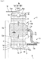
- the present invention proposes an improvement to this technology, an embodiment of which is shown in figures 6 to 8 .
- the 60' reducer figures 6 to 8 includes all the characteristics described above in relation to the figure 3 , 4 and 5 insofar as they are not contrary or do not contradict the following.
- the references used in the figures 6 to 8 and already used in figure 3 , 4 and 5 therefore designate identical or similar elements.
- the satellite 80 is of the double-stage meshing type and comprises a tubular sleeve 86 connected by a veil 88 to a first external toothing 82, the sleeve 86 being itself equipped with a second toothing 84.
- the first toothing 82 has an average diameter D1 and meshes with the sun gear 70
- the second toothing 84 has an average diameter D2, different from D1 and in particular less than D1, and meshes with the ring gear 90.
- the average diameters are measured from the Y axis of each satellite 80 and represents the average between the maximum diameter and the minimum diameter of a toothing of this satellite.
- the toothing 84 is separated into two series of teeth 84d1, 84d2, here in chevron, which are located respectively on the axial ends of the sleeve 86.
- the toothing 82 comprises two series of teeth 82d1, 82d2, here also in chevron, which are located at the outer periphery of the web 88 and which are separated from each other by an annular groove 89 emerging radially outwards with respect to the Y axis.
- the toothing 82 is crossed in its middle by the plane H which passes through the groove 89, the teeth 82d1, 82d2 therefore being arranged on either side of the plane H.
- the teeth 84d1, 84d2 are also arranged symmetrically with respect to the plane H (cf. figure 7 ).
- Each of the satellites 80 is guided in rotation by two hydrodynamic bearings 81' which are formed by a cylindrical body 81a which passes through the satellite 80, and in particular its sleeve 86, and which is configured to form two oil films H1, H2 of guidance inside the satellite 80.
- the following description relates to a satellite 80 and its hydrodynamic guide bearings 81', but it is understood that it applies to all the satellites 80 and hydrodynamic bearings 81' of the reducer 60' .
- the body 81a extends along the Y axis and comprises at its longitudinal ends extensions 81b housed in orifices forming seats of the planet carrier 100.
- the body 81a is generally tubular and comprises an internal bore 81c for the circulation of oil which communicates with ducts 81d for supplying oil to external cylindrical surfaces 81e of the body with a view to the formation of the two films of oil H1, H2 between these surfaces 81e and internal cylindrical surfaces 80a of the satellite 80.
- Surfaces 81e are axially distanced from each other and separated from each other by an outer cylindrical surface 81f. As seen best at figure 8 , the surface 81f has a diameter D4 which is less than the diameter D3 of the surfaces 81e.
- the surface 81f has an extent or axial dimension L1 which is equal to the extent or axial dimension of the first toothing 82 of the satellite 80. This surface 81f is therefore bounded by two planes P1, P2 perpendicular to the axis Y and therefore parallel between them and in the plane H, which respectively pass through the axial ends of the first toothing 82.
- Each of the surfaces 81e has an extent or axial dimension L2 which is equal to the extent or axial dimension of a series of teeth 84d1, 84d2 of the second toothing 84 of the satellite 80.
- Each surface 81e is bounded by one of the planes P1, P2 and by another plane P3, P4 perpendicular to the Y axis and passing through a free axial end of the satellite 80.
- the surface 81f extends inside and along the first toothing 82, and that the surfaces 81e extend respectively along and inside the series of teeth 84d1, 84d2 of the second toothing 84.
- Several conduits 81d can lead to each surface 81e.
- the surfaces 80a of each satellite 80 are separated from each other by an internal cylindrical surface 80b.
- the surfaces 80a and 80b have substantially the same diameter D5.
- Surface 80b has an extent or axial dimension L1 and therefore the same extent as surface 81f.
- Each of the surfaces 80a has an extent or axial dimension L2 and therefore the same extent as a surface 81e.
- the surface 81f extends inside and along the surface 80b, and that the surfaces 80a respectively extend along and inside the surfaces 81e.
- each satellite 80 comprises openings 92 for the passage of oil at the level of the sleeve 86, and more particularly in the aforementioned planes P1 and P2.
- a first annular row of apertures 92 extends radially inward at the axial ends of the surfaces 80b, 81f, and a second annular row of apertures 92 opens radially inward at the opposite axial ends of these surfaces 80b , 81f.
- the arrows of figures 6 to 8 show the circulation of oil in the body 81 of a satellite 80.
- Oil is injected into the bore 81c of the body 81 and passes through the ducts 81d to form oil films H1, H2 between the surfaces 80b, 81f. Some of this oil escapes from the side of the H-plane and is then mainly discharged radially outward through the openings 92. The rest of the oil is discharged from the opposite side, radially outward at the planes P3 and P4.
Landscapes
- Engineering & Computer Science (AREA)
- General Engineering & Computer Science (AREA)
- Mechanical Engineering (AREA)
- Chemical & Material Sciences (AREA)
- Combustion & Propulsion (AREA)
- Retarders (AREA)
- General Details Of Gearings (AREA)
- Oil, Petroleum & Natural Gas (AREA)
Applications Claiming Priority (1)
| Application Number | Priority Date | Filing Date | Title |
|---|---|---|---|
| FR2011581A FR3116096B1 (fr) | 2020-11-12 | 2020-11-12 | Reducteur mecanique de turbomachine d’aeronef |
Publications (2)
| Publication Number | Publication Date |
|---|---|
| EP4001619A1 true EP4001619A1 (de) | 2022-05-25 |
| EP4001619B1 EP4001619B1 (de) | 2023-06-21 |
Family
ID=74045885
Family Applications (1)
| Application Number | Title | Priority Date | Filing Date |
|---|---|---|---|
| EP21206788.8A Active EP4001619B1 (de) | 2020-11-12 | 2021-11-05 | Mechanisches getriebe einer luftfahrzeug-turbomaschine |
Country Status (4)
| Country | Link |
|---|---|
| US (1) | US11739829B2 (de) |
| EP (1) | EP4001619B1 (de) |
| CN (1) | CN114483933A (de) |
| FR (1) | FR3116096B1 (de) |
Cited By (3)
| Publication number | Priority date | Publication date | Assignee | Title |
|---|---|---|---|---|
| EP4339097A1 (de) | 2022-09-16 | 2024-03-20 | Safran Transmission Systems | Vorrichtung zum antrieb mindestens eines rades eines flugzeugfahrwerks |
| FR3153867A1 (fr) * | 2023-10-10 | 2025-04-11 | Safran Transmission Systems | Reducteur mecanique de turbomachine d’aeronef |
| WO2025176957A1 (fr) * | 2024-02-23 | 2025-08-28 | Safran Transmission Systems | Dispositif d'alimentation en huile pour un reducteur mecanique d'une turbomachine d'aeronef |
Families Citing this family (12)
| Publication number | Priority date | Publication date | Assignee | Title |
|---|---|---|---|---|
| FR3115340B1 (fr) * | 2020-10-16 | 2022-09-16 | Safran Aircraft Engines | Système propulsif aéronautique ayant un rendement propulsif amélioré |
| FR3139602A1 (fr) * | 2022-09-13 | 2024-03-15 | Safran Transmission Systems | Turbomachine d’aeronef a reducteur mecanique |
| US12312091B2 (en) | 2022-10-06 | 2025-05-27 | Archer Aviation Inc. | Systems and methods for improved gearboxes for evtol aircraft |
| US12227300B2 (en) | 2022-10-06 | 2025-02-18 | Archer Aviation Inc. | Systems and methods for oil maintenance in gearboxes for eVTOL aircraft |
| US11787551B1 (en) | 2022-10-06 | 2023-10-17 | Archer Aviation, Inc. | Vertical takeoff and landing aircraft electric engine configuration |
| US12429000B2 (en) * | 2023-08-08 | 2025-09-30 | Rtx Corporation | Elongated journal bearing for high gear ratio epicyclic fan drive gear system |
| FR3157913A1 (fr) | 2023-12-27 | 2025-07-04 | Safran Transmission Systems | Mecanisme de reduction pour système propulsif aeronautique |
| FR3157911B1 (fr) | 2023-12-27 | 2025-11-21 | Safran Trans Systems | Mecanisme de reduction pour système propulsif aeronautique |
| FR3157912A1 (fr) | 2023-12-27 | 2025-07-04 | Safran Transmission Systems | Mecanisme de reduction pour système propulsif aeronautique |
| FR3157910B1 (fr) | 2023-12-27 | 2025-11-21 | Safran Trans Systems | Mecanisme de reduction pour système propulsif aeronautique |
| FR3157914B1 (fr) | 2023-12-27 | 2025-11-21 | Safran Trans Systems | Mecanisme de reduction pour système propulsif aeronautique |
| US12152667B1 (en) * | 2024-03-08 | 2024-11-26 | Schaeffler Technologies AG & Co. KG | Gearbox cover with planetary carrier |
Citations (6)
| Publication number | Priority date | Publication date | Assignee | Title |
|---|---|---|---|---|
| WO2010092263A1 (fr) | 2009-02-16 | 2010-08-19 | Snecma | Lubrification et refroidissement d'un reducteur a train d'engrenages epicycloïdal |
| FR2987416A1 (fr) | 2012-02-23 | 2013-08-30 | Snecma | Dispositif de lubrification d'un reducteur epicycloidal. |
| FR3008462A1 (fr) | 2013-07-10 | 2015-01-16 | Hispano Suiza Sa | Integration d'un train d'engrenages dans un voile de pignon de boitier d'entrainement pour turbomachine |
| FR3041054A1 (fr) | 2015-09-15 | 2017-03-17 | Hispano-Suiza | Dispositif d'alimentation en huile pour un reducteur a train epicycloidal. |
| DE102018009737A1 (de) | 2018-12-13 | 2020-06-18 | Miba Gleitlager Austria Gmbh | Windkraftanlagengetriebe mit zumindest einem Gleitlager |
| EP3726031A1 (de) | 2019-04-16 | 2020-10-21 | Safran Transmission Systems | Mechanisches reduktionsgetriebe für luftfahrzeug-turbotriebwerk |
Family Cites Families (6)
| Publication number | Priority date | Publication date | Assignee | Title |
|---|---|---|---|---|
| US4271928A (en) * | 1978-07-11 | 1981-06-09 | Rolls-Royce Limited | Lubricant supply device |
| CN205715582U (zh) * | 2016-04-13 | 2016-11-23 | 南京高速齿轮制造有限公司 | 用于风电设备的行星齿轮变速器 |
| CN107299966B (zh) * | 2016-04-15 | 2019-09-24 | 南京高速齿轮制造有限公司 | 一种行星齿轮变速器 |
| GB201611605D0 (en) * | 2016-07-04 | 2016-08-17 | Rolls-Royce Ltd | A Gas Turbine Engine |
| CN109667918A (zh) * | 2017-10-13 | 2019-04-23 | 南京高速齿轮制造有限公司 | 一种行星齿轮变速器以及风力发电设备 |
| CN110081150B (zh) * | 2019-05-14 | 2024-03-01 | 南京高速齿轮制造有限公司 | 风电齿轮箱及其行星轮轴承润滑固定结构 |
-
2020
- 2020-11-12 FR FR2011581A patent/FR3116096B1/fr active Active
-
2021
- 2021-11-05 EP EP21206788.8A patent/EP4001619B1/de active Active
- 2021-11-09 US US17/454,118 patent/US11739829B2/en active Active
- 2021-11-12 CN CN202111340489.3A patent/CN114483933A/zh active Pending
Patent Citations (6)
| Publication number | Priority date | Publication date | Assignee | Title |
|---|---|---|---|---|
| WO2010092263A1 (fr) | 2009-02-16 | 2010-08-19 | Snecma | Lubrification et refroidissement d'un reducteur a train d'engrenages epicycloïdal |
| FR2987416A1 (fr) | 2012-02-23 | 2013-08-30 | Snecma | Dispositif de lubrification d'un reducteur epicycloidal. |
| FR3008462A1 (fr) | 2013-07-10 | 2015-01-16 | Hispano Suiza Sa | Integration d'un train d'engrenages dans un voile de pignon de boitier d'entrainement pour turbomachine |
| FR3041054A1 (fr) | 2015-09-15 | 2017-03-17 | Hispano-Suiza | Dispositif d'alimentation en huile pour un reducteur a train epicycloidal. |
| DE102018009737A1 (de) | 2018-12-13 | 2020-06-18 | Miba Gleitlager Austria Gmbh | Windkraftanlagengetriebe mit zumindest einem Gleitlager |
| EP3726031A1 (de) | 2019-04-16 | 2020-10-21 | Safran Transmission Systems | Mechanisches reduktionsgetriebe für luftfahrzeug-turbotriebwerk |
Cited By (7)
| Publication number | Priority date | Publication date | Assignee | Title |
|---|---|---|---|---|
| EP4339097A1 (de) | 2022-09-16 | 2024-03-20 | Safran Transmission Systems | Vorrichtung zum antrieb mindestens eines rades eines flugzeugfahrwerks |
| FR3139798A1 (fr) * | 2022-09-16 | 2024-03-22 | Safran Transmission Systems | Dispositif d’entrainement d’au moins une roue d’un train d’atterrissage d’aeronef |
| US12448118B2 (en) | 2022-09-16 | 2025-10-21 | Safran Transmission Systems | Device for driving at least one wheel of an aircraft landing gear |
| FR3153867A1 (fr) * | 2023-10-10 | 2025-04-11 | Safran Transmission Systems | Reducteur mecanique de turbomachine d’aeronef |
| WO2025078751A1 (fr) | 2023-10-10 | 2025-04-17 | Safran Transmission Systems | Reducteur mecanique de turbomachine d'aeronef |
| WO2025176957A1 (fr) * | 2024-02-23 | 2025-08-28 | Safran Transmission Systems | Dispositif d'alimentation en huile pour un reducteur mecanique d'une turbomachine d'aeronef |
| FR3159631A1 (fr) * | 2024-02-23 | 2025-08-29 | Safran Transmission Systems | Dispositif d’alimentation en huile pour un reducteur mecanique d’une turbomachine d’aeronef |
Also Published As
| Publication number | Publication date |
|---|---|
| FR3116096B1 (fr) | 2023-06-30 |
| US11739829B2 (en) | 2023-08-29 |
| FR3116096A1 (fr) | 2022-05-13 |
| EP4001619B1 (de) | 2023-06-21 |
| US20220145806A1 (en) | 2022-05-12 |
| CN114483933A (zh) | 2022-05-13 |
Similar Documents
| Publication | Publication Date | Title |
|---|---|---|
| EP4001619B1 (de) | Mechanisches getriebe einer luftfahrzeug-turbomaschine | |
| EP3726031B1 (de) | Mechanisches reduktionsgetriebe für luftfahrzeug-turbotriebwerk | |
| EP3922886B1 (de) | Mechanisches reduktionsgetriebe für turbotriebwerk eines luftfahrzeugs | |
| EP3892895B1 (de) | Mechanisches reduktionsgetriebe für turbotriebwerk eines luftfahrzeugs | |
| EP3922831B1 (de) | Mechanisches reduktionsgetriebe für turbotriebwerk eines luftfahrzeugs | |
| EP3995681B1 (de) | Mechanisches reduktionsgetriebe für turbotriebwerk eines luftfahrzeugs | |
| EP4303468B1 (de) | Sonnenrad für ein reduktionsgetriebe eines turbotriebwerks eines luftfahrzeugs | |
| EP4151846A1 (de) | Turbomaschine eines luftfahrzeugs | |
| EP4336070B1 (de) | Antriebsanordnung für ein mechanisches reduktionsgetriebe einer turbomaschine eines flugzeugs | |
| EP4265940B1 (de) | Mechanisches reduktionsgetriebe für eine flugzeugturbomaschine | |
| EP4242489B1 (de) | Mechanisches reduktionsgetriebe für flugzeugturbomaschine | |
| WO2025078751A1 (fr) | Reducteur mecanique de turbomachine d'aeronef | |
| EP4339098B1 (de) | Antriebsvorrichtung für mindestens ein rad eines flugzeugfahrwerks | |
| EP4471295B1 (de) | Solar für ein mechanisches reduktionsgetriebe eines turbotriebwerks eines luftfahrzeugs | |
| EP4093992B1 (de) | Planetenträger für ein mechanisches untersetzungsgetriebe einer flugzeugturbomaschine | |
| WO2024261427A1 (fr) | Turbomachine d'aeronef a double helice de propulsion | |
| FR3139602A1 (fr) | Turbomachine d’aeronef a reducteur mecanique | |
| WO2026003460A1 (fr) | Porte-satellites pour un reducteur mecanique de turbomachine d'aeronef | |
| FR3161413A1 (fr) | Dispositif d’entrainement d’au moins une roue d’un train d’atterrissage d’aeronef | |
| EP4375523A1 (de) | Gleitlager für einen satelliten eines mechanischen reduktionsgetriebes eines turbotriebwerks eines luftfahrzeugs |
Legal Events
| Date | Code | Title | Description |
|---|---|---|---|
| PUAI | Public reference made under article 153(3) epc to a published international application that has entered the european phase |
Free format text: ORIGINAL CODE: 0009012 |
|
| STAA | Information on the status of an ep patent application or granted ep patent |
Free format text: STATUS: REQUEST FOR EXAMINATION WAS MADE |
|
| 17P | Request for examination filed |
Effective date: 20211105 |
|
| AK | Designated contracting states |
Kind code of ref document: A1 Designated state(s): AL AT BE BG CH CY CZ DE DK EE ES FI FR GB GR HR HU IE IS IT LI LT LU LV MC MK MT NL NO PL PT RO RS SE SI SK SM TR |
|
| RIC1 | Information provided on ipc code assigned before grant |
Ipc: F16H 57/08 20060101ALN20230125BHEP Ipc: F16H 57/04 20060101ALI20230125BHEP Ipc: F16H 1/28 20060101ALI20230125BHEP Ipc: F02C 7/36 20060101AFI20230125BHEP |
|
| GRAP | Despatch of communication of intention to grant a patent |
Free format text: ORIGINAL CODE: EPIDOSNIGR1 |
|
| STAA | Information on the status of an ep patent application or granted ep patent |
Free format text: STATUS: GRANT OF PATENT IS INTENDED |
|
| INTG | Intention to grant announced |
Effective date: 20230310 |
|
| GRAS | Grant fee paid |
Free format text: ORIGINAL CODE: EPIDOSNIGR3 |
|
| GRAA | (expected) grant |
Free format text: ORIGINAL CODE: 0009210 |
|
| STAA | Information on the status of an ep patent application or granted ep patent |
Free format text: STATUS: THE PATENT HAS BEEN GRANTED |
|
| AK | Designated contracting states |
Kind code of ref document: B1 Designated state(s): AL AT BE BG CH CY CZ DE DK EE ES FI FR GB GR HR HU IE IS IT LI LT LU LV MC MK MT NL NO PL PT RO RS SE SI SK SM TR |
|
| REG | Reference to a national code |
Ref country code: CH Ref legal event code: EP |
|
| REG | Reference to a national code |
Ref country code: DE Ref legal event code: R096 Ref document number: 602021003029 Country of ref document: DE |
|
| REG | Reference to a national code |
Ref country code: AT Ref legal event code: REF Ref document number: 1581051 Country of ref document: AT Kind code of ref document: T Effective date: 20230715 |
|
| REG | Reference to a national code |
Ref country code: IE Ref legal event code: FG4D Free format text: LANGUAGE OF EP DOCUMENT: FRENCH |
|
| REG | Reference to a national code |
Ref country code: LT Ref legal event code: MG9D |
|
| REG | Reference to a national code |
Ref country code: NL Ref legal event code: MP Effective date: 20230621 |
|
| PG25 | Lapsed in a contracting state [announced via postgrant information from national office to epo] |
Ref country code: SE Free format text: LAPSE BECAUSE OF FAILURE TO SUBMIT A TRANSLATION OF THE DESCRIPTION OR TO PAY THE FEE WITHIN THE PRESCRIBED TIME-LIMIT Effective date: 20230621 Ref country code: NO Free format text: LAPSE BECAUSE OF FAILURE TO SUBMIT A TRANSLATION OF THE DESCRIPTION OR TO PAY THE FEE WITHIN THE PRESCRIBED TIME-LIMIT Effective date: 20230921 |
|
| REG | Reference to a national code |
Ref country code: AT Ref legal event code: MK05 Ref document number: 1581051 Country of ref document: AT Kind code of ref document: T Effective date: 20230621 |
|
| PG25 | Lapsed in a contracting state [announced via postgrant information from national office to epo] |
Ref country code: RS Free format text: LAPSE BECAUSE OF FAILURE TO SUBMIT A TRANSLATION OF THE DESCRIPTION OR TO PAY THE FEE WITHIN THE PRESCRIBED TIME-LIMIT Effective date: 20230621 Ref country code: NL Free format text: LAPSE BECAUSE OF FAILURE TO SUBMIT A TRANSLATION OF THE DESCRIPTION OR TO PAY THE FEE WITHIN THE PRESCRIBED TIME-LIMIT Effective date: 20230621 Ref country code: LV Free format text: LAPSE BECAUSE OF FAILURE TO SUBMIT A TRANSLATION OF THE DESCRIPTION OR TO PAY THE FEE WITHIN THE PRESCRIBED TIME-LIMIT Effective date: 20230621 Ref country code: LT Free format text: LAPSE BECAUSE OF FAILURE TO SUBMIT A TRANSLATION OF THE DESCRIPTION OR TO PAY THE FEE WITHIN THE PRESCRIBED TIME-LIMIT Effective date: 20230621 Ref country code: HR Free format text: LAPSE BECAUSE OF FAILURE TO SUBMIT A TRANSLATION OF THE DESCRIPTION OR TO PAY THE FEE WITHIN THE PRESCRIBED TIME-LIMIT Effective date: 20230621 Ref country code: GR Free format text: LAPSE BECAUSE OF FAILURE TO SUBMIT A TRANSLATION OF THE DESCRIPTION OR TO PAY THE FEE WITHIN THE PRESCRIBED TIME-LIMIT Effective date: 20230922 |
|
| PG25 | Lapsed in a contracting state [announced via postgrant information from national office to epo] |
Ref country code: FI Free format text: LAPSE BECAUSE OF FAILURE TO SUBMIT A TRANSLATION OF THE DESCRIPTION OR TO PAY THE FEE WITHIN THE PRESCRIBED TIME-LIMIT Effective date: 20230621 |
|
| PG25 | Lapsed in a contracting state [announced via postgrant information from national office to epo] |
Ref country code: SK Free format text: LAPSE BECAUSE OF FAILURE TO SUBMIT A TRANSLATION OF THE DESCRIPTION OR TO PAY THE FEE WITHIN THE PRESCRIBED TIME-LIMIT Effective date: 20230621 |
|
| PG25 | Lapsed in a contracting state [announced via postgrant information from national office to epo] |
Ref country code: ES Free format text: LAPSE BECAUSE OF FAILURE TO SUBMIT A TRANSLATION OF THE DESCRIPTION OR TO PAY THE FEE WITHIN THE PRESCRIBED TIME-LIMIT Effective date: 20230621 |
|
| PG25 | Lapsed in a contracting state [announced via postgrant information from national office to epo] |
Ref country code: IS Free format text: LAPSE BECAUSE OF FAILURE TO SUBMIT A TRANSLATION OF THE DESCRIPTION OR TO PAY THE FEE WITHIN THE PRESCRIBED TIME-LIMIT Effective date: 20231021 |
|
| PG25 | Lapsed in a contracting state [announced via postgrant information from national office to epo] |
Ref country code: SM Free format text: LAPSE BECAUSE OF FAILURE TO SUBMIT A TRANSLATION OF THE DESCRIPTION OR TO PAY THE FEE WITHIN THE PRESCRIBED TIME-LIMIT Effective date: 20230621 Ref country code: SK Free format text: LAPSE BECAUSE OF FAILURE TO SUBMIT A TRANSLATION OF THE DESCRIPTION OR TO PAY THE FEE WITHIN THE PRESCRIBED TIME-LIMIT Effective date: 20230621 Ref country code: RO Free format text: LAPSE BECAUSE OF FAILURE TO SUBMIT A TRANSLATION OF THE DESCRIPTION OR TO PAY THE FEE WITHIN THE PRESCRIBED TIME-LIMIT Effective date: 20230621 Ref country code: PT Free format text: LAPSE BECAUSE OF FAILURE TO SUBMIT A TRANSLATION OF THE DESCRIPTION OR TO PAY THE FEE WITHIN THE PRESCRIBED TIME-LIMIT Effective date: 20231023 Ref country code: IS Free format text: LAPSE BECAUSE OF FAILURE TO SUBMIT A TRANSLATION OF THE DESCRIPTION OR TO PAY THE FEE WITHIN THE PRESCRIBED TIME-LIMIT Effective date: 20231021 Ref country code: ES Free format text: LAPSE BECAUSE OF FAILURE TO SUBMIT A TRANSLATION OF THE DESCRIPTION OR TO PAY THE FEE WITHIN THE PRESCRIBED TIME-LIMIT Effective date: 20230621 Ref country code: EE Free format text: LAPSE BECAUSE OF FAILURE TO SUBMIT A TRANSLATION OF THE DESCRIPTION OR TO PAY THE FEE WITHIN THE PRESCRIBED TIME-LIMIT Effective date: 20230621 Ref country code: CZ Free format text: LAPSE BECAUSE OF FAILURE TO SUBMIT A TRANSLATION OF THE DESCRIPTION OR TO PAY THE FEE WITHIN THE PRESCRIBED TIME-LIMIT Effective date: 20230621 Ref country code: AT Free format text: LAPSE BECAUSE OF FAILURE TO SUBMIT A TRANSLATION OF THE DESCRIPTION OR TO PAY THE FEE WITHIN THE PRESCRIBED TIME-LIMIT Effective date: 20230621 |
|
| PG25 | Lapsed in a contracting state [announced via postgrant information from national office to epo] |
Ref country code: PL Free format text: LAPSE BECAUSE OF FAILURE TO SUBMIT A TRANSLATION OF THE DESCRIPTION OR TO PAY THE FEE WITHIN THE PRESCRIBED TIME-LIMIT Effective date: 20230621 |
|
| REG | Reference to a national code |
Ref country code: DE Ref legal event code: R097 Ref document number: 602021003029 Country of ref document: DE |
|
| PLBE | No opposition filed within time limit |
Free format text: ORIGINAL CODE: 0009261 |
|
| STAA | Information on the status of an ep patent application or granted ep patent |
Free format text: STATUS: NO OPPOSITION FILED WITHIN TIME LIMIT |
|
| PG25 | Lapsed in a contracting state [announced via postgrant information from national office to epo] |
Ref country code: DK Free format text: LAPSE BECAUSE OF FAILURE TO SUBMIT A TRANSLATION OF THE DESCRIPTION OR TO PAY THE FEE WITHIN THE PRESCRIBED TIME-LIMIT Effective date: 20230621 |
|
| PG25 | Lapsed in a contracting state [announced via postgrant information from national office to epo] |
Ref country code: SI Free format text: LAPSE BECAUSE OF FAILURE TO SUBMIT A TRANSLATION OF THE DESCRIPTION OR TO PAY THE FEE WITHIN THE PRESCRIBED TIME-LIMIT Effective date: 20230621 |
|
| 26N | No opposition filed |
Effective date: 20240322 |
|
| PG25 | Lapsed in a contracting state [announced via postgrant information from national office to epo] |
Ref country code: SI Free format text: LAPSE BECAUSE OF FAILURE TO SUBMIT A TRANSLATION OF THE DESCRIPTION OR TO PAY THE FEE WITHIN THE PRESCRIBED TIME-LIMIT Effective date: 20230621 Ref country code: IT Free format text: LAPSE BECAUSE OF FAILURE TO SUBMIT A TRANSLATION OF THE DESCRIPTION OR TO PAY THE FEE WITHIN THE PRESCRIBED TIME-LIMIT Effective date: 20230621 |
|
| PG25 | Lapsed in a contracting state [announced via postgrant information from national office to epo] |
Ref country code: MC Free format text: LAPSE BECAUSE OF FAILURE TO SUBMIT A TRANSLATION OF THE DESCRIPTION OR TO PAY THE FEE WITHIN THE PRESCRIBED TIME-LIMIT Effective date: 20230621 |
|
| PG25 | Lapsed in a contracting state [announced via postgrant information from national office to epo] |
Ref country code: LU Free format text: LAPSE BECAUSE OF NON-PAYMENT OF DUE FEES Effective date: 20231105 |
|
| PG25 | Lapsed in a contracting state [announced via postgrant information from national office to epo] |
Ref country code: MC Free format text: LAPSE BECAUSE OF FAILURE TO SUBMIT A TRANSLATION OF THE DESCRIPTION OR TO PAY THE FEE WITHIN THE PRESCRIBED TIME-LIMIT Effective date: 20230621 Ref country code: LU Free format text: LAPSE BECAUSE OF NON-PAYMENT OF DUE FEES Effective date: 20231105 |
|
| REG | Reference to a national code |
Ref country code: BE Ref legal event code: MM Effective date: 20231130 |
|
| REG | Reference to a national code |
Ref country code: IE Ref legal event code: MM4A |
|
| PG25 | Lapsed in a contracting state [announced via postgrant information from national office to epo] |
Ref country code: IE Free format text: LAPSE BECAUSE OF NON-PAYMENT OF DUE FEES Effective date: 20231105 |
|
| PG25 | Lapsed in a contracting state [announced via postgrant information from national office to epo] |
Ref country code: BE Free format text: LAPSE BECAUSE OF NON-PAYMENT OF DUE FEES Effective date: 20231130 |
|
| PG25 | Lapsed in a contracting state [announced via postgrant information from national office to epo] |
Ref country code: IE Free format text: LAPSE BECAUSE OF NON-PAYMENT OF DUE FEES Effective date: 20231105 Ref country code: BE Free format text: LAPSE BECAUSE OF NON-PAYMENT OF DUE FEES Effective date: 20231130 |
|
| PG25 | Lapsed in a contracting state [announced via postgrant information from national office to epo] |
Ref country code: BG Free format text: LAPSE BECAUSE OF FAILURE TO SUBMIT A TRANSLATION OF THE DESCRIPTION OR TO PAY THE FEE WITHIN THE PRESCRIBED TIME-LIMIT Effective date: 20230621 |
|
| PG25 | Lapsed in a contracting state [announced via postgrant information from national office to epo] |
Ref country code: BG Free format text: LAPSE BECAUSE OF FAILURE TO SUBMIT A TRANSLATION OF THE DESCRIPTION OR TO PAY THE FEE WITHIN THE PRESCRIBED TIME-LIMIT Effective date: 20230621 |
|
| REG | Reference to a national code |
Ref country code: CH Ref legal event code: PL |
|
| REG | Reference to a national code |
Ref country code: CH Ref legal event code: PL |
|
| PG25 | Lapsed in a contracting state [announced via postgrant information from national office to epo] |
Ref country code: CH Free format text: LAPSE BECAUSE OF NON-PAYMENT OF DUE FEES Effective date: 20241130 |
|
| PG25 | Lapsed in a contracting state [announced via postgrant information from national office to epo] |
Ref country code: CY Free format text: LAPSE BECAUSE OF FAILURE TO SUBMIT A TRANSLATION OF THE DESCRIPTION OR TO PAY THE FEE WITHIN THE PRESCRIBED TIME-LIMIT; INVALID AB INITIO Effective date: 20211105 |
|
| PG25 | Lapsed in a contracting state [announced via postgrant information from national office to epo] |
Ref country code: TR Free format text: LAPSE BECAUSE OF FAILURE TO SUBMIT A TRANSLATION OF THE DESCRIPTION OR TO PAY THE FEE WITHIN THE PRESCRIBED TIME-LIMIT Effective date: 20230621 |
|
| PGFP | Annual fee paid to national office [announced via postgrant information from national office to epo] |
Ref country code: DE Payment date: 20251118 Year of fee payment: 5 |
|
| PGFP | Annual fee paid to national office [announced via postgrant information from national office to epo] |
Ref country code: GB Payment date: 20251125 Year of fee payment: 5 |
|
| PGFP | Annual fee paid to national office [announced via postgrant information from national office to epo] |
Ref country code: FR Payment date: 20251125 Year of fee payment: 5 |
|
| PG25 | Lapsed in a contracting state [announced via postgrant information from national office to epo] |
Ref country code: HU Free format text: LAPSE BECAUSE OF FAILURE TO SUBMIT A TRANSLATION OF THE DESCRIPTION OR TO PAY THE FEE WITHIN THE PRESCRIBED TIME-LIMIT; INVALID AB INITIO Effective date: 20211105 |