EP4001645A1 - Propulseur bidirectionnel à plasma d'ondes pour engin spatial - Google Patents
Propulseur bidirectionnel à plasma d'ondes pour engin spatial Download PDFInfo
- Publication number
- EP4001645A1 EP4001645A1 EP21179090.2A EP21179090A EP4001645A1 EP 4001645 A1 EP4001645 A1 EP 4001645A1 EP 21179090 A EP21179090 A EP 21179090A EP 4001645 A1 EP4001645 A1 EP 4001645A1
- Authority
- EP
- European Patent Office
- Prior art keywords
- discharge chamber
- gas discharge
- thruster
- spacecraft
- plasma
- Prior art date
- Legal status (The legal status is an assumption and is not a legal conclusion. Google has not performed a legal analysis and makes no representation as to the accuracy of the status listed.)
- Withdrawn
Links
- 239000003380 propellant Substances 0.000 claims abstract description 29
- 230000005670 electromagnetic radiation Effects 0.000 claims abstract description 15
- 239000013598 vector Substances 0.000 claims abstract description 12
- 238000011144 upstream manufacturing Methods 0.000 claims abstract description 8
- 239000003989 dielectric material Substances 0.000 claims abstract description 5
- 230000001276 controlling effect Effects 0.000 claims description 6
- 230000005540 biological transmission Effects 0.000 claims description 5
- 230000001133 acceleration Effects 0.000 abstract description 15
- 230000008878 coupling Effects 0.000 abstract description 10
- 238000010168 coupling process Methods 0.000 abstract description 10
- 238000005859 coupling reaction Methods 0.000 abstract description 10
- 230000008030 elimination Effects 0.000 abstract description 8
- 238000003379 elimination reaction Methods 0.000 abstract description 8
- 230000003071 parasitic effect Effects 0.000 abstract description 8
- 230000009467 reduction Effects 0.000 abstract description 6
- 238000012423 maintenance Methods 0.000 abstract description 5
- 238000009434 installation Methods 0.000 abstract description 2
- 239000000126 substance Substances 0.000 abstract description 2
- 230000001419 dependent effect Effects 0.000 abstract 1
- 210000002381 plasma Anatomy 0.000 description 92
- 238000000034 method Methods 0.000 description 10
- 230000007246 mechanism Effects 0.000 description 9
- 230000005672 electromagnetic field Effects 0.000 description 8
- 230000015572 biosynthetic process Effects 0.000 description 7
- 239000002245 particle Substances 0.000 description 7
- 230000008569 process Effects 0.000 description 7
- 238000004544 sputter deposition Methods 0.000 description 7
- BSYNRYMUTXBXSQ-UHFFFAOYSA-N Aspirin Chemical compound CC(=O)OC1=CC=CC=C1C(O)=O BSYNRYMUTXBXSQ-UHFFFAOYSA-N 0.000 description 6
- 229910052751 metal Inorganic materials 0.000 description 6
- 238000012546 transfer Methods 0.000 description 6
- 238000006243 chemical reaction Methods 0.000 description 5
- 238000010438 heat treatment Methods 0.000 description 5
- 150000002500 ions Chemical class 0.000 description 5
- 239000002184 metal Substances 0.000 description 5
- 230000003993 interaction Effects 0.000 description 4
- 230000008859 change Effects 0.000 description 3
- 230000000694 effects Effects 0.000 description 3
- 230000005684 electric field Effects 0.000 description 3
- XEEYBQQBJWHFJM-UHFFFAOYSA-N Iron Chemical compound [Fe] XEEYBQQBJWHFJM-UHFFFAOYSA-N 0.000 description 2
- 238000004458 analytical method Methods 0.000 description 2
- 230000006378 damage Effects 0.000 description 2
- 238000000151 deposition Methods 0.000 description 2
- 230000008021 deposition Effects 0.000 description 2
- 238000009792 diffusion process Methods 0.000 description 2
- 238000002474 experimental method Methods 0.000 description 2
- 239000000463 material Substances 0.000 description 2
- 230000010355 oscillation Effects 0.000 description 2
- 238000000926 separation method Methods 0.000 description 2
- RYGMFSIKBFXOCR-UHFFFAOYSA-N Copper Chemical compound [Cu] RYGMFSIKBFXOCR-UHFFFAOYSA-N 0.000 description 1
- VYPSYNLAJGMNEJ-UHFFFAOYSA-N Silicium dioxide Chemical compound O=[Si]=O VYPSYNLAJGMNEJ-UHFFFAOYSA-N 0.000 description 1
- 229910000831 Steel Inorganic materials 0.000 description 1
- RTAQQCXQSZGOHL-UHFFFAOYSA-N Titanium Chemical compound [Ti] RTAQQCXQSZGOHL-UHFFFAOYSA-N 0.000 description 1
- 229910052782 aluminium Inorganic materials 0.000 description 1
- XAGFODPZIPBFFR-UHFFFAOYSA-N aluminium Chemical compound [Al] XAGFODPZIPBFFR-UHFFFAOYSA-N 0.000 description 1
- PNEYBMLMFCGWSK-UHFFFAOYSA-N aluminium oxide Inorganic materials [O-2].[O-2].[O-2].[Al+3].[Al+3] PNEYBMLMFCGWSK-UHFFFAOYSA-N 0.000 description 1
- 230000008901 benefit Effects 0.000 description 1
- 229910052802 copper Inorganic materials 0.000 description 1
- 239000010949 copper Substances 0.000 description 1
- 229910052593 corundum Inorganic materials 0.000 description 1
- 238000013461 design Methods 0.000 description 1
- 238000011161 development Methods 0.000 description 1
- 230000018109 developmental process Effects 0.000 description 1
- 238000010586 diagram Methods 0.000 description 1
- 239000003574 free electron Substances 0.000 description 1
- 230000006870 function Effects 0.000 description 1
- 230000004927 fusion Effects 0.000 description 1
- 238000009616 inductively coupled plasma Methods 0.000 description 1
- 238000000752 ionisation method Methods 0.000 description 1
- 229910052742 iron Inorganic materials 0.000 description 1
- 150000002739 metals Chemical class 0.000 description 1
- 239000003058 plasma substitute Substances 0.000 description 1
- 230000001681 protective effect Effects 0.000 description 1
- 230000006798 recombination Effects 0.000 description 1
- 238000005215 recombination Methods 0.000 description 1
- 238000012552 review Methods 0.000 description 1
- 239000000523 sample Substances 0.000 description 1
- 239000010959 steel Substances 0.000 description 1
- 238000013517 stratification Methods 0.000 description 1
- 230000001629 suppression Effects 0.000 description 1
- 239000010936 titanium Substances 0.000 description 1
- 229910052719 titanium Inorganic materials 0.000 description 1
- 230000009466 transformation Effects 0.000 description 1
- 229910001845 yogo sapphire Inorganic materials 0.000 description 1
Images
Classifications
-
- F—MECHANICAL ENGINEERING; LIGHTING; HEATING; WEAPONS; BLASTING
- F03—MACHINES OR ENGINES FOR LIQUIDS; WIND, SPRING, OR WEIGHT MOTORS; PRODUCING MECHANICAL POWER OR A REACTIVE PROPULSIVE THRUST, NOT OTHERWISE PROVIDED FOR
- F03H—PRODUCING A REACTIVE PROPULSIVE THRUST, NOT OTHERWISE PROVIDED FOR
- F03H1/00—Using plasma to produce a reactive propulsive thrust
- F03H1/0081—Electromagnetic plasma thrusters
-
- F—MECHANICAL ENGINEERING; LIGHTING; HEATING; WEAPONS; BLASTING
- F03—MACHINES OR ENGINES FOR LIQUIDS; WIND, SPRING, OR WEIGHT MOTORS; PRODUCING MECHANICAL POWER OR A REACTIVE PROPULSIVE THRUST, NOT OTHERWISE PROVIDED FOR
- F03H—PRODUCING A REACTIVE PROPULSIVE THRUST, NOT OTHERWISE PROVIDED FOR
- F03H1/00—Using plasma to produce a reactive propulsive thrust
-
- F—MECHANICAL ENGINEERING; LIGHTING; HEATING; WEAPONS; BLASTING
- F03—MACHINES OR ENGINES FOR LIQUIDS; WIND, SPRING, OR WEIGHT MOTORS; PRODUCING MECHANICAL POWER OR A REACTIVE PROPULSIVE THRUST, NOT OTHERWISE PROVIDED FOR
- F03H—PRODUCING A REACTIVE PROPULSIVE THRUST, NOT OTHERWISE PROVIDED FOR
- F03H1/00—Using plasma to produce a reactive propulsive thrust
- F03H1/0006—Details applicable to different types of plasma thrusters
-
- F—MECHANICAL ENGINEERING; LIGHTING; HEATING; WEAPONS; BLASTING
- F03—MACHINES OR ENGINES FOR LIQUIDS; WIND, SPRING, OR WEIGHT MOTORS; PRODUCING MECHANICAL POWER OR A REACTIVE PROPULSIVE THRUST, NOT OTHERWISE PROVIDED FOR
- F03H—PRODUCING A REACTIVE PROPULSIVE THRUST, NOT OTHERWISE PROVIDED FOR
- F03H1/00—Using plasma to produce a reactive propulsive thrust
- F03H1/0006—Details applicable to different types of plasma thrusters
- F03H1/0012—Means for supplying the propellant
-
- F—MECHANICAL ENGINEERING; LIGHTING; HEATING; WEAPONS; BLASTING
- F03—MACHINES OR ENGINES FOR LIQUIDS; WIND, SPRING, OR WEIGHT MOTORS; PRODUCING MECHANICAL POWER OR A REACTIVE PROPULSIVE THRUST, NOT OTHERWISE PROVIDED FOR
- F03H—PRODUCING A REACTIVE PROPULSIVE THRUST, NOT OTHERWISE PROVIDED FOR
- F03H1/00—Using plasma to produce a reactive propulsive thrust
- F03H1/0093—Electro-thermal plasma thrusters, i.e. thrusters heating the particles in a plasma
-
- H—ELECTRICITY
- H05—ELECTRIC TECHNIQUES NOT OTHERWISE PROVIDED FOR
- H05H—PLASMA TECHNIQUE; PRODUCTION OF ACCELERATED ELECTRICALLY-CHARGED PARTICLES OR OF NEUTRONS; PRODUCTION OR ACCELERATION OF NEUTRAL MOLECULAR OR ATOMIC BEAMS
- H05H1/00—Generating plasma; Handling plasma
- H05H1/54—Plasma accelerators
Definitions
- the invention relates to space engineering, in particular, to electric propulsion systems (EP) with electric rocket engines with electrodeless plasma source and acceleration stage using a wide variety of substances as a propellant, designed mainly for installation onboard a spacecraft for transferring it from parking orbit to the target orbit, orbit maintenance, attitude control, altitude control, unloading attitude control systems, maneuvers between orbits, and de-orbiting.
- EP electric propulsion systems
- attitude control attitude control
- altitude control altitude control
- unloading attitude control systems maneuvers between orbits, and de-orbiting.
- the prior art discloses the More efficient RF plasma electric thruster (patent US6293090B1, published on 25.09.2001 .)
- the invention relates to plasma thrusters. It primarily consists of an RF generator, a set of radiating elements, a gas discharge chamber defining the main axis of the thruster, a magnetic system, a power source of the magnetic system, and a propellant supply system connected to a gas discharge chamber.
- the resulting thruster failure due to the deposition of the sputtered material on the external surface of the gas discharge chamber, will shield the electromagnetic radiation from the plasma generated by the radiating elements.
- the placement of the gas feedthrough at the upstream side of the gas discharge chamber will result lead to the loss of power to the process of re-ionization of recombined particles of the ionized propellant along the length of the discharge chamber. This in turn leads to a reduction of specific thrust and a specific impulse of the thruster per unit of power.
- the prior art discloses Helicon plasma electric propulsion device (patent CN104405603B, published 12.04.2017 .).
- the invention relates to plasma thrusters. It includes at least one metal ring that makes up the thruster housing: the first and second metal flanges, a helicon antenna, a gas discharge chamber, gas feedthrough, and at least two rings of magnets.
- the disadvantage of this invention is that the gas feedthrough is connected to the gas discharge chamber from one of its ends.
- the ability to use two ends of the gas-discharge chamber for the flow of plasma and the creation of thrust in this direction is lost.
- the volume, mass, and power consumption of the propulsion system increases when several such engines are placed to control many thrust axes, which makes it inefficient or impossible to use onboard the spacecraft.
- the placement of the gas feedthrough at the upstream side of the gas discharge chamber will lead to the loss of power to the process of re-ionization of recombined particles of the ionized propellant along the length of the discharge chamber, which in turn leads to a reduction of specific thrust and a specific impulse of the thruster per unit of power.
- the use of the Helicon antenna without protective dielectric rings will result in spurious capacitively coupled discharges on the surface of the antenna itself and on the surfaces of other elements proposed in the invention which will eventually reduce the efficiency of the thruster.
- it will reduce the specific thrust and specific impulse per unit of input RF power and will decrease thruster service life due to the destruction of elements of the thruster by capacitively coupled discharge sputtering.
- the sputtering of the elements near the gas discharge tube affected by the capacitive coupling discharge sputtering will lead to the impossibility of the power transfer to the plasma and the resulting thruster failure due to the deposition of the sputtered material on the external surface of the gas discharge chamber that will shield the electromagnetic radiation from the plasma generated by the radiating elements.
- the prior art discloses the Low-thrust rocket engine for space vehicle (patent RU2445510C2, published on 20.03.2012 .)
- the invention relates to low-thrust rocket engines, and according to claim 24 of the claims, it includes a gas discharge chamber (main chamber) that determines the axis of the thrust forces, a propellant injector, an antenna, magnetic field generators, an electromagnetic field generator, and a generator for changing the direction of the magnetic field.
- the disadvantage is that there is only one direction of the thrust of the gas discharge channel.
- the injector of the propellant closes one of the ends of the gas discharge chamber, which in turn leads to the inefficiency of its use since when using the proposed method of gas ionization - the electromagnetic method - plasma can flow out of the two ends of the gas-discharge chamber.
- the thruster with more than one thrust vector proposed in Fig. 40 and described in p. 60 of claims
- the use of only one end of the discharge chamber will increase the weight and dimensions of the engine, which can lead to the inability to use proposed thruster onboard spacecraft due to the high weight and size characteristics.
- the proposed antenna in particular the use of capacitively coupled electrodes as the antenna, is impractical for use onboard the spacecraft. This is because a parasitic capacitive discharge will begin to occur on all elements of the propulsion system and spacecraft, which are close to the capacitively coupled electrodes, while the capacitive discharge will destroy both the electrodes themselves and the structural elements of the thruster and spacecraft.
- the problem of the occurrence and consequences of parasitic capacitive discharge is described in Takahashi, K. (2012.) Radiofrequency antenna for suppression of parasitic discharges in a Helicon plasma thruster experiment, Review of Scientific Instruments, 83(8), 083508 (doi.org/10.1063/1.4748271 ).
- the use of a capacitive discharge for ionization of the propellant is an inefficient method of generating plasma for space engines, since the plasma of a capacitive discharge has a low density - no more than 10 16 m -3 - at low pressure and power, which will not be enough for the efficient operation of the thruster.
- Data on the plasma density of a capacitive discharge are presented in Chabert and Braithwaite (2011). Physics of radio-frequency plasmas. Cambridge University Press .
- the proposed antenna which specifically use of an inductively coupled coil in it, is impractical for use onboard the spacecraft. This is because in this case, the energy from the inductor to the plasma will be transmitted as in a transformer, while the transformation coefficient will not be more than 0.5.
- the generation of dense plasma (above 10 18 m -3 ) will require high power (above 800 W), making it impossible to use the thruster with such a plasma source on small spacecraft which have low power capabilities.
- the proposed antenna in particular the use of Double-Saddle and Loop antennas, is also impractical for use onboard small spacecraft. This is because, as in the case with the use of capacitively coupled electrodes, at low power, parasitic capacitive discharges will occur on the surface of the antenna itself and structural elements of the thruster and spacecraft.
- the external surface of the gas discharge tube will be covered with a metal film, which will shield electromagnetic waves generated by an antenna, and the ionization process of the propellant inside the discharge chamber will be impossible, i.e. this case will lead to the thruster failure.
- the proposed location of the gas feedthrough at the upstream side of the gas discharge chamber is inefficient in terms of power transfer in the plasma.
- the ionization of the propellant takes place at the beginning of the gas discharge chamber and the antenna capable for the wave propagation regime in plasma is used (Double-Saddle and Loop antenna), the more power to ionization will be required since the formation of waves in plasma occurs downstream side from the antenna.
- the use of a large number of magnetic systems is impractical because for the plasma acceleration, a single magnetic nozzle at the outlet of the gas-discharge chamber is sufficient.
- a large number of magnetic systems leads to the increase of the mass and volume of the thruster.
- the invention does not have an electromagnetic shielding system.
- a device that uses electromagnetic waves and a magnetic field to generate and accelerate plasma creates electromagnetic radiation, which, when absorbed by the elements of the spacecraft and can cause a magnetic moment to start rotating the spacecraft, as well as cause failures in the operation of the payload of the spacecraft or destruct it.
- the technical problem to be solved by the claimed invention is creation of bi-directional wave plasma thruster for spacecraft with reduced weight and dimensions for transferring spacecraft between orbits, orbit maintenance, attitude control, altitude control, unloading attitude control systems, maneuvers between orbits, and de-orbiting, which increases thruster specific thrust and specific impulse per consumed power unit, and which is free from parasitic discharges damaging thruster and spacecraft structure components, which is free from power losses on the antenna-plasma electromagnetic coupling line, free from electromagnetic radiation to the propulsion system components and spacecraft structure components resulting in spacecraft rotation in space.
- the technical result is the reduction of thruster weight and dimensions, increase of the specific thrust and specific impulse per consumed power unit, elimination of parasitic discharges damaging thruster and spacecraft structure components, elimination of power losses on the antenna-plasma electromagnetic coupling line, elimination of electromagnetic radiation to the propulsion system components and spacecraft structure components resulting in spacecraft rotation in space.
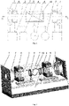
- the bi-directional wave plasma thruster for spacecraft comprises a gas discharge chamber defining thrust axis, antenna, RF generator module electrically coupled with antenna, magnetic systems, wherein the gas discharge chamber is configured open to outer atmosphere from two opposite end-faces to form two thrust vectors opposite in direction and having common axis being the axis of the gas discharge chamber, while the antenna is on the outer surface of the gas discharge chamber and is surrounded by a ring of dielectric material from its outer side, and there is one magnetic system on each opposite end of the gas discharge chamber, while the gas discharge chamber has a gas dynamic connection line with a propellant supply and storage system by means of two radial gas feedthroughs tightly connected to the gas discharge chamber in two places upstream of the magnetic systems.
- Each of the magnetic systems consists of two electromagnets connected to the power sources of magnetic systems.
- the first electromagnet is configured to generate a magnetic field that is transversal to the axis of the corresponding gas discharge chamber
- the second electromagnet is configured to generate axial magnetic field that is parallel to the axis of the corresponding gas discharge chamber, wherein the first electromagnet is farther from the corresponding end-face of the gas discharge chamber than the second electromagnet.
- the thruster additionally comprises rigid structure components consisting of rods composing a frame, which the structure components of bi-directional wave plasma thruster for spacecraft are fixed to.
- the thruster additionally comprises the electromagnetic shielding system consisting of the components covering the outer surface of the rigid structure components and absorbing electromagnetic radiation.
- the thruster additionally comprises a control module configured to form controlling actions on the systems and modules of the bi-directional wave plasma thruster for spacecraft, to collect information on the thruster systems and modules characteristics, and also to transmit the collected information to the spacecraft for following transmission to the ground station.
- a control module configured to form controlling actions on the systems and modules of the bi-directional wave plasma thruster for spacecraft, to collect information on the thruster systems and modules characteristics, and also to transmit the collected information to the spacecraft for following transmission to the ground station.
- the bi-directional wave plasma thruster for spacecraft is proposed to be used onboard satellites, including small satellites, for transferring it from parking orbit to the target orbit, orbit maintenance, attitude control, altitude control, unloading attitude control systems, maneuvers between orbits, and de-orbiting.
- the claimed thruster is bi-directional and consists of the following components with their functions:
- the gas discharge chamber (2) upstream of the electromagnets (5) and (6) of the magnetic system has tight connection to the radial gas feedthroughs of the propellant supply and storage system (3);
- the thruster could also additionally comprise:
- One of the main tasks solved by the bi-directional wave plasma thruster for spacecraft is creation of two thrust vectors making controlling actions on a spacecraft for transferring it from parking orbit to the target orbit, orbit maintenance, attitude control, altitude control, unloading attitude control systems, maneuvers between orbits, and de-orbiting.
- EP using magnetic nozzles are classified as electromagnetic and include magnetoplasmadynamic, helicon, electron cyclotron resonance (ECR), ion cyclotron resonance (ICR), microwave (MW) thrusters, and Direct Fusion Drive. These cutting-edge thrusters are necessary to comply with the requirements of future space missions and are developed to generate specific impulse and specific thrust higher than the existing EP have with the same power level.
- Magnetic nozzles represented in the invention as electromagnets (5), like Laval nozzles, convert thermal energy of propellant particles into directed kinetic energy.
- the advantage of magnetic nozzles is that contact of high-temperature plasma with the magnetic nozzle surface is minimized, while the magnetic nozzles enable to use additional mechanisms of thrust formation due to interaction of electromagnetic fields of plasma and magnetic field of the magnetic nozzle.
- the mechanisms by which thermal energy is extracted from the plasma using electromagnets (5) of magnetic systems include the law of conservation of the adiabatic invariant of the magnetic moment, the electric field forces, the direction of thermal energy, and Joule heating.
- the mechanisms of plasma separation include resistive diffusion of the magnetic field, recombination processes in the plasma, magnetic reconnection of magnetic field lines, loss of adiabaticity of the plasma expansion process, the effects of inertial forces, and the effects of stratification of the lines of self-induced electromagnetic fields.
- the process of pulse transmission from the plasma to the spacecraft is a consequence of the interaction between the lines of the applied magnetic field created by the electromagnet of the magnetic system (50) and the induced flows that are formed due to the magnetic pressure.
- Particle magnetic moment is adiabatically constant during motion, if the magnetic field variation at one period of cyclotron motion is many times less than the magnitude of the magnetic field.
- Electrostatic acceleration could be caused by formation of ambipolar fields or double layers. These mechanisms are the result of high mobility of electrons as compared to ions. This high mobility is characterized by thermal velocity. Mobile electrons in the diverging magnetic nozzles form electron pressure gradient ahead of slow ions. Electrical field which accelerates ions and slows down electrons is formed to maintain quasi-neutrality. This results in energy exchange between electron thermal velocity and ion flow velocity.
- Double layers are characterized by electric potential change in the area of several Debye lengths, while electric potential at ambipolar mechanism could be of the order of characteristic length of the system.
- Kinetic energy could be generated by guiding thermal energy.
- Laval nozzles guide thermal motion into axial direction through convergent-divergent physical wall.
- Magnetic nozzles make it by constraining plasma in the required geometric form by means of strong guiding magnetic field.
- Physics of energy conversion is based on hydrodynamics, and magnetic nozzle geometry is defined by interaction between plasma and magnetic field. It is understood that ratios based on hydrodynamics, similar to those used in Laval nozzles analysis, could be used for analysis of this energy conversion, with neglect of losses occurred at magnetic wall formation.
- Plasma constraining could also require formation of current sheet at the boundary between plasma and vacuum. Diffusion and convection processes could deteriorate the current sheet; therefore, they should be understood so that losses caused by nonideality of plasma constraining.
- the right part of the above expression is the expression for heating according to Joule-Lenz law and describes the energy generated by a continuum as a result of energy loss by the electromagnetic field.
- the same part of the expression but with the reversed sign is represented in the equation of the electromagnetic field energy.
- the above design of the claimed bi-directional wave plasma thruster for spacecraft ensures reduction of the thruster weight and dimensions, elimination of power losses on the antenna-plasma electromagnetic coupling line, elimination of electromagnetic radiation to the propulsion system components and spacecraft structure components resulting in spacecraft rotation in space, ensures increasing thruster specific thrust and specific impulse per consumed power unit.
Landscapes
- Engineering & Computer Science (AREA)
- Chemical & Material Sciences (AREA)
- Combustion & Propulsion (AREA)
- Physics & Mathematics (AREA)
- Plasma & Fusion (AREA)
- Mechanical Engineering (AREA)
- General Engineering & Computer Science (AREA)
- Electromagnetism (AREA)
- Spectroscopy & Molecular Physics (AREA)
- Plasma Technology (AREA)
- Remote Sensing (AREA)
- Aviation & Aerospace Engineering (AREA)
- Health & Medical Sciences (AREA)
- General Health & Medical Sciences (AREA)
- Toxicology (AREA)
- Critical Care (AREA)
- Emergency Medicine (AREA)
- Radar, Positioning & Navigation (AREA)
Applications Claiming Priority (1)
| Application Number | Priority Date | Filing Date | Title |
|---|---|---|---|
| RU2020137435A RU2764823C1 (ru) | 2020-11-16 | 2020-11-16 | Двунаправленный волновой плазменный двигатель для космического аппарата |
Publications (1)
| Publication Number | Publication Date |
|---|---|
| EP4001645A1 true EP4001645A1 (fr) | 2022-05-25 |
Family
ID=76482994
Family Applications (1)
| Application Number | Title | Priority Date | Filing Date |
|---|---|---|---|
| EP21179090.2A Withdrawn EP4001645A1 (fr) | 2020-11-16 | 2021-06-11 | Propulseur bidirectionnel à plasma d'ondes pour engin spatial |
Country Status (4)
| Country | Link |
|---|---|
| US (1) | US20220153455A1 (fr) |
| EP (1) | EP4001645A1 (fr) |
| CN (1) | CN114776546A (fr) |
| RU (1) | RU2764823C1 (fr) |
Families Citing this family (4)
| Publication number | Priority date | Publication date | Assignee | Title |
|---|---|---|---|---|
| CN116981146B (zh) * | 2023-06-06 | 2026-04-14 | 兰州空间技术物理研究所 | 一种螺旋波离子源束流发散控制系统 |
| CN116838557A (zh) * | 2023-06-20 | 2023-10-03 | 北京理工大学 | 一种等离子体推进装置 |
| CN119914485B (zh) * | 2025-01-14 | 2026-03-24 | 北京航空航天大学 | 一种开放式磁等离子体热电转换和动能转化调控装置 |
| CN119933969B (zh) * | 2025-03-06 | 2025-09-26 | 北京航空航天大学 | 一种附加磁场的射频离子推力器 |
Citations (4)
| Publication number | Priority date | Publication date | Assignee | Title |
|---|---|---|---|---|
| US6293090B1 (en) | 1998-07-22 | 2001-09-25 | New England Space Works, Inc. | More efficient RF plasma electric thruster |
| RU2445510C2 (ru) | 2004-09-22 | 2012-03-20 | Элвинг Ллс | Ракетный двигатель малой тяги для космического летательного аппарата |
| CN104405603A (zh) | 2014-10-15 | 2015-03-11 | 大连理工大学 | 螺旋波等离子体电推进装置 |
| WO2021154124A1 (fr) * | 2020-01-29 | 2021-08-05 | Андрей Иванович ШУМЕЙКО | Module avec installation motrice plasmique à canaux multiples pour engin spatial de petite taille |
Family Cites Families (3)
| Publication number | Priority date | Publication date | Assignee | Title |
|---|---|---|---|---|
| DE10300776B3 (de) * | 2003-01-11 | 2004-09-02 | Thales Electron Devices Gmbh | Ionenbeschleuniger-Anordnung |
| CN102767497B (zh) * | 2012-05-22 | 2014-06-18 | 北京卫星环境工程研究所 | 基于空间原子氧的无燃料航天器推进系统及推进方法 |
| RU2703854C1 (ru) * | 2018-11-28 | 2019-10-22 | федеральное государственное бюджетное образовательное учреждение высшего образования "Московский государственный технический университет имени Н.Э. Баумана (национальный исследовательский университет)" (МГТУ им. Н.Э. Баумана) | Двигатель на забортном воздухе с геликонным источником плазмы для поддержания малых космических аппаратов на низкой околоземной орбите |
-
2020
- 2020-11-16 RU RU2020137435A patent/RU2764823C1/ru active
-
2021
- 2021-06-10 US US17/343,993 patent/US20220153455A1/en not_active Abandoned
- 2021-06-11 EP EP21179090.2A patent/EP4001645A1/fr not_active Withdrawn
- 2021-07-05 CN CN202110758784.4A patent/CN114776546A/zh active Pending
Patent Citations (4)
| Publication number | Priority date | Publication date | Assignee | Title |
|---|---|---|---|---|
| US6293090B1 (en) | 1998-07-22 | 2001-09-25 | New England Space Works, Inc. | More efficient RF plasma electric thruster |
| RU2445510C2 (ru) | 2004-09-22 | 2012-03-20 | Элвинг Ллс | Ракетный двигатель малой тяги для космического летательного аппарата |
| CN104405603A (zh) | 2014-10-15 | 2015-03-11 | 大连理工大学 | 螺旋波等离子体电推进装置 |
| WO2021154124A1 (fr) * | 2020-01-29 | 2021-08-05 | Андрей Иванович ШУМЕЙКО | Module avec installation motrice plasmique à canaux multiples pour engin spatial de petite taille |
Non-Patent Citations (5)
| Title |
|---|
| BOMBARDELLI C ET AL: "Ion Beam Shepherd for Contactless Space Debris Removal", ARXIV.ORG, CORNELL UNIVERSITY LIBRARY, 201 OLIN LIBRARY CORNELL UNIVERSITY ITHACA, NY 14853, 7 February 2011 (2011-02-07), XP080497573, DOI: 10.2514/1.51832 * |
| CHABERTBRAITHWAITE: "Physics of radio-frequency plasmas", 2011, CAMBRIDGE UNIVERSITY PRESS |
| REVIEW OF SCIENTIFIC INSTRUMENTS, vol. 83, no. 8, pages 083508 |
| SHUMEIKOTELEKH: "Journal of Physics: Conference Series", vol. 1393, November 2019, IOP PUBLISHING, article "Probe diagnostics of the plasma plume created by a magnetic nozzle of an inductively coupled plasma source", pages: 012027 |
| TAKAHASHI KAZUNORI ET AL: "Demonstrating a new technology for space debris removal using a bi-directional plasma thruster", SCIENTIFIC REPORTS, vol. 8, no. 1, 1 December 2018 (2018-12-01), pages 14417, XP055863844, Retrieved from the Internet <URL:https://www.nature.com/articles/s41598-018-32697-4.pdf> DOI: 10.1038/s41598-018-32697-4 * |
Also Published As
| Publication number | Publication date |
|---|---|
| CN114776546A (zh) | 2022-07-22 |
| RU2764823C1 (ru) | 2022-01-21 |
| US20220153455A1 (en) | 2022-05-19 |
Similar Documents
| Publication | Publication Date | Title |
|---|---|---|
| EP4001645A1 (fr) | Propulseur bidirectionnel à plasma d'ondes pour engin spatial | |
| US6334302B1 (en) | Variable specific impulse magnetoplasma rocket engine | |
| Mazouffre | Electric propulsion for satellites and spacecraft: established technologies and novel approaches | |
| US11365016B2 (en) | Electrodeless plasma thruster | |
| Rafalskyi et al. | Brief review on plasma propulsion with neutralizer-free systems | |
| US11325727B2 (en) | Converging/diverging magnetic nozzle | |
| Koizumi et al. | Miniature microwave discharge ion thruster driven by 1 watt microwave power | |
| Shumeiko et al. | Development of a novel wave plasma propulsion module with six-directional thrust vectoring capability | |
| RU2741401C1 (ru) | Модуль с многоканальной плазменной двигательной установкой для малого космического аппарата | |
| Conversano et al. | Development of and acceptance test preparations for the thruster component of the ascendant sub-kW transcelestial electric propulsion system (ASTRAEUS) | |
| AU2004273099A1 (en) | Method and device for generating alfven waves | |
| US12012234B2 (en) | Electrodeless plasma thruster with closed-ring-shaped gas discharge chamber | |
| Vereen et al. | Recent advances in the clustering of high power helicon thrusters | |
| Cassady et al. | VASIMR technological advances and first stage performance results | |
| Zhil’tsov et al. | Fusion and Space | |
| RU2764487C1 (ru) | Гибридный волновой плазменный двигатель для низкоорбитального космического аппарата | |
| Mistoco et al. | Development and chamber testing of a miniature radio-frequency ion thruster for microspacecraft | |
| Nishiyama et al. | The ion engine system for hayabusa2 | |
| Tahara et al. | Overview of electric propulsion activity in Japan | |
| PATRICK | A description of a propulsive device which employs a magnetic field as the driving force | |
| Schmidt et al. | Recent Electric Propulsion-related activities at DLR’s STG-ET facility | |
| Komurasaki et al. | An Overview of Electric and Advanced Propulsion Activities in Japan | |
| SATELLITE’S | GRADUATE SCHOOL | |
| Stallard et al. | Plasma confinement in the whistler wave plasma thruster | |
| Rakhimova et al. | Ignition Characteristics of an Electrodeless Plasma Thruster with Magnetic Thrust-Vectoring Utilizing Krypton |
Legal Events
| Date | Code | Title | Description |
|---|---|---|---|
| PUAI | Public reference made under article 153(3) epc to a published international application that has entered the european phase |
Free format text: ORIGINAL CODE: 0009012 |
|
| STAA | Information on the status of an ep patent application or granted ep patent |
Free format text: STATUS: THE APPLICATION HAS BEEN PUBLISHED |
|
| AK | Designated contracting states |
Kind code of ref document: A1 Designated state(s): AL AT BE BG CH CY CZ DE DK EE ES FI FR GB GR HR HU IE IS IT LI LT LU LV MC MK MT NL NO PL PT RO RS SE SI SK SM TR |
|
| STAA | Information on the status of an ep patent application or granted ep patent |
Free format text: STATUS: REQUEST FOR EXAMINATION WAS MADE |
|
| 17P | Request for examination filed |
Effective date: 20221122 |
|
| RBV | Designated contracting states (corrected) |
Designated state(s): AL AT BE BG CH CY CZ DE DK EE ES FI FR GB GR HR HU IE IS IT LI LT LU LV MC MK MT NL NO PL PT RO RS SE SI SK SM TR |
|
| STAA | Information on the status of an ep patent application or granted ep patent |
Free format text: STATUS: THE APPLICATION IS DEEMED TO BE WITHDRAWN |
|
| 18D | Application deemed to be withdrawn |
Effective date: 20240103 |