EP4001657A1 - Kaltspritzverstärkte lüfterradabdeckung - Google Patents
Kaltspritzverstärkte lüfterradabdeckung Download PDFInfo
- Publication number
- EP4001657A1 EP4001657A1 EP20209619.4A EP20209619A EP4001657A1 EP 4001657 A1 EP4001657 A1 EP 4001657A1 EP 20209619 A EP20209619 A EP 20209619A EP 4001657 A1 EP4001657 A1 EP 4001657A1
- Authority
- EP
- European Patent Office
- Prior art keywords
- impeller
- layer
- metallic material
- chosen
- group
- Prior art date
- Legal status (The legal status is an assumption and is not a legal conclusion. Google has not performed a legal analysis and makes no representation as to the accuracy of the status listed.)
- Granted
Links
Images


Classifications
-
- F—MECHANICAL ENGINEERING; LIGHTING; HEATING; WEAPONS; BLASTING
- F04—POSITIVE - DISPLACEMENT MACHINES FOR LIQUIDS; PUMPS FOR LIQUIDS OR ELASTIC FLUIDS
- F04D—NON-POSITIVE-DISPLACEMENT PUMPS
- F04D29/00—Details, component parts, or accessories
- F04D29/26—Rotors specially for elastic fluids
- F04D29/28—Rotors specially for elastic fluids for centrifugal or helico-centrifugal pumps for radial-flow or helico-centrifugal pumps
- F04D29/284—Rotors specially for elastic fluids for centrifugal or helico-centrifugal pumps for radial-flow or helico-centrifugal pumps for compressors
-
- C—CHEMISTRY; METALLURGY
- C23—COATING METALLIC MATERIAL; COATING MATERIAL WITH METALLIC MATERIAL; CHEMICAL SURFACE TREATMENT; DIFFUSION TREATMENT OF METALLIC MATERIAL; COATING BY VACUUM EVAPORATION, BY SPUTTERING, BY ION IMPLANTATION OR BY CHEMICAL VAPOUR DEPOSITION, IN GENERAL; INHIBITING CORROSION OF METALLIC MATERIAL OR INCRUSTATION IN GENERAL
- C23C—COATING METALLIC MATERIAL; COATING MATERIAL WITH METALLIC MATERIAL; SURFACE TREATMENT OF METALLIC MATERIAL BY DIFFUSION INTO THE SURFACE, BY CHEMICAL CONVERSION OR SUBSTITUTION; COATING BY VACUUM EVAPORATION, BY SPUTTERING, BY ION IMPLANTATION OR BY CHEMICAL VAPOUR DEPOSITION, IN GENERAL
- C23C24/00—Coating starting from inorganic powder
- C23C24/02—Coating starting from inorganic powder by application of pressure only
- C23C24/04—Impact or kinetic deposition of particles
-
- F—MECHANICAL ENGINEERING; LIGHTING; HEATING; WEAPONS; BLASTING
- F01—MACHINES OR ENGINES IN GENERAL; ENGINE PLANTS IN GENERAL; STEAM ENGINES
- F01D—NON-POSITIVE DISPLACEMENT MACHINES OR ENGINES, e.g. STEAM TURBINES
- F01D5/00—Blades; Blade-carrying members; Heating, heat-insulating, cooling or antivibration means on the blades or the members
- F01D5/02—Blade-carrying members, e.g. rotors
-
- F—MECHANICAL ENGINEERING; LIGHTING; HEATING; WEAPONS; BLASTING
- F04—POSITIVE - DISPLACEMENT MACHINES FOR LIQUIDS; PUMPS FOR LIQUIDS OR ELASTIC FLUIDS
- F04D—NON-POSITIVE-DISPLACEMENT PUMPS
- F04D29/00—Details, component parts, or accessories
- F04D29/02—Selection of particular materials
- F04D29/023—Selection of particular materials especially adapted for elastic fluid pumps
-
- F—MECHANICAL ENGINEERING; LIGHTING; HEATING; WEAPONS; BLASTING
- F05—INDEXING SCHEMES RELATING TO ENGINES OR PUMPS IN VARIOUS SUBCLASSES OF CLASSES F01-F04
- F05D—INDEXING SCHEME FOR ASPECTS RELATING TO NON-POSITIVE-DISPLACEMENT MACHINES OR ENGINES, GAS-TURBINES OR JET-PROPULSION PLANTS
- F05D2230/00—Manufacture
- F05D2230/30—Manufacture with deposition of material
- F05D2230/31—Layer deposition
-
- F—MECHANICAL ENGINEERING; LIGHTING; HEATING; WEAPONS; BLASTING
- F05—INDEXING SCHEMES RELATING TO ENGINES OR PUMPS IN VARIOUS SUBCLASSES OF CLASSES F01-F04
- F05D—INDEXING SCHEME FOR ASPECTS RELATING TO NON-POSITIVE-DISPLACEMENT MACHINES OR ENGINES, GAS-TURBINES OR JET-PROPULSION PLANTS
- F05D2250/00—Geometry
- F05D2250/20—Three-dimensional
- F05D2250/29—Three-dimensional machined; miscellaneous
- F05D2250/294—Three-dimensional machined; miscellaneous grooved
-
- F—MECHANICAL ENGINEERING; LIGHTING; HEATING; WEAPONS; BLASTING
- F05—INDEXING SCHEMES RELATING TO ENGINES OR PUMPS IN VARIOUS SUBCLASSES OF CLASSES F01-F04
- F05D—INDEXING SCHEME FOR ASPECTS RELATING TO NON-POSITIVE-DISPLACEMENT MACHINES OR ENGINES, GAS-TURBINES OR JET-PROPULSION PLANTS
- F05D2300/00—Materials; Properties thereof
- F05D2300/10—Metals, alloys or intermetallic compounds
- F05D2300/17—Alloys
- F05D2300/173—Aluminium alloys, e.g. AlCuMgPb
-
- F—MECHANICAL ENGINEERING; LIGHTING; HEATING; WEAPONS; BLASTING
- F05—INDEXING SCHEMES RELATING TO ENGINES OR PUMPS IN VARIOUS SUBCLASSES OF CLASSES F01-F04
- F05D—INDEXING SCHEME FOR ASPECTS RELATING TO NON-POSITIVE-DISPLACEMENT MACHINES OR ENGINES, GAS-TURBINES OR JET-PROPULSION PLANTS
- F05D2300/00—Materials; Properties thereof
- F05D2300/10—Metals, alloys or intermetallic compounds
- F05D2300/17—Alloys
- F05D2300/174—Titanium alloys, e.g. TiAl
Definitions
- the subject matter of the present disclosure relates to a shrouded impeller and to a method for manufacturing shrouded impellers, in particular for centrifugal compressors, characterized by a reduced mechanical stress caused by the applied centrifugal forces during operation, and adapted to perform at higher peripheral speed with respect to the state-of-the-art technology, without incurring in structural problems.
- Radial flow turbo machinery devices are adapted to convert shaft power to kinetic energy (and vice versa) by accelerating (or decelerating) a fluid in a revolving device called impeller.
- impellers When used as power-absorbing machines, impellers are commonly used to raise the pressure of a fluid or induce a fluid flow in a piping system.
- the impeller is the device, within the centrifugal compressors and the turbo machinery in general, that, rotating, exchanges energy with the fluid.
- the impeller comprises a plurality of blades fitted onto a hub plate.
- the shape and the geometry of impeller blades can be of many different types depending on the use, the rating, the performance of the turbo machinery.
- a compressor for instance, is a machine adapted to accelerate the particles of a compressible fluid, e.g., a gas, through the use of mechanical energy to increase the pressure of that compressible fluid.
- Compressors are used in a number of different applications, including gas turbines engines.
- the various types of compressors are the centrifugal compressors, in which the mechanical energy operates on the gas input to the compressor by way of centrifugal acceleration which accelerates the gas particles, e.g., by rotating a centrifugal impeller through which the gas is passing.
- centrifugal compressors are part of a class of machinery generally referred to as "turbo machines" or “turbo rotating machines”.
- Compressors and centrifugal compressors in particular, can be fitted with a single impeller, i.e., a single stage configuration, or with a plurality of impellers in series, in which case they are frequently referred to as multistage compressors.
- Each of the stages of a centrifugal compressor typically includes an inlet conduit for gas to be accelerated, an impeller which is capable of providing energy to the gas and a diffuser which converts part of the kinetic energy of the gas leaving the impeller into pressure.
- Impellers can be shrouded or unshrouded.
- Centrifugal Compressors may often employ unshrouded, or open, impellers to accelerate or apply energy to the process fluid, as the open impellers may often be relatively easier to manufacture and, typically, allow for higher peripheral speed with respect to shrouded, or closed, impellers.
- the centrifugal compressors employing open impellers may exhibit decreased performance and/or efficiencies, for example due to the fact that a portion of the process fluid may flow or leak out of the open impellers through clearances defined between the blades and the statoric part of the compressor, thereby reducing the overall efficiency thereof.
- centrifugal compressors may often employ shrouded impellers with at least one seal between the statoric part and the shroud in order to reduce or eliminate the clearances between said statoric part and the impeller and allow larger relative displacements.
- shrouded impellers are not free from drawbacks. The outer periphery of both shrouded and unshrouded impellers can be distorted as a result of the centrifugal forces developing during operation due to the impeller high rotational speed.
- shrouded impellers are subject to a much higher stress and typically allow for lower peripheral speed with respect to unshrouded impellers.
- shrouded impellers allow a better efficiency while they are more prone to suffer mechanical stress that limits the maximum allowable impeller peripheral speed and, consequently, the maximum head that can be provided to the processed fluid.
- Impellers provided with shrouds made of carbon fiber are known in the art, however, carbon fiber material is fragile and subject to the attack of gasses. Moreover, coupling a shroud in carbon fiber to a steel impeller, comprising a hub and a number of blades, is extremely difficult due to the very different relative deformations of shroud and impeller at high peripheral speeds and due to the fact that carbon fiber doesn't do plastic deformation.
- impellers with shrouds made of carbon fiber are therefore rarely employed in extreme industrial applications such as Oil & Gas industrial applications.
- a problem which is relevant in the state of the art is therefore how to provide shrouded impellers adapted to withstand the centrifugal forces at high peripheral speed, allowing levels of power density close to the power density levels of unshrouded impellers.
- Embodiments of the present disclosure therefore relate to a shrouded impeller and to a method for manufacturing shrouded impellers, in particular for turbo machines.
- the method described herein employs known techniques of additive manufacturing and, in particular, cold spray additive manufacturing to add one or more layers of appropriate materials on the impeller hub and/or on the impeller shroud.
- the cold spray process is a solid-state coating deposition technology that has recently established as an additive manufacturing process. In comparison with high-temperature additive manufacturing processes, cold spray additive manufacturing produces oxide-free deposits and has proved better in retaining the original properties of the raw material to process without damaging it during manufacturing.
- Embodiments of the present disclosure further relates to impellers and impeller shrouds provided with added material deposited through cold spray additive manufacturing and adapted to reduce the stresses of the impeller subject to rotation with high peripheral speed.
- the material deposited by cold spray additive manufacturing may comprise multiple layers, each one with a specific shape, material and/or characteristic, according to the needs.
- Preferred embodiments comprising one, two, three and four deposited layers are described and examples of metal base alloys to manufacture said layers are given.
- Embodiments comprising more than four deposited layers are within the scope of the present disclosure, as well.
- each example embodies geometries adapted to optimize cohesion between layers and the performance of the impeller with respect to a wide range of impeller geometries, excitations, natural vibration frequencies and working temperatures.
- the geometries of the described deposited layers are adapted to modify the local natural frequencies and can be tuned in order to avoid dangerous crossings between natural and exciting frequencies that can be harmful to the integrity of the impeller.
- the stiffness and the density of the employed material the key to determine the vibration frequency of an object, then employing, for the shroud according to the present disclosure, different materials of various thickness allows modifying the local stiffness and density of the shroud based on the thickness of the different materials the shroud is made of.
- the illustrated shapes and geometries can be chosen to optimize the cohesion between the base material and the added material.
- the added material is preferably deposited in several areas delimited by a plurality of lines of no added material. The number of said lines can be made proportional to the number of the blades of the impeller.
- Centrifugal compressors are a class of turbo machines - or turbo rotating machines - adapted to accelerate the particles of an input compressible fluid, e.g., a gas, through the use of mechanical energy to increase the pressure thereof. Centrifugal compressors exploit centrifugal acceleration to accelerate the input gas particles, e.g., by rotating a centrifugal impeller through which the gas is forced to flow.
- an input compressible fluid e.g., a gas
- Centrifugal compressors may employ closed or open impellers, that is impellers manufactured with or without a shroud.
- Shrouded impellers guarantee higher efficiency but have a lower maximum allowable peripheral speed and, consequently, a lower maximum head to provide to the processed fluid.
- Embodiments described herein refer to a shrouded impeller and to a method to build multi-material shrouded impellers suitable to rotate with peripheral speed higher than the one reachable with single material shrouded impellers.
- the method comprises depositing, on the shroud of a pre-machined impeller base material, additional material by cold spray additive manufacturing.
- the material deposited by cold spray additive manufacturing may comprise single or multiple layers, each one with a specific shape and/or material and/or characteristic.
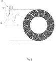
- One embodiment of the impeller 10 comprises a hub 11, adapted to host a driving shaft that provides the power to be transmitted to the process fluid, and a shroud 12.
- a plurality of blades 13 are interposed between the hub 11 and the shroud 12. Vanes develop outwardly from the hub 11 and are shaped in such a way to displace the working fluid from a low-pressure side inlet - the impeller eye, placed on the shroud in a frontal area of the impeller 10 - to a high-pressure side outlet located at the periphery of the impeller 10.
- the working fluid enters in the vanes between the blades 13, from the impeller eye, along a direction substantially parallel to an axis of rotation of the impeller 10 and exits, energized by the action of the impeller 10, from the outlet defined by a peripheral circumferential edge of the impeller 10.
- the shroud 12 is subject to centrifugal acceleration and forces that cause larger displacements with respect to the hub 11. Being the blades 13 attached to both the shroud 12 and the hub 11 they are subject to much higher stress with respect to unshrouded impellers, and can incur in major damages, if the impeller peripheral speed is not properly limited.
- the centrifugal forces applied by the shroud 12 to the blades are proportional to the mass of the shroud that, for a given geometry, is proportional to its density.
- closed impellers designed to run at very high peripheral speed are made by a single material, for instance a special steel with high yield stress or a low-density material (e.g. titanium or aluminum alloy).
- Closed impellers made by low-density materials compensate the lower resistance of the blades with lower forces generated by the reduced density (about 4500 kg/m3 for titanium and 2700 kg/m3 for aluminum) of the shroud.
- the impeller can be manufactured with one or more metallic materials that can be deposited by cold spray additive manufacturing over a metallic base.
- Cold spraying is a coating deposition method wherein solid powders (generally in the range 1 to 50 micrometers in diameter) are accelerated in a supersonic gas jet to a speed up to 500 - 1000 m/s.
- Metals, polymers, ceramics, composite materials and nanocrystalline powders can be deposited using cold spraying.
- particles undergo plastic deformation and adhere to the treated surface.
- the kinetic energy of the powder particles supplied by the expansion of the gas in the supersonic gas jet, is converted to plastic deformation energy during bonding.
- thermal spraying techniques e.g., plasma spraying, arc spraying, flame spraying, or high velocity oxygen fuel, the powders are not melted during the cold spraying process.
- the shroud 12 of the impeller 10 may comprise a single deposited layer or multiple layers.
- the materials that can be used are, preferably, the following: Al alloys (as AL2024, Al6061, AL7050 etc) or Ti alloys (as Ti6Al4V, Ti6Al4V ELI, Ti Grade 17 etc.) due to low density, high mechanical properties and wide commercial availability.
- a multilayer structure can be envisaged in order to obtain a graded structure wherein the properties of the employed materials change gradually from one layer to the next.
- Multilayer structures thus comprise a plurality of layers deposited on the surface of the impeller shroud 12.
- the heaviest metals or alloys are deposited first in a thin layer, in order to have best adhesion to the impeller shroud 12 surface and minimize mechanical stress when in operation.
- the sequence of the employed layers is chosen in order to make sure that at least one property of the metals or alloys of said layers varies gradually from the first to the last layer deposited.
- Said at least one property can be, for instance, molecular weight or molar mass, density, CTE, Young modulus etc.
- a second layer is deposited on top of the first layer, the second layer being made of a lighter material with respect to the material of the first layer.
- the first, heavier layer can be made, for instance, of Fe or Ni alloys.
- the second, lighter, layer can be made of metals or alloys of Al, Mg, Ti and Fe when the first layer is made of Ni.
- Embodiments of the impeller provided with a two-layer structure and according to the disclosure may employ the following combinations of metals or alloys (first metal / alloy being referred to the first or inner layer, second metal / alloy being referred to the second or outer layer): Fe - Al; Ni - Al; Fe - Mg; Ni - Mg; Fe - Ti; Ni - Ti; Ni - Fe.
- one embodiment comprises an intermediate third layer interposed between the above described two layers and another embodiment comprises one additional third layer placed on top of the other two layers to protect the structure from corrosion, erosion or wear due to the environment.
- a first, heavier layer is deposited by cold spraying on the impeller shroud, then an intermediate second layer is cold sprayed on the first layer to minimize mechanical stress between different layers.
- a third, lighter layer is deposited on top of the second layer.
- Embodiments of three-layer shroud 12 of the impeller according to the disclosure may employ an intermediate layer made of the following metals or alloys: Al, Ti, Mg, Fe, Ni, Co, Mo, Cr.
- Preferred examples of three layers shrouds may employ the following sequences of metals or alloys, wherein the metal or alloy mentioned first is the first to be cold sprayed on the shroud: Ti-AI-Mg, Ni-Fe-Ti, Ni-Fe-AI, Ni-Ti-AI, Fe-Ti-AI, Co-Ni-AI. All the above examples provide a sequence of metals / alloys characterised by at least one property varying gradually from the first to the last layer deposited.
- Ti-AI-Mg for instance, Ti has physical properties which are in between the steel substrate and the following layer of Al.
- an additional, external layer helpful to provide extra resistance against corrosion, erosion and wear.
- An additional, external layer can be deposited on top of the single, double or triple layer cold sprayed on the shroud surface, to strengthen the structure against aggressive environment agents. Examples of this additional, external layer may be made of the following metals or alloys: Ti, Ni, Co, Mo , and Cr.
- an impeller body can be manufactured with different technologies (e.g. forged, casted, hipped or 3D printed) and in a wide choice of materials, e.g. steel, (for instance AISI410, ASTM A182 F22, 17-4PH etc.) or Ni alloy (for instance IN625M PM, IN718 etc.).
- the impeller body is pre-machined by processes of turning and milling, then single or multiple layers of metal or metal alloys are deposited by cold spraying on the surface of the frontal part of the impeller where the shroud will be; finally the impeller is machined to manufacture the complete structure of the impeller comprising blades and vanes.
- the final machining of the impeller will be adapted to suitably shape the shroud, choosing the width of the base material with respect to the width of the cold sprayed external materials optimizing the overall characteristics of the impeller to maximize the allowable peripheral speed and maximum power transmissible to the gas.
- the final machining is adapted to completely remove the base layer of original steel of the shroud in order to leave only the cold spray deposited layers.
- impeller base material is pre-machined and then it is further machined to manufacture the complete structure of the impeller comprising blades and vanes. Finally the shroud of the impeller is cold sprayed to add one or more layers of metal or metal alloys.
- the impeller base material is pre-machined by processes of turning and milling to manufacture the structure of the impeller comprising blades and vanes. Then the shroud of the impeller is cold sprayed to add one or more layers of metal or metal alloys.
- one or more of the additional cold sprayed layers is not even but it is made of a plurality of sectors, separated from the adjacent ones by a plurality of grooves 14 where no additional material has been deposited or where the deposited material has a thinner width.
- the radial grooves originate from the inner edge of the shroud, run to the outer edge of the shroud and are approximately centered in the center of the eye of the impeller.
- the number of grooves can be chosen based on the impeller requirements (number of blades, peripheral speed, exciting frequencies etc.).
- the number and the shape of the grooves can be useful to tune the local natural resonance frequencies thus allowing the designer to clear said natural resonance frequencies from the exciting frequencies that are potentially very harmful to the impeller. Furthermore, the number and the shape of the grooves can be suitably chosen for reducing the stress on the deposited layers.
- the grooves are still substantially radial but curved.
- Fig. 3 shows another embodiment wherein a plurality of couples of grooves, one curved and one straight, originates from the inner edge of the shroud in an approximately radial fashion and run to the outer edge of the shroud.
- the straight groove of each couple intersect with the curved groove of the following couple.
- Fig. 4 shows one more embodiment wherein a plurality of couples of straight grooves originates from the inner edge of the shroud in an approximately radial fashion and run to the outer edge of the shroud.
- Each groove of each couple of grooves intersects with one groove of two following or two previous couples of grooves.
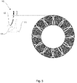
- Fig. 5 shows another embodiment wherein a plurality of couples of curved grooves originates from the inner edge of the shroud in an approximately radial fashion and run to the outer edge of the shroud.
- the curved grooves of each couple intersect with each other and have their concavities facing each other.
- Fig. 6 shows another embodiment wherein a plurality of straight grooves are arranged like chords of the approximately circular outer edge of the shroud of the impeller. Each groove intersects with at least two other grooves.
- Fig. 7 shows another embodiment wherein a plurality of curved and straight grooves originates from the inner edge of the shroud in an approximately radial fashion and run to the outer edge of the shroud. Each straight groove intersects with at least one adjacent curved groove.
- Fig. 8 shows another embodiment wherein two circular grooves divides the surface of the shroud into three circular crowns.
- Fig. 9 shows another embodiment wherein two quasi-elliptical grooves divides the surface of the shroud into three sections.
- Fig. 10 shows another embodiment wherein a plurality of quasi-elliptical grooves divides the surface of the shroud into a plurality of sections.
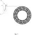
- Fig. 11 shows another embodiment wherein a plurality of couples of curved grooves originates from the inner edge of the shroud in an approximately radial fashion, run to the outer edge of the shroud and intersect with two circular grooves to divide the surface of the shroud into a plurality of sections.
- All the previously described embodiments are aimed at optimizing the dynamic behavior of the impeller by modifying and tuning the local natural frequencies in order to avoid dangerous crossings between natural and exciting frequencies that can be harmful to the integrity of the impeller when in operation.
Landscapes
- Engineering & Computer Science (AREA)
- Mechanical Engineering (AREA)
- General Engineering & Computer Science (AREA)
- Chemical & Material Sciences (AREA)
- Chemical Kinetics & Catalysis (AREA)
- Materials Engineering (AREA)
- Metallurgy (AREA)
- Organic Chemistry (AREA)
- Structures Of Non-Positive Displacement Pumps (AREA)
Priority Applications (3)
| Application Number | Priority Date | Filing Date | Title |
|---|---|---|---|
| ES20209619T ES2985703T3 (es) | 2020-11-24 | 2020-11-24 | Cubierta de impulsor reforzada por pulverización en frío |
| EP20209619.4A EP4001657B1 (de) | 2020-11-24 | 2020-11-24 | Kaltspritzverstärkte lüfterradabdeckung |
| US17/103,535 US20220163047A1 (en) | 2020-11-24 | 2020-11-24 | Cold spray reinforced impeller shroud |
Applications Claiming Priority (1)
| Application Number | Priority Date | Filing Date | Title |
|---|---|---|---|
| EP20209619.4A EP4001657B1 (de) | 2020-11-24 | 2020-11-24 | Kaltspritzverstärkte lüfterradabdeckung |
Publications (2)
| Publication Number | Publication Date |
|---|---|
| EP4001657A1 true EP4001657A1 (de) | 2022-05-25 |
| EP4001657B1 EP4001657B1 (de) | 2024-06-26 |
Family
ID=73597833
Family Applications (1)
| Application Number | Title | Priority Date | Filing Date |
|---|---|---|---|
| EP20209619.4A Active EP4001657B1 (de) | 2020-11-24 | 2020-11-24 | Kaltspritzverstärkte lüfterradabdeckung |
Country Status (3)
| Country | Link |
|---|---|
| US (1) | US20220163047A1 (de) |
| EP (1) | EP4001657B1 (de) |
| ES (1) | ES2985703T3 (de) |
Citations (5)
| Publication number | Priority date | Publication date | Assignee | Title |
|---|---|---|---|---|
| EP2022987A1 (de) * | 2007-07-27 | 2009-02-11 | Napier Turbochargers Limited | Laufrad und Herstellungsverfahren dafür |
| EP2612954A2 (de) * | 2012-01-05 | 2013-07-10 | General Electric Company | Auftragen einer Haftbeschichtung mit Kaltspray-Verfahren und Artikel daraus |
| WO2013124314A1 (en) * | 2012-02-23 | 2013-08-29 | Nuovo Pignone Srl | Turbo-machine impeller manufacturing |
| US20150044048A1 (en) * | 2013-08-07 | 2015-02-12 | Samsung Techwin Co., Ltd. | Impeller assembly of fluid rotary machine and manufacturing method thereof |
| EP3081669A1 (de) * | 2015-04-17 | 2016-10-19 | Hermle Maschinenbau GmbH | Verfahren zur herstellung von gedeckelten laufrädern |
Family Cites Families (11)
| Publication number | Priority date | Publication date | Assignee | Title |
|---|---|---|---|---|
| US3642379A (en) * | 1969-06-27 | 1972-02-15 | Judson S Swearingen | Rotary gas-handling machine and rotor therefor free of vibration waves in operation |
| US3893787A (en) * | 1974-03-14 | 1975-07-08 | United Aircraft Corp | Centrifugal compressor boundary layer control |
| JP3516530B2 (ja) * | 1995-07-28 | 2004-04-05 | 日機装株式会社 | 低比速度インペラ |
| US6250880B1 (en) * | 1997-09-05 | 2001-06-26 | Ventrassist Pty. Ltd | Rotary pump with exclusively hydrodynamically suspended impeller |
| JP4458109B2 (ja) * | 2007-03-27 | 2010-04-28 | 株式会社日立プラントテクノロジー | 溶接溝封止構造 |
| JP5061836B2 (ja) * | 2007-10-10 | 2012-10-31 | 株式会社日立プラントテクノロジー | 羽根車の溶接方法及び羽根車 |
| US9696122B2 (en) * | 2011-06-30 | 2017-07-04 | Imi Systems Ltd. | Antiballistic article and method of producing same |
| KR101465052B1 (ko) * | 2013-04-12 | 2014-11-25 | 두산중공업 주식회사 | 원심압축기의 쉬라우드 임펠러 및 그 제조방법 |
| IT201900007758A1 (it) * | 2019-05-31 | 2020-12-01 | Nuovo Pignone Tecnologie Srl | Anello di girante rinforzato tramite deposizione a freddo |
| KR102320558B1 (ko) * | 2020-02-18 | 2021-11-02 | 엘지전자 주식회사 | 임펠러 및 그 제조 방법 |
| US12397493B2 (en) * | 2020-03-23 | 2025-08-26 | The Boeing Company | Apparatuses, methods, and products for cold spray additive manufacturing of multi curved and reinforced components |
-
2020
- 2020-11-24 EP EP20209619.4A patent/EP4001657B1/de active Active
- 2020-11-24 US US17/103,535 patent/US20220163047A1/en active Pending
- 2020-11-24 ES ES20209619T patent/ES2985703T3/es active Active
Patent Citations (5)
| Publication number | Priority date | Publication date | Assignee | Title |
|---|---|---|---|---|
| EP2022987A1 (de) * | 2007-07-27 | 2009-02-11 | Napier Turbochargers Limited | Laufrad und Herstellungsverfahren dafür |
| EP2612954A2 (de) * | 2012-01-05 | 2013-07-10 | General Electric Company | Auftragen einer Haftbeschichtung mit Kaltspray-Verfahren und Artikel daraus |
| WO2013124314A1 (en) * | 2012-02-23 | 2013-08-29 | Nuovo Pignone Srl | Turbo-machine impeller manufacturing |
| US20150044048A1 (en) * | 2013-08-07 | 2015-02-12 | Samsung Techwin Co., Ltd. | Impeller assembly of fluid rotary machine and manufacturing method thereof |
| EP3081669A1 (de) * | 2015-04-17 | 2016-10-19 | Hermle Maschinenbau GmbH | Verfahren zur herstellung von gedeckelten laufrädern |
Also Published As
| Publication number | Publication date |
|---|---|
| ES2985703T3 (es) | 2024-11-07 |
| US20220163047A1 (en) | 2022-05-26 |
| EP4001657B1 (de) | 2024-06-26 |
Similar Documents
| Publication | Publication Date | Title |
|---|---|---|
| EP2613015B1 (de) | Äußere hybride Laufschaufelluftdichtung für einen Gasturbinenmotor | |
| US9138838B2 (en) | Method of repairing a turbine rotor using cold spraying | |
| JP5981691B2 (ja) | 傾斜機能材料を用いたジャケットインペラ及びその作製方法 | |
| US6059533A (en) | Damped blade having a single coating of vibration-damping material | |
| US11859499B2 (en) | Turbine clearance control coatings and method | |
| EP1970147B1 (de) | Herstellungsverfahren für ein Rotorbauteil aus einer Superlegierung | |
| WO2000017490A2 (en) | Methods for repairing and reclassifying airfoil parts | |
| WO2006075994A2 (en) | Cold gas-dynamic spraying of wear resistant alloys on turbine blades | |
| EP2601428B1 (de) | Bimetallische rotordichtungen mit geringer durchbiegung | |
| IT201900007758A1 (it) | Anello di girante rinforzato tramite deposizione a freddo | |
| EP4001657B1 (de) | Kaltspritzverstärkte lüfterradabdeckung | |
| CN106574506A (zh) | 蒸汽涡轮动叶片、蒸汽涡轮动叶片的制造方法及蒸汽涡轮 | |
| US8956700B2 (en) | Method for adhering a coating to a substrate structure | |
| EP2230037A1 (de) | Verfahren zur Herstellung eines Laufrads mit doppelter Mikrostruktur | |
| KR102063760B1 (ko) | 기능성 코팅부를 구비한 터보 기계 부품 | |
| EP4563791A1 (de) | Dichtring | |
| US20250224034A1 (en) | Light weight hybrid piston seal ring | |
| EP3472472B1 (de) | Schichtsystem, laufrad, verfahren zur herstellung | |
| US20250320822A1 (en) | Leading edge plating on low pressure compressor vane for weight and strength optimization | |
| EP4577376A1 (de) | Verfahren zur herstellung eines laufrades und laufrad | |
| EP3199659A1 (de) | Verfahren zur herstellung eines zylindrischen hochtemperaturbauteils für einen gasturbinenmotor | |
| CN115011845A (zh) | 抗微动磨损涂层组合物以及涂层部件 |
Legal Events
| Date | Code | Title | Description |
|---|---|---|---|
| PUAI | Public reference made under article 153(3) epc to a published international application that has entered the european phase |
Free format text: ORIGINAL CODE: 0009012 |
|
| STAA | Information on the status of an ep patent application or granted ep patent |
Free format text: STATUS: THE APPLICATION HAS BEEN PUBLISHED |
|
| AK | Designated contracting states |
Kind code of ref document: A1 Designated state(s): AL AT BE BG CH CY CZ DE DK EE ES FI FR GB GR HR HU IE IS IT LI LT LU LV MC MK MT NL NO PL PT RO RS SE SI SK SM TR |
|
| RAP3 | Party data changed (applicant data changed or rights of an application transferred) |
Owner name: NUOVO PIGNONE TECNOLOGIE S.R.L. |
|
| STAA | Information on the status of an ep patent application or granted ep patent |
Free format text: STATUS: REQUEST FOR EXAMINATION WAS MADE |
|
| 17P | Request for examination filed |
Effective date: 20221116 |
|
| RBV | Designated contracting states (corrected) |
Designated state(s): AL AT BE BG CH CY CZ DE DK EE ES FI FR GB GR HR HU IE IS IT LI LT LU LV MC MK MT NL NO PL PT RO RS SE SI SK SM TR |
|
| P01 | Opt-out of the competence of the unified patent court (upc) registered |
Effective date: 20230526 |
|
| GRAP | Despatch of communication of intention to grant a patent |
Free format text: ORIGINAL CODE: EPIDOSNIGR1 |
|
| STAA | Information on the status of an ep patent application or granted ep patent |
Free format text: STATUS: GRANT OF PATENT IS INTENDED |
|
| INTG | Intention to grant announced |
Effective date: 20240416 |
|
| GRAS | Grant fee paid |
Free format text: ORIGINAL CODE: EPIDOSNIGR3 |
|
| GRAA | (expected) grant |
Free format text: ORIGINAL CODE: 0009210 |
|
| STAA | Information on the status of an ep patent application or granted ep patent |
Free format text: STATUS: THE PATENT HAS BEEN GRANTED |
|
| RAP3 | Party data changed (applicant data changed or rights of an application transferred) |
Owner name: NUOVO PIGNONE TECNOLOGIE - S.R.L. |
|
| AK | Designated contracting states |
Kind code of ref document: B1 Designated state(s): AL AT BE BG CH CY CZ DE DK EE ES FI FR GB GR HR HU IE IS IT LI LT LU LV MC MK MT NL NO PL PT RO RS SE SI SK SM TR |
|
| REG | Reference to a national code |
Ref country code: GB Ref legal event code: FG4D |
|
| REG | Reference to a national code |
Ref country code: CH Ref legal event code: EP |
|
| REG | Reference to a national code |
Ref country code: DE Ref legal event code: R096 Ref document number: 602020032912 Country of ref document: DE |
|
| PG25 | Lapsed in a contracting state [announced via postgrant information from national office to epo] |
Ref country code: BG Free format text: LAPSE BECAUSE OF FAILURE TO SUBMIT A TRANSLATION OF THE DESCRIPTION OR TO PAY THE FEE WITHIN THE PRESCRIBED TIME-LIMIT Effective date: 20240626 |
|
| PG25 | Lapsed in a contracting state [announced via postgrant information from national office to epo] |
Ref country code: FI Free format text: LAPSE BECAUSE OF FAILURE TO SUBMIT A TRANSLATION OF THE DESCRIPTION OR TO PAY THE FEE WITHIN THE PRESCRIBED TIME-LIMIT Effective date: 20240626 Ref country code: HR Free format text: LAPSE BECAUSE OF FAILURE TO SUBMIT A TRANSLATION OF THE DESCRIPTION OR TO PAY THE FEE WITHIN THE PRESCRIBED TIME-LIMIT Effective date: 20240626 |
|
| REG | Reference to a national code |
Ref country code: LT Ref legal event code: MG9D |
|
| PG25 | Lapsed in a contracting state [announced via postgrant information from national office to epo] |
Ref country code: GR Free format text: LAPSE BECAUSE OF FAILURE TO SUBMIT A TRANSLATION OF THE DESCRIPTION OR TO PAY THE FEE WITHIN THE PRESCRIBED TIME-LIMIT Effective date: 20240927 |
|
| PG25 | Lapsed in a contracting state [announced via postgrant information from national office to epo] |
Ref country code: LV Free format text: LAPSE BECAUSE OF FAILURE TO SUBMIT A TRANSLATION OF THE DESCRIPTION OR TO PAY THE FEE WITHIN THE PRESCRIBED TIME-LIMIT Effective date: 20240626 |
|
| REG | Reference to a national code |
Ref country code: NL Ref legal event code: MP Effective date: 20240626 |
|
| PG25 | Lapsed in a contracting state [announced via postgrant information from national office to epo] |
Ref country code: LV Free format text: LAPSE BECAUSE OF FAILURE TO SUBMIT A TRANSLATION OF THE DESCRIPTION OR TO PAY THE FEE WITHIN THE PRESCRIBED TIME-LIMIT Effective date: 20240626 Ref country code: HR Free format text: LAPSE BECAUSE OF FAILURE TO SUBMIT A TRANSLATION OF THE DESCRIPTION OR TO PAY THE FEE WITHIN THE PRESCRIBED TIME-LIMIT Effective date: 20240626 Ref country code: GR Free format text: LAPSE BECAUSE OF FAILURE TO SUBMIT A TRANSLATION OF THE DESCRIPTION OR TO PAY THE FEE WITHIN THE PRESCRIBED TIME-LIMIT Effective date: 20240927 Ref country code: FI Free format text: LAPSE BECAUSE OF FAILURE TO SUBMIT A TRANSLATION OF THE DESCRIPTION OR TO PAY THE FEE WITHIN THE PRESCRIBED TIME-LIMIT Effective date: 20240626 Ref country code: BG Free format text: LAPSE BECAUSE OF FAILURE TO SUBMIT A TRANSLATION OF THE DESCRIPTION OR TO PAY THE FEE WITHIN THE PRESCRIBED TIME-LIMIT Effective date: 20240626 Ref country code: RS Free format text: LAPSE BECAUSE OF FAILURE TO SUBMIT A TRANSLATION OF THE DESCRIPTION OR TO PAY THE FEE WITHIN THE PRESCRIBED TIME-LIMIT Effective date: 20240926 |
|
| REG | Reference to a national code |
Ref country code: ES Ref legal event code: FG2A Ref document number: 2985703 Country of ref document: ES Kind code of ref document: T3 Effective date: 20241107 |
|
| PG25 | Lapsed in a contracting state [announced via postgrant information from national office to epo] |
Ref country code: NL Free format text: LAPSE BECAUSE OF FAILURE TO SUBMIT A TRANSLATION OF THE DESCRIPTION OR TO PAY THE FEE WITHIN THE PRESCRIBED TIME-LIMIT Effective date: 20240626 |
|
| REG | Reference to a national code |
Ref country code: AT Ref legal event code: MK05 Ref document number: 1697925 Country of ref document: AT Kind code of ref document: T Effective date: 20240626 |
|
| PG25 | Lapsed in a contracting state [announced via postgrant information from national office to epo] |
Ref country code: NL Free format text: LAPSE BECAUSE OF FAILURE TO SUBMIT A TRANSLATION OF THE DESCRIPTION OR TO PAY THE FEE WITHIN THE PRESCRIBED TIME-LIMIT Effective date: 20240626 |
|
| PG25 | Lapsed in a contracting state [announced via postgrant information from national office to epo] |
Ref country code: PT Free format text: LAPSE BECAUSE OF FAILURE TO SUBMIT A TRANSLATION OF THE DESCRIPTION OR TO PAY THE FEE WITHIN THE PRESCRIBED TIME-LIMIT Effective date: 20241028 |
|
| PG25 | Lapsed in a contracting state [announced via postgrant information from national office to epo] |
Ref country code: PT Free format text: LAPSE BECAUSE OF FAILURE TO SUBMIT A TRANSLATION OF THE DESCRIPTION OR TO PAY THE FEE WITHIN THE PRESCRIBED TIME-LIMIT Effective date: 20241028 |
|
| PG25 | Lapsed in a contracting state [announced via postgrant information from national office to epo] |
Ref country code: PL Free format text: LAPSE BECAUSE OF FAILURE TO SUBMIT A TRANSLATION OF THE DESCRIPTION OR TO PAY THE FEE WITHIN THE PRESCRIBED TIME-LIMIT Effective date: 20240626 |
|
| PG25 | Lapsed in a contracting state [announced via postgrant information from national office to epo] |
Ref country code: EE Free format text: LAPSE BECAUSE OF FAILURE TO SUBMIT A TRANSLATION OF THE DESCRIPTION OR TO PAY THE FEE WITHIN THE PRESCRIBED TIME-LIMIT Effective date: 20240626 |
|
| PG25 | Lapsed in a contracting state [announced via postgrant information from national office to epo] |
Ref country code: AT Free format text: LAPSE BECAUSE OF FAILURE TO SUBMIT A TRANSLATION OF THE DESCRIPTION OR TO PAY THE FEE WITHIN THE PRESCRIBED TIME-LIMIT Effective date: 20240626 Ref country code: IS Free format text: LAPSE BECAUSE OF FAILURE TO SUBMIT A TRANSLATION OF THE DESCRIPTION OR TO PAY THE FEE WITHIN THE PRESCRIBED TIME-LIMIT Effective date: 20241026 |
|
| PG25 | Lapsed in a contracting state [announced via postgrant information from national office to epo] |
Ref country code: SK Free format text: LAPSE BECAUSE OF FAILURE TO SUBMIT A TRANSLATION OF THE DESCRIPTION OR TO PAY THE FEE WITHIN THE PRESCRIBED TIME-LIMIT Effective date: 20240626 Ref country code: RO Free format text: LAPSE BECAUSE OF FAILURE TO SUBMIT A TRANSLATION OF THE DESCRIPTION OR TO PAY THE FEE WITHIN THE PRESCRIBED TIME-LIMIT Effective date: 20240626 |
|
| PG25 | Lapsed in a contracting state [announced via postgrant information from national office to epo] |
Ref country code: SM Free format text: LAPSE BECAUSE OF FAILURE TO SUBMIT A TRANSLATION OF THE DESCRIPTION OR TO PAY THE FEE WITHIN THE PRESCRIBED TIME-LIMIT Effective date: 20240626 |
|
| PG25 | Lapsed in a contracting state [announced via postgrant information from national office to epo] |
Ref country code: SM Free format text: LAPSE BECAUSE OF FAILURE TO SUBMIT A TRANSLATION OF THE DESCRIPTION OR TO PAY THE FEE WITHIN THE PRESCRIBED TIME-LIMIT Effective date: 20240626 Ref country code: SK Free format text: LAPSE BECAUSE OF FAILURE TO SUBMIT A TRANSLATION OF THE DESCRIPTION OR TO PAY THE FEE WITHIN THE PRESCRIBED TIME-LIMIT Effective date: 20240626 Ref country code: RO Free format text: LAPSE BECAUSE OF FAILURE TO SUBMIT A TRANSLATION OF THE DESCRIPTION OR TO PAY THE FEE WITHIN THE PRESCRIBED TIME-LIMIT Effective date: 20240626 Ref country code: PL Free format text: LAPSE BECAUSE OF FAILURE TO SUBMIT A TRANSLATION OF THE DESCRIPTION OR TO PAY THE FEE WITHIN THE PRESCRIBED TIME-LIMIT Effective date: 20240626 Ref country code: IS Free format text: LAPSE BECAUSE OF FAILURE TO SUBMIT A TRANSLATION OF THE DESCRIPTION OR TO PAY THE FEE WITHIN THE PRESCRIBED TIME-LIMIT Effective date: 20241026 Ref country code: EE Free format text: LAPSE BECAUSE OF FAILURE TO SUBMIT A TRANSLATION OF THE DESCRIPTION OR TO PAY THE FEE WITHIN THE PRESCRIBED TIME-LIMIT Effective date: 20240626 Ref country code: AT Free format text: LAPSE BECAUSE OF FAILURE TO SUBMIT A TRANSLATION OF THE DESCRIPTION OR TO PAY THE FEE WITHIN THE PRESCRIBED TIME-LIMIT Effective date: 20240626 |
|
| PG25 | Lapsed in a contracting state [announced via postgrant information from national office to epo] |
Ref country code: IT Free format text: LAPSE BECAUSE OF FAILURE TO SUBMIT A TRANSLATION OF THE DESCRIPTION OR TO PAY THE FEE WITHIN THE PRESCRIBED TIME-LIMIT Effective date: 20240626 |
|
| REG | Reference to a national code |
Ref country code: DE Ref legal event code: R097 Ref document number: 602020032912 Country of ref document: DE |
|
| PG25 | Lapsed in a contracting state [announced via postgrant information from national office to epo] |
Ref country code: DK Free format text: LAPSE BECAUSE OF FAILURE TO SUBMIT A TRANSLATION OF THE DESCRIPTION OR TO PAY THE FEE WITHIN THE PRESCRIBED TIME-LIMIT Effective date: 20240626 |
|
| PLBE | No opposition filed within time limit |
Free format text: ORIGINAL CODE: 0009261 |
|
| STAA | Information on the status of an ep patent application or granted ep patent |
Free format text: STATUS: NO OPPOSITION FILED WITHIN TIME LIMIT |
|
| 26N | No opposition filed |
Effective date: 20250327 |
|
| PG25 | Lapsed in a contracting state [announced via postgrant information from national office to epo] |
Ref country code: MC Free format text: LAPSE BECAUSE OF FAILURE TO SUBMIT A TRANSLATION OF THE DESCRIPTION OR TO PAY THE FEE WITHIN THE PRESCRIBED TIME-LIMIT Effective date: 20240626 |
|
| PG25 | Lapsed in a contracting state [announced via postgrant information from national office to epo] |
Ref country code: LU Free format text: LAPSE BECAUSE OF NON-PAYMENT OF DUE FEES Effective date: 20241124 |
|
| REG | Reference to a national code |
Ref country code: BE Ref legal event code: MM Effective date: 20241130 |
|
| PG25 | Lapsed in a contracting state [announced via postgrant information from national office to epo] |
Ref country code: SE Free format text: LAPSE BECAUSE OF FAILURE TO SUBMIT A TRANSLATION OF THE DESCRIPTION OR TO PAY THE FEE WITHIN THE PRESCRIBED TIME-LIMIT Effective date: 20240626 |
|
| PG25 | Lapsed in a contracting state [announced via postgrant information from national office to epo] |
Ref country code: BE Free format text: LAPSE BECAUSE OF NON-PAYMENT OF DUE FEES Effective date: 20241130 |
|
| PG25 | Lapsed in a contracting state [announced via postgrant information from national office to epo] |
Ref country code: IE Free format text: LAPSE BECAUSE OF NON-PAYMENT OF DUE FEES Effective date: 20241124 |
|
| REG | Reference to a national code |
Ref country code: CH Ref legal event code: U11 Free format text: ST27 STATUS EVENT CODE: U-0-0-U10-U11 (AS PROVIDED BY THE NATIONAL OFFICE) Effective date: 20251201 |
|
| PGFP | Annual fee paid to national office [announced via postgrant information from national office to epo] |
Ref country code: DE Payment date: 20251022 Year of fee payment: 6 |
|
| PGFP | Annual fee paid to national office [announced via postgrant information from national office to epo] |
Ref country code: GB Payment date: 20251023 Year of fee payment: 6 |
|
| PGFP | Annual fee paid to national office [announced via postgrant information from national office to epo] |
Ref country code: NO Payment date: 20251024 Year of fee payment: 6 |
|
| PGFP | Annual fee paid to national office [announced via postgrant information from national office to epo] |
Ref country code: FR Payment date: 20251022 Year of fee payment: 6 |
|
| PGFP | Annual fee paid to national office [announced via postgrant information from national office to epo] |
Ref country code: CH Payment date: 20251201 Year of fee payment: 6 |
|
| PGFP | Annual fee paid to national office [announced via postgrant information from national office to epo] |
Ref country code: CZ Payment date: 20251104 Year of fee payment: 6 |
|
| PGFP | Annual fee paid to national office [announced via postgrant information from national office to epo] |
Ref country code: ES Payment date: 20251201 Year of fee payment: 6 |
|
| PG25 | Lapsed in a contracting state [announced via postgrant information from national office to epo] |
Ref country code: HU Free format text: LAPSE BECAUSE OF FAILURE TO SUBMIT A TRANSLATION OF THE DESCRIPTION OR TO PAY THE FEE WITHIN THE PRESCRIBED TIME-LIMIT; INVALID AB INITIO Effective date: 20201124 |
|
| PG25 | Lapsed in a contracting state [announced via postgrant information from national office to epo] |
Ref country code: CY Free format text: LAPSE BECAUSE OF FAILURE TO SUBMIT A TRANSLATION OF THE DESCRIPTION OR TO PAY THE FEE WITHIN THE PRESCRIBED TIME-LIMIT; INVALID AB INITIO Effective date: 20201124 |