EP4001666A1 - Baumaschine - Google Patents
Baumaschine Download PDFInfo
- Publication number
- EP4001666A1 EP4001666A1 EP20858546.3A EP20858546A EP4001666A1 EP 4001666 A1 EP4001666 A1 EP 4001666A1 EP 20858546 A EP20858546 A EP 20858546A EP 4001666 A1 EP4001666 A1 EP 4001666A1
- Authority
- EP
- European Patent Office
- Prior art keywords
- flow path
- charge
- flow rate
- travel
- pump
- Prior art date
- Legal status (The legal status is an assumption and is not a legal conclusion. Google has not performed a legal analysis and makes no representation as to the accuracy of the status listed.)
- Pending
Links
Images




Classifications
-
- E—FIXED CONSTRUCTIONS
- E02—HYDRAULIC ENGINEERING; FOUNDATIONS; SOIL SHIFTING
- E02F—DREDGING; SOIL-SHIFTING
- E02F9/00—Component parts of dredgers or soil-shifting machines, not restricted to one of the kinds covered by groups E02F3/00 - E02F7/00
- E02F9/20—Drives; Control devices
- E02F9/22—Hydraulic or pneumatic drives
- E02F9/2221—Control of flow rate; Load sensing arrangements
- E02F9/2225—Control of flow rate; Load sensing arrangements using pressure-compensating valves
- E02F9/2228—Control of flow rate; Load sensing arrangements using pressure-compensating valves including an electronic controller
-
- E—FIXED CONSTRUCTIONS
- E02—HYDRAULIC ENGINEERING; FOUNDATIONS; SOIL SHIFTING
- E02F—DREDGING; SOIL-SHIFTING
- E02F9/00—Component parts of dredgers or soil-shifting machines, not restricted to one of the kinds covered by groups E02F3/00 - E02F7/00
- E02F9/20—Drives; Control devices
- E02F9/22—Hydraulic or pneumatic drives
- E02F9/2278—Hydraulic circuits
- E02F9/2292—Systems with two or more pumps
-
- F—MECHANICAL ENGINEERING; LIGHTING; HEATING; WEAPONS; BLASTING
- F15—FLUID-PRESSURE ACTUATORS; HYDRAULICS OR PNEUMATICS IN GENERAL
- F15B—SYSTEMS ACTING BY MEANS OF FLUIDS IN GENERAL; FLUID-PRESSURE ACTUATORS, e.g. SERVOMOTORS; DETAILS OF FLUID-PRESSURE SYSTEMS, NOT OTHERWISE PROVIDED FOR
- F15B11/00—Servomotor systems without provision for follow-up action ; Circuits therefor
- F15B11/16—Servomotor systems without provision for follow-up action ; Circuits therefor with two or more servomotors
-
- E—FIXED CONSTRUCTIONS
- E02—HYDRAULIC ENGINEERING; FOUNDATIONS; SOIL SHIFTING
- E02F—DREDGING; SOIL-SHIFTING
- E02F3/00—Dredgers; Soil-shifting machines
- E02F3/04—Dredgers; Soil-shifting machines mechanically-driven
- E02F3/28—Dredgers; Soil-shifting machines mechanically-driven with digging tools mounted on a dipper- or bucket-arm, i.e. there is either one arm or a pair of arms, e.g. dippers, buckets
- E02F3/36—Component parts
- E02F3/42—Drives for dippers, buckets, dipper-arms or bucket-arms
- E02F3/43—Control of dipper or bucket position; Control of sequence of drive operations
- E02F3/435—Control of dipper or bucket position; Control of sequence of drive operations for dipper-arms, backhoes or the like
-
- E—FIXED CONSTRUCTIONS
- E02—HYDRAULIC ENGINEERING; FOUNDATIONS; SOIL SHIFTING
- E02F—DREDGING; SOIL-SHIFTING
- E02F9/00—Component parts of dredgers or soil-shifting machines, not restricted to one of the kinds covered by groups E02F3/00 - E02F7/00
- E02F9/20—Drives; Control devices
- E02F9/2004—Control mechanisms, e.g. control levers
-
- E—FIXED CONSTRUCTIONS
- E02—HYDRAULIC ENGINEERING; FOUNDATIONS; SOIL SHIFTING
- E02F—DREDGING; SOIL-SHIFTING
- E02F9/00—Component parts of dredgers or soil-shifting machines, not restricted to one of the kinds covered by groups E02F3/00 - E02F7/00
- E02F9/20—Drives; Control devices
- E02F9/22—Hydraulic or pneumatic drives
- E02F9/2203—Arrangements for controlling the attitude of actuators, e.g. speed, floating function
-
- E—FIXED CONSTRUCTIONS
- E02—HYDRAULIC ENGINEERING; FOUNDATIONS; SOIL SHIFTING
- E02F—DREDGING; SOIL-SHIFTING
- E02F9/00—Component parts of dredgers or soil-shifting machines, not restricted to one of the kinds covered by groups E02F3/00 - E02F7/00
- E02F9/20—Drives; Control devices
- E02F9/22—Hydraulic or pneumatic drives
- E02F9/2221—Control of flow rate; Load sensing arrangements
- E02F9/2232—Control of flow rate; Load sensing arrangements using one or more variable displacement pumps
- E02F9/2235—Control of flow rate; Load sensing arrangements using one or more variable displacement pumps including an electronic controller
-
- E—FIXED CONSTRUCTIONS
- E02—HYDRAULIC ENGINEERING; FOUNDATIONS; SOIL SHIFTING
- E02F—DREDGING; SOIL-SHIFTING
- E02F9/00—Component parts of dredgers or soil-shifting machines, not restricted to one of the kinds covered by groups E02F3/00 - E02F7/00
- E02F9/20—Drives; Control devices
- E02F9/22—Hydraulic or pneumatic drives
- E02F9/2264—Arrangements or adaptations of elements for hydraulic drives
- E02F9/2271—Actuators and supports therefor and protection therefor
-
- E—FIXED CONSTRUCTIONS
- E02—HYDRAULIC ENGINEERING; FOUNDATIONS; SOIL SHIFTING
- E02F—DREDGING; SOIL-SHIFTING
- E02F9/00—Component parts of dredgers or soil-shifting machines, not restricted to one of the kinds covered by groups E02F3/00 - E02F7/00
- E02F9/20—Drives; Control devices
- E02F9/22—Hydraulic or pneumatic drives
- E02F9/2264—Arrangements or adaptations of elements for hydraulic drives
- E02F9/2275—Hoses and supports therefor and protection therefor
-
- E—FIXED CONSTRUCTIONS
- E02—HYDRAULIC ENGINEERING; FOUNDATIONS; SOIL SHIFTING
- E02F—DREDGING; SOIL-SHIFTING
- E02F9/00—Component parts of dredgers or soil-shifting machines, not restricted to one of the kinds covered by groups E02F3/00 - E02F7/00
- E02F9/20—Drives; Control devices
- E02F9/22—Hydraulic or pneumatic drives
- E02F9/2278—Hydraulic circuits
- E02F9/2289—Closed circuit
-
- E—FIXED CONSTRUCTIONS
- E02—HYDRAULIC ENGINEERING; FOUNDATIONS; SOIL SHIFTING
- E02F—DREDGING; SOIL-SHIFTING
- E02F9/00—Component parts of dredgers or soil-shifting machines, not restricted to one of the kinds covered by groups E02F3/00 - E02F7/00
- E02F9/20—Drives; Control devices
- E02F9/22—Hydraulic or pneumatic drives
- E02F9/2278—Hydraulic circuits
- E02F9/2296—Systems with a variable displacement pump
-
- F—MECHANICAL ENGINEERING; LIGHTING; HEATING; WEAPONS; BLASTING
- F15—FLUID-PRESSURE ACTUATORS; HYDRAULICS OR PNEUMATICS IN GENERAL
- F15B—SYSTEMS ACTING BY MEANS OF FLUIDS IN GENERAL; FLUID-PRESSURE ACTUATORS, e.g. SERVOMOTORS; DETAILS OF FLUID-PRESSURE SYSTEMS, NOT OTHERWISE PROVIDED FOR
- F15B11/00—Servomotor systems without provision for follow-up action ; Circuits therefor
- F15B11/02—Systems essentially incorporating special features for controlling the speed or the actuating force of an output member
-
- F—MECHANICAL ENGINEERING; LIGHTING; HEATING; WEAPONS; BLASTING
- F15—FLUID-PRESSURE ACTUATORS; HYDRAULICS OR PNEUMATICS IN GENERAL
- F15B—SYSTEMS ACTING BY MEANS OF FLUIDS IN GENERAL; FLUID-PRESSURE ACTUATORS, e.g. SERVOMOTORS; DETAILS OF FLUID-PRESSURE SYSTEMS, NOT OTHERWISE PROVIDED FOR
- F15B13/00—Details of servomotor systems ; Valves for servomotor systems
- F15B13/02—Fluid distribution or supply devices characterised by their adaptation to the control of servomotors
-
- F—MECHANICAL ENGINEERING; LIGHTING; HEATING; WEAPONS; BLASTING
- F15—FLUID-PRESSURE ACTUATORS; HYDRAULICS OR PNEUMATICS IN GENERAL
- F15B—SYSTEMS ACTING BY MEANS OF FLUIDS IN GENERAL; FLUID-PRESSURE ACTUATORS, e.g. SERVOMOTORS; DETAILS OF FLUID-PRESSURE SYSTEMS, NOT OTHERWISE PROVIDED FOR
- F15B15/00—Fluid-actuated devices for displacing a member from one position to another; Gearing associated therewith
- F15B15/18—Combined units comprising both motor and pump
-
- F—MECHANICAL ENGINEERING; LIGHTING; HEATING; WEAPONS; BLASTING
- F15—FLUID-PRESSURE ACTUATORS; HYDRAULICS OR PNEUMATICS IN GENERAL
- F15B—SYSTEMS ACTING BY MEANS OF FLUIDS IN GENERAL; FLUID-PRESSURE ACTUATORS, e.g. SERVOMOTORS; DETAILS OF FLUID-PRESSURE SYSTEMS, NOT OTHERWISE PROVIDED FOR
- F15B2211/00—Circuits for servomotor systems
- F15B2211/20—Fluid pressure source, e.g. accumulator or variable axial piston pump
- F15B2211/205—Systems with pumps
- F15B2211/2053—Type of pump
- F15B2211/20546—Type of pump variable capacity
-
- F—MECHANICAL ENGINEERING; LIGHTING; HEATING; WEAPONS; BLASTING
- F15—FLUID-PRESSURE ACTUATORS; HYDRAULICS OR PNEUMATICS IN GENERAL
- F15B—SYSTEMS ACTING BY MEANS OF FLUIDS IN GENERAL; FLUID-PRESSURE ACTUATORS, e.g. SERVOMOTORS; DETAILS OF FLUID-PRESSURE SYSTEMS, NOT OTHERWISE PROVIDED FOR
- F15B2211/00—Circuits for servomotor systems
- F15B2211/20—Fluid pressure source, e.g. accumulator or variable axial piston pump
- F15B2211/205—Systems with pumps
- F15B2211/2053—Type of pump
- F15B2211/20561—Type of pump reversible
-
- F—MECHANICAL ENGINEERING; LIGHTING; HEATING; WEAPONS; BLASTING
- F15—FLUID-PRESSURE ACTUATORS; HYDRAULICS OR PNEUMATICS IN GENERAL
- F15B—SYSTEMS ACTING BY MEANS OF FLUIDS IN GENERAL; FLUID-PRESSURE ACTUATORS, e.g. SERVOMOTORS; DETAILS OF FLUID-PRESSURE SYSTEMS, NOT OTHERWISE PROVIDED FOR
- F15B2211/00—Circuits for servomotor systems
- F15B2211/20—Fluid pressure source, e.g. accumulator or variable axial piston pump
- F15B2211/205—Systems with pumps
- F15B2211/20576—Systems with pumps with multiple pumps
-
- F—MECHANICAL ENGINEERING; LIGHTING; HEATING; WEAPONS; BLASTING
- F15—FLUID-PRESSURE ACTUATORS; HYDRAULICS OR PNEUMATICS IN GENERAL
- F15B—SYSTEMS ACTING BY MEANS OF FLUIDS IN GENERAL; FLUID-PRESSURE ACTUATORS, e.g. SERVOMOTORS; DETAILS OF FLUID-PRESSURE SYSTEMS, NOT OTHERWISE PROVIDED FOR
- F15B2211/00—Circuits for servomotor systems
- F15B2211/30—Directional control
- F15B2211/305—Directional control characterised by the type of valves
- F15B2211/3056—Assemblies of multiple valves
- F15B2211/3059—Assemblies of multiple valves having multiple valves for multiple output members
- F15B2211/30595—Assemblies of multiple valves having multiple valves for multiple output members with additional valves between the groups of valves for multiple output members
-
- F—MECHANICAL ENGINEERING; LIGHTING; HEATING; WEAPONS; BLASTING
- F15—FLUID-PRESSURE ACTUATORS; HYDRAULICS OR PNEUMATICS IN GENERAL
- F15B—SYSTEMS ACTING BY MEANS OF FLUIDS IN GENERAL; FLUID-PRESSURE ACTUATORS, e.g. SERVOMOTORS; DETAILS OF FLUID-PRESSURE SYSTEMS, NOT OTHERWISE PROVIDED FOR
- F15B2211/00—Circuits for servomotor systems
- F15B2211/40—Flow control
- F15B2211/415—Flow control characterised by the connections of the flow control means in the circuit
- F15B2211/41509—Flow control characterised by the connections of the flow control means in the circuit being connected to a pressure source and a directional control valve
-
- F—MECHANICAL ENGINEERING; LIGHTING; HEATING; WEAPONS; BLASTING
- F15—FLUID-PRESSURE ACTUATORS; HYDRAULICS OR PNEUMATICS IN GENERAL
- F15B—SYSTEMS ACTING BY MEANS OF FLUIDS IN GENERAL; FLUID-PRESSURE ACTUATORS, e.g. SERVOMOTORS; DETAILS OF FLUID-PRESSURE SYSTEMS, NOT OTHERWISE PROVIDED FOR
- F15B2211/00—Circuits for servomotor systems
- F15B2211/40—Flow control
- F15B2211/42—Flow control characterised by the type of actuation
- F15B2211/426—Flow control characterised by the type of actuation electrically or electronically
-
- F—MECHANICAL ENGINEERING; LIGHTING; HEATING; WEAPONS; BLASTING
- F15—FLUID-PRESSURE ACTUATORS; HYDRAULICS OR PNEUMATICS IN GENERAL
- F15B—SYSTEMS ACTING BY MEANS OF FLUIDS IN GENERAL; FLUID-PRESSURE ACTUATORS, e.g. SERVOMOTORS; DETAILS OF FLUID-PRESSURE SYSTEMS, NOT OTHERWISE PROVIDED FOR
- F15B2211/00—Circuits for servomotor systems
- F15B2211/60—Circuit components or control therefor
- F15B2211/61—Secondary circuits
- F15B2211/611—Diverting circuits, e.g. for cooling or filtering
-
- F—MECHANICAL ENGINEERING; LIGHTING; HEATING; WEAPONS; BLASTING
- F15—FLUID-PRESSURE ACTUATORS; HYDRAULICS OR PNEUMATICS IN GENERAL
- F15B—SYSTEMS ACTING BY MEANS OF FLUIDS IN GENERAL; FLUID-PRESSURE ACTUATORS, e.g. SERVOMOTORS; DETAILS OF FLUID-PRESSURE SYSTEMS, NOT OTHERWISE PROVIDED FOR
- F15B2211/00—Circuits for servomotor systems
- F15B2211/60—Circuit components or control therefor
- F15B2211/63—Electronic controllers
- F15B2211/6303—Electronic controllers using input signals
- F15B2211/6306—Electronic controllers using input signals representing a pressure
- F15B2211/6313—Electronic controllers using input signals representing a pressure the pressure being a load pressure
-
- F—MECHANICAL ENGINEERING; LIGHTING; HEATING; WEAPONS; BLASTING
- F15—FLUID-PRESSURE ACTUATORS; HYDRAULICS OR PNEUMATICS IN GENERAL
- F15B—SYSTEMS ACTING BY MEANS OF FLUIDS IN GENERAL; FLUID-PRESSURE ACTUATORS, e.g. SERVOMOTORS; DETAILS OF FLUID-PRESSURE SYSTEMS, NOT OTHERWISE PROVIDED FOR
- F15B2211/00—Circuits for servomotor systems
- F15B2211/70—Output members, e.g. hydraulic motors or cylinders or control therefor
- F15B2211/705—Output members, e.g. hydraulic motors or cylinders or control therefor characterised by the type of output members or actuators
- F15B2211/7051—Linear output members
- F15B2211/7053—Double-acting output members
-
- F—MECHANICAL ENGINEERING; LIGHTING; HEATING; WEAPONS; BLASTING
- F15—FLUID-PRESSURE ACTUATORS; HYDRAULICS OR PNEUMATICS IN GENERAL
- F15B—SYSTEMS ACTING BY MEANS OF FLUIDS IN GENERAL; FLUID-PRESSURE ACTUATORS, e.g. SERVOMOTORS; DETAILS OF FLUID-PRESSURE SYSTEMS, NOT OTHERWISE PROVIDED FOR
- F15B2211/00—Circuits for servomotor systems
- F15B2211/70—Output members, e.g. hydraulic motors or cylinders or control therefor
- F15B2211/705—Output members, e.g. hydraulic motors or cylinders or control therefor characterised by the type of output members or actuators
- F15B2211/7058—Rotary output members
-
- F—MECHANICAL ENGINEERING; LIGHTING; HEATING; WEAPONS; BLASTING
- F15—FLUID-PRESSURE ACTUATORS; HYDRAULICS OR PNEUMATICS IN GENERAL
- F15B—SYSTEMS ACTING BY MEANS OF FLUIDS IN GENERAL; FLUID-PRESSURE ACTUATORS, e.g. SERVOMOTORS; DETAILS OF FLUID-PRESSURE SYSTEMS, NOT OTHERWISE PROVIDED FOR
- F15B2211/00—Circuits for servomotor systems
- F15B2211/70—Output members, e.g. hydraulic motors or cylinders or control therefor
- F15B2211/71—Multiple output members, e.g. multiple hydraulic motors or cylinders
- F15B2211/7135—Combinations of output members of different types, e.g. single-acting cylinders with rotary motors
-
- F—MECHANICAL ENGINEERING; LIGHTING; HEATING; WEAPONS; BLASTING
- F15—FLUID-PRESSURE ACTUATORS; HYDRAULICS OR PNEUMATICS IN GENERAL
- F15B—SYSTEMS ACTING BY MEANS OF FLUIDS IN GENERAL; FLUID-PRESSURE ACTUATORS, e.g. SERVOMOTORS; DETAILS OF FLUID-PRESSURE SYSTEMS, NOT OTHERWISE PROVIDED FOR
- F15B2211/00—Circuits for servomotor systems
- F15B2211/70—Output members, e.g. hydraulic motors or cylinders or control therefor
- F15B2211/71—Multiple output members, e.g. multiple hydraulic motors or cylinders
- F15B2211/7142—Multiple output members, e.g. multiple hydraulic motors or cylinders the output members being arranged in multiple groups
-
- F—MECHANICAL ENGINEERING; LIGHTING; HEATING; WEAPONS; BLASTING
- F15—FLUID-PRESSURE ACTUATORS; HYDRAULICS OR PNEUMATICS IN GENERAL
- F15B—SYSTEMS ACTING BY MEANS OF FLUIDS IN GENERAL; FLUID-PRESSURE ACTUATORS, e.g. SERVOMOTORS; DETAILS OF FLUID-PRESSURE SYSTEMS, NOT OTHERWISE PROVIDED FOR
- F15B2211/00—Circuits for servomotor systems
- F15B2211/70—Output members, e.g. hydraulic motors or cylinders or control therefor
- F15B2211/78—Control of multiple output members
- F15B2211/781—Control of multiple output members one or more output members having priority
-
- F—MECHANICAL ENGINEERING; LIGHTING; HEATING; WEAPONS; BLASTING
- F15—FLUID-PRESSURE ACTUATORS; HYDRAULICS OR PNEUMATICS IN GENERAL
- F15B—SYSTEMS ACTING BY MEANS OF FLUIDS IN GENERAL; FLUID-PRESSURE ACTUATORS, e.g. SERVOMOTORS; DETAILS OF FLUID-PRESSURE SYSTEMS, NOT OTHERWISE PROVIDED FOR
- F15B2211/00—Circuits for servomotor systems
- F15B2211/70—Output members, e.g. hydraulic motors or cylinders or control therefor
- F15B2211/785—Compensation of the difference in flow rate in closed fluid circuits using differential actuators
Definitions
- the present invention relates to a construction machine in which a hydraulic closed circuit for driving a hydraulic actuator directly by a hydraulic pump is used, and particularly to a construction machine in which a hydraulic cylinder is driven by a hydraulic closed circuit.
- Patent Document 1 describes a configuration in which favorable operability can be secured even when a hydraulic closed-circuit system is mounted and a plurality of actuators are simultaneously put into a combined operation.
- Patent Document 1 JP-2015-48899-A
- Patent Document 1 In the hydraulic driving system described in Patent Document 1, it is said that when a single-rod hydraulic cylinder is driven, favorable operability can be obtained by using a closed-circuit pump and an open-circuit pump in combination. However, Patent Document 1 does not refer to the influence on travel operability that occurs by driving of the single-rod hydraulic cylinder when a travel hydraulic motor is driven by an open-circuit pump.
- the hydraulic driving system described in Patent Document 1 has a configuration in which the single-rod hydraulic cylinder is driven by use of a closed-circuit pump and an open-circuit pump in pair, and the travel hydraulic motor is driven by only the open-circuit pump.
- the present invention has been made in consideration of the above-mentioned problem. It is an object of the present invention to provide a construction machine in which travel operability is not impaired at the time of a combined operation of driving a single-rod hydraulic cylinder during a travel operation.
- the present invention provides a construction machine including: a travel body; a work device; a travel hydraulic motor that drives the travel body; at least one single-rod hydraulic cylinder that drives the work device; a travel operation lever for issuing an instruction on an operation of the travel hydraulic motor; a work operation lever for issuing an instruction on an operation of the single-rod hydraulic cylinder; a closed-circuit pump that is connected through a closed circuit to the single-rod hydraulic cylinder; a cap-side flow path that connects a delivery port on one side of the closed-circuit pump to a cap-side chamber of the single-rod hydraulic cylinder; a rod-side flow path that connects a delivery port on another side of the closed-circuit pump to a rod-side chamber of the single-rod hydraulic cylinder; an open-circuit pump; a travel flow rate control valve that controls flow rate supplied from the open-circuit pump to the travel hydraulic motor; a travel switching valve that is capable of opening and closing a travel flow path connecting a delivery port of the
- the problem that travel operability is impaired at the time of a combined operation of driving the single-rod hydraulic cylinder during a travel operation is eliminated.
- FIG. 1 is a side view of a hydraulic excavator according to the present embodiment.
- a hydraulic excavator 100 includes a lower travel body 101 having crawler type travel devices on both of left and right sides, and an upper swing structure 102 swingably mounted to the lower travel body 101.
- the lower travel body 101 is driven by travel hydraulic motors 16a and 16b (depicted in FIG. 2 ).
- the upper swing structure 102 is driven by a swing hydraulic motor (not illustrated).
- the front device 103 includes a boom 1 connected to the front side of the upper swing structure 102 in a vertically rotatable manner, an arm 2 connected to a tip part of the boom 1 in the manner of being rotatable in the vertical direction and a front-rear direction, and a bucket 3 connected to a tip part of the arm 2 in the manner of being rotatable in the vertical direction and the front-rear direction.
- the boom 1, the arm 2, and the bucket 3 are driven respectively by a boom cylinder 4, an arm cylinder 5 and a bucket cylinder 6 which are single-rod hydraulic cylinders.
- the upper swing structure 102 is provided with a cab 104 in which the operator rides.
- a travel operation lever 25b (depicted in FIG. 2 ) for issuing an instruction on an operation of the lower travel body 101 and work operation lever 25a (depicted in FIG. 2 ) for issuing instructions on operations of the boom 1, the arm 2, the bucket 3, and the upper swing structure 102, and the like are disposed in the cap 104.
- FIG. 2 is a hydraulic circuit diagram of the hydraulic excavator 100. Note that in FIG. 2 , only parts concerning the driving of the hydraulic cylinders 4, 5, and 6 (in the figure, representatively depicted by a hydraulic cylinder 13) and the travel hydraulic motors 16a and 16b are depicted, and parts concerning the driving of other actuators are omitted.
- a closed-circuit pump 7 which is a bidirectionally tiltable variable displacement pump
- open-circuit pumps 8 and 9 which are unidirectionally tiltable variable displacement pumps
- a charge pump 10 which is a unidirectionally tiltable fixed displacement pump are driven by receiving power from a power source 11 through a transmission 12.
- the closed-circuit pump 7 has a delivery port on one side connected to a cap-side chamber 13a of the hydraulic cylinder 13 through a cap-side flow path 41, has a delivery port on the other side connected to a rod-side chamber 13b of the hydraulic cylinder 13 through a rod-side flow path 42, and constitutes a closed circuit.
- the closed-circuit pump 7 sucks an oil from one of the cap-side flow path 41 and the rod-side flow path 42, and delivers the oil to the other one.
- the open-circuit pumps 8 and 9 suck the oil from an oil tank 14, deliver the oil to the cap-side chamber 13a of the hydraulic cylinder 13 through assist flow paths 43 and 45 and assist switching valves 15a and 15c, and deliver the oil to travel hydraulic motors 16a and 16b through travel flow paths 44 and 46 and travel switching valves 15b and 15d.
- Travel flow rate control valves 17a and 17b are provided on flow paths connecting the travel switching valves 15b and 15d and the travel hydraulic motors 16a and 16b, and control flow rates supplied from the open-circuit pumps 8 and 9 to the travel hydraulic motors 16a and 16b.
- Relief valves 18a, 18b, 18c, and 18d are provided on flow paths connecting the travel hydraulic motors 16a and 16b and the travel flow rate control valves 17a and 17b, and relieve the oil from a high pressure side flow path to a low pressure side flow path to protect the circuit when the pressure difference between two ports possessed by the travel hydraulic motors 16a and 16b becomes equal to or more than a predetermined pressure.
- Breed-off valves 19a and 19b are provided on flow paths branched from delivery flow paths of the open-circuit pumps 8 and 9, and discharges the oil delivered from the open-circuit pumps 8 and 9 to the oil tank 14 according to the opening degree.
- the charge pump 10 sucks the oil from the oil tank 14, and delivers the oil to a charge flow path 40.
- Check valves 20a and 20b are provided between the cap-side flow path 41 and the rod-side flow path 42 and the charge flow path 40, and completes the oil from the charge oil path 40 to the cap-side flow path 41 and the rod-side flow path 42.
- a flushing valve 21 is provided between the cap-side flow path 41 and the rod-side flow path 42 and the charge flow path 40, and discharges surplus oil on the lower-pressure side of either the cap-side flow path 41 or the rod-side flow path 42 to the charge flow path 40.
- Main relief valves 22a and 22b are provided between the cap-side flow path 41 and the rod-side flow path 42 and the charge flow path 40, and set a maximum pressure of the cap-side flow path 41 and the rod-side flow path 42.
- a charge relief valve 23 is provided between the charge flow path 40 and the oil tank 14, and sets a maximum pressure of the charge pump 10.
- Pressure sensors 51 and 52 are provided respectively on the cap-side flow path 41 and the rod-side flow path 42, detect the pressures in the cap-side chamber 13a and the rod-side chamber 13b of the hydraulic cylinder 13, and output pressure signals to the controller 24.
- the controller 24 computes and outputs commands for the closed-circuit pump 7, the open-circuit pumps 8 and 9, the switching valves 15a, 15b, 15c, and 15d, the travel flow rate control valves 17a and 17b, and the breed-off valves 19a and 19b, based on operation amounts of the operation levers 25a and 25b and pressure information from the pressure sensors 51 and 52, and the like.
- the switching valves 15a, 15b, 15c, and 15d and the travel flow rate control valves 17a and 17b are in closed positions, and hold the pressure in the circuit.
- the breed-off valves 19a and 19b are in open positions, and relieve standby flow rates of the open-circuit pumps 8 and 9 to the oil tank 14, thereby preventing the pressure from rising.
- FIG. 3 is a functional block diagram of a conventional controller.
- a conventional controller 24X includes a pump/valve command generation section 26.
- the pump/valve command generation section 26 computes commands (pump/valve commands) for pumps and valves according to input information from the operation levers 25a and 25b, and outputs the commands to the pumps and valves.
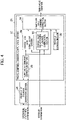
- FIG. 4 is a functional block diagram of the controller 24 in the present embodiment.
- the controller 24 in the present embodiment includes a travel combined command computation section 27 in addition to the pump/valve command generation section 26.
- the travel combined command computation section 27 corrects the pump/valve commands computed by the pump/valve command generation section 26 on the basis of operation lever information and pressure information concerning the hydraulic cylinder 13, and outputs the corrected commands to the pumps and valves.
- the travel combined command computation section 27 includes a pump/valve command correction section 28, a charge flow rate computation section 29, a charge relief valve passing flow rate computation section 30, a pump flow rate command correction section 31, and a threshold storage section 32.
- the pump/valve command correction section 28 corrects the commands for the assist switching valves 15a and 15c of the pump/valve commands upon detecting an operation of the travel operation lever 25b, and outputs the corrected pump/valve commands to the charge flow rate computation section 29, the charge relief valve passing flow rate computation section 30, and the pump flow rate command correction section 31.
- the charge flow rate computation section 29 computes a charge flow rate based on the pump/valve commands and pressure information concerning the hydraulic cylinder 13, and outputs the charge flow rate to the pump flow rate command correction section 31.
- the charge flow rate here is a flow rate obtained by subtracting the flow rate which the hydraulic cylinder 13 (4, 5, 6) delivers into the charge flow path 40 from the flow rate which the hydraulic cylinder 13 (4, 5, 6) absorbs from the charge flow path 40 (the flow rate which the hydraulic cylinders 13 (4, 5, and 6) as a whole absorb from the charge flow path 40).
- the charge relief valve passing flow rate computation section 30 computes a charge relief valve passing flow rate based on the pump/valve commands and pressure information concerning the hydraulic cylinder 13, and outputs the charge relief valve passing flow rate to the pump flow rate command correction section 31.
- the charge relief valve passing flow rate here is a flow rate discharged to the oil tank 14 through the charge relief valve 23, and is a flow rate obtained by subtracting the flow rate which the hydraulic cylinder 13 (4, 5, 6) absorbs from the charge flow path 40 from the sum of the delivery flow rate of the charge pump 10 and the flow rate which the hydraulic cylinder 13 (4, 5, 6) delivers into the charge flow path 40.
- the pump flow rate command correction section 31 corrects the delivery flow rate of the closed-circuit pump 7 of the pump/valve commands to the reduction side when the charge flow rate exceeds a threshold or when the charge relief valve passing flow rate exceeds a threshold, and outputs the corrected pump/valve command to the pumps and valves.
- the thresholds here are stored in the threshold storage section 32.
- FIG. 5 is a flow chart depicting processing in one control period of the travel combined command computation section 27. The processing will be described sequentially below.
- processing F3 it is determined whether or not a cylinder extension operation is being conducted on the basis of input information concerning a work operation lever 25a (processing F3).
- processing F4 When it is determined in the processing F3 that a cylinder extension operation is being conducted (YES), the charge flow rate is computed (processing F4).
- processing F4 it is determined whether or not the charge flow rate is equal to or less than the delivery flow rate of the charge pump 10 (processing F5).
- the delivery flow rate of the closed-circuit pump 7 driving the hydraulic cylinder 13 is restricted such that the charge flow rate becomes equal to or less than the delivery flow rate of the charge pump 10, and the flow is finished.
- processing F7 When it is determined in the processing F3 that the cylinder extension operation is not being conducted (NO), the charge relief valve passing flow rate is computed (processing F7).
- processing F8 it is determined whether or not the charge relief valve passing flow rate is equal to or less than a threshold (processing F8). A method of setting the threshold will be described later.
- the delivery flow rate of the closed-circuit pump 7 driving the hydraulic cylinder 13 is restricted such that the charge relief flow rate becomes equal to or less than the threshold, and the flow is finished.
- the controller 24 In the case of operating the work operation lever 25a and singularly operating only the hydraulic cylinder 13, the controller 24 outputs flow commands for the closed-circuit pump 7 and the open-circuit pump 8, an opening command for the switching valve 15a and a closing command for the breed-off valve 19a and drives the hydraulic cylinder 13, according to the operation amount of the work operation lever 25a.
- the delivery flow rate of the closed-circuit pump 7 be Qcp
- the delivery flow rate of the open-circuit pump 8 be Qop
- the pressure receiving area of a cap-side chamber of the hydraulic cylinder 13 be Acap
- the pressure receiving area of a rod-side chamber be Arod
- Qcp and Qop are determined such that the pump flow rate ratio (Qcp + Qop):Qcp becomes equal to the pressure receiving area ratio Acap:Arod.
- the controller 24 performs a control such that the delivery flow rate ratio of the closed-circuit pump 7 to the open-circuit pump 8 varies while keeping Qcp:Qop. In this way, at the time of driving the hydraulic cylinder 13, the closed-circuit pump 7 and the open-circuit pump 8 are used in combination.
- the controller 24 outputs flow rate commands for the open-circuit pumps 8 and 9, opening commands for the travel switching valves 15b and 15d, closing commands for the breed-off valves 19a and 19b, and opening commands for the travel flow rate control valves 17a and 17b and drives the travel hydraulic motors 16a and 1b, according to an operation amount of the travel operation lever 25b. In this way, at the time of a travel operation, only the open-circuit pumps 8 and 9 are used.
- the conventional controller 24X sets a flow rate command for the open-circuit pump 8 to 0, outputs a closing command to the travel switching valve 15b and an opening command to the breed-off valve 19a, thereafter outputs flow rate commands for the closed-circuit pump 7 and the open-circuit pump 8, an opening command for the assist switching valve 15a, and a closing command for the breed-off valve 19a, and controls the hydraulic cylinder 13 and the travel hydraulic motors 16a and 16b.
- the hydraulic cylinder 13 is operated by the closed-circuit pump 7 and the open-circuit pump 8 and, simultaneously, travel is operated by the open-circuit pump 9, whereby a combined operability is secured.
- the hydraulic cylinder 13 is operated while the travel hydraulic motors 16a and 16b are originally driven by the open-circuit pumps 8 and 9, the open-circuit pump 8 having been used for travel is used for driving the hydraulic cylinder 13.
- the pump which can be used for travel is only the open-circuit pump 9, so that traveling speed is largely lowered, and travel operability is conspicuously impaired.
- processing by a travel combined command computation section 27 provided in the controller 24 according to the present embodiment depicted in FIG. 4 is performed.
- the processing F1 of FIG. 5 it is determined whether or not a travel operation is being conducted on the basis of an operation amount of the travel operation lever 25b.
- the pump for driving the hydraulic cylinder 13 is restricted to only the closed-circuit pump 7 when it is determined in the processing F1 that a travel operation is being conducted.
- the open-circuit pumps 8 and 9 can be occupied for driving the travel hydraulic motors 16a and 16b during a travel operation, so that even if the hydraulic cylinder 13 is operated during the travel operation, the traveling speed is not lowered, and the travel operability is not impaired.
- the oil is replenished from the charge pump 10 into the flow path, where flow rate insufficiency has been generated through the check valve 20a or the check valve 20n, but, when the replenished flow rate is more than the flow rate flowing into the charge flow path 40, the pressure in the charge flow path 40 (hereinafter, charge pressure) would be lowered, this may lower the reliability such that cavitation is generated to damage the apparatus.
- the charge flow rate is computed in the processing F4 from an operation amount of the work operation lever 25a, pressure information concerning the pressure sensors 51 and 52, and the like, and it is determined in the processing F5 whether or not the charge flow rate (the flow rate which the hydraulic cylinders 13 (4, 5, 6) as a whole absorb from the charge flow path 40) is equal to or less than the charge pump delivery flow rate.
- the delivery flow rate of the closed-circuit pump 7 is restricted in the processing F6 until the charge flow rate becomes equal to or less than the charge pump delivery flow rate.
- the threshold is determined based on the pressure override characteristics of the charge relief valve 23 depicted in FIG. 6 . Specifically, the threshold is set at a value equal to or less than the charge relief valve passing flow rate Fmax when the charge pressure reaches a maximum allowable pressure Pmax. The maximum allowable pressure Pmax is determined within a range such that the fuel cost and operability are not influenced. For example, in the case where a target value of the charge pressure is 2 MPa, the threshold is set on the order of 3 MPa.
- the hydraulic excavator 100 including the travel body 101, the work device 103, the travel hydraulic motors 16a and 16b that drives the travel body 101, at least one single-rod hydraulic cylinder 13 (4, 5, 6) that drives the work device 103, the travel operation lever 25b that issues instructions on operations of the travel hydraulic motors 16a and 16b, the work operation lever 25a that issues an instruction on an operation of the single-rod hydraulic cylinder 13 (4, 5, 6), the closed-circuit pump 7 connected through closed circuit to the single-rod hydraulic cylinder 13 (4, 5, 6), the cap-side flow path 41 that connects the delivery port on one side of the closed-circuit pump 7 to the cap-side chamber 13a of the single-rod hydraulic cylinder 13 (4, 5, 6), the rod-side flow path 42 that connects the delivery port on the other side of the closed-circuit pump 7 to the rod-side chamber 13b of the single-rod hydraulic cylinder 13 (4, 5, 6), the open-circuit pumps 8 and 9, the travel flow rate control valves 17a and 17b that
- the single-rod hydraulic cylinder 13 (4, 5, 6) is restricted to be driven by only the closed-circuit pump 7 when the single-rod hydraulic cylinder 13 (4, 5, 6) is driven during a travel operation, whereby the open-circuit pumps 8 and 9 are occupied for driving the travel hydraulic motors 16a and 16b.
- the traveling speed is not lowered, so that travel operability is not impaired.
- the hydraulic excavator 100 includes the charge pump 10, the charge flow path 40 connected to the delivery port of the charge pump 10, the charge relief valve 23 provided in the charge flow path 40, the check valves 20a and 20b provided between the cap-side flow path 41 and the rod-side flow path 42 and the charge flow path 40, and the flushing valve 21 provided between the cap-side flow path 41 and the rod-side flow path 42 and the charge flow path 40, and the controller 24 corrects the delivery flow rate of the closed-circuit pump 7 such that the charge flow rate obtained by subtracting the flow rate that the single-rod hydraulic cylinder 13 (4, 5, 6) discharges into the charge flow path 40 from the flow rate which the single-rod hydraulic cylinder 13 (4, 5, 6) absorbs from the charge flow path 40 becomes equal to or less than the delivery flow rate of the charge pump 10.
- the charge pressure is restrained from being lowered, so that reliability can be prevented from being lowered due to cavitation.
- the controller 24 corrects the delivery flow rate of the closed-circuit pump 7 such that the passing flow rate through the charge relief valve 23 obtained by subtracting the flow rate which the single-rod hydraulic cylinder 13 (4, 5, 6) absorbs from the charge flow path 40 from the sum of the flow rate the single-rod hydraulic cylinder 13 (4, 5, 6) discharges into the charge flow rate 40 and the delivery flow rate of the charge pump 10 becomes equal to or less than a predetermined flow rate.
- a rise in the charge pressure is restrained, and, therefore, worsening of operability due to a lowering in thrust force of the hydraulic cylinder 13 (4, 5, 6) and worsening of fuel cost due to an increase in the load on the charge pump 10 can be prevented.
Landscapes
- Engineering & Computer Science (AREA)
- General Engineering & Computer Science (AREA)
- Mining & Mineral Resources (AREA)
- Civil Engineering (AREA)
- Structural Engineering (AREA)
- Mechanical Engineering (AREA)
- Physics & Mathematics (AREA)
- Fluid Mechanics (AREA)
- Operation Control Of Excavators (AREA)
- Fluid-Pressure Circuits (AREA)
Applications Claiming Priority (2)
| Application Number | Priority Date | Filing Date | Title |
|---|---|---|---|
| JP2019154133A JP7209602B2 (ja) | 2019-08-26 | 2019-08-26 | 建設機械 |
| PCT/JP2020/032072 WO2021039805A1 (ja) | 2019-08-26 | 2020-08-25 | 建設機械 |
Publications (2)
| Publication Number | Publication Date |
|---|---|
| EP4001666A1 true EP4001666A1 (de) | 2022-05-25 |
| EP4001666A4 EP4001666A4 (de) | 2023-07-26 |
Family
ID=74677137
Family Applications (1)
| Application Number | Title | Priority Date | Filing Date |
|---|---|---|---|
| EP20858546.3A Pending EP4001666A4 (de) | 2019-08-26 | 2020-08-25 | Baumaschine |
Country Status (5)
| Country | Link |
|---|---|
| US (1) | US11970838B2 (de) |
| EP (1) | EP4001666A4 (de) |
| JP (1) | JP7209602B2 (de) |
| CN (1) | CN114258462B (de) |
| WO (1) | WO2021039805A1 (de) |
Families Citing this family (3)
| Publication number | Priority date | Publication date | Assignee | Title |
|---|---|---|---|---|
| WO2023162684A1 (ja) * | 2022-02-24 | 2023-08-31 | 日立建機株式会社 | 作業機械 |
| JP7817007B2 (ja) * | 2022-02-24 | 2026-02-18 | 日立建機株式会社 | 作業機械 |
| JP7785567B2 (ja) * | 2022-02-24 | 2025-12-15 | 日立建機株式会社 | 建設機械 |
Family Cites Families (15)
| Publication number | Priority date | Publication date | Assignee | Title |
|---|---|---|---|---|
| JP3481674B2 (ja) * | 1994-05-31 | 2003-12-22 | 東芝機械株式会社 | 建設機械の油圧回路 |
| DE69620463T2 (de) * | 1995-05-17 | 2002-10-31 | Komatsu Ltd., Tokio/Tokyo | Hydraulischer kreislauf für hydraulisch angetriebene arbeitsfahrzeuge |
| JPH11141504A (ja) * | 1997-11-11 | 1999-05-25 | Daikin Ind Ltd | 油圧回路装置 |
| JP5461234B2 (ja) * | 2010-02-26 | 2014-04-02 | カヤバ工業株式会社 | 建設機械の制御装置 |
| US9080310B2 (en) * | 2011-10-21 | 2015-07-14 | Caterpillar Inc. | Closed-loop hydraulic system having regeneration configuration |
| US9683588B2 (en) * | 2012-01-31 | 2017-06-20 | Hitachi Construction Machinery Co., Ltd. | Hydraulic closed circuit system |
| JP2013245787A (ja) | 2012-05-28 | 2013-12-09 | Hitachi Constr Mach Co Ltd | 作業機械の駆動装置 |
| CN104903595B (zh) * | 2013-01-08 | 2017-03-08 | 日立建机株式会社 | 工作机械的液压系统 |
| CN203362659U (zh) * | 2013-08-05 | 2013-12-25 | 艾迪士径向钻井(烟台)有限公司 | 一种负载敏感控制的连续管液压系统 |
| JP6134614B2 (ja) * | 2013-09-02 | 2017-05-24 | 日立建機株式会社 | 作業機械の駆動装置 |
| JP6285787B2 (ja) | 2014-04-14 | 2018-02-28 | 日立建機株式会社 | 油圧駆動装置 |
| JP6298716B2 (ja) | 2014-05-30 | 2018-03-20 | 日立建機株式会社 | 作業機械 |
| JP6328548B2 (ja) * | 2014-12-23 | 2018-05-23 | 日立建機株式会社 | 作業機械 |
| JP6539556B2 (ja) | 2015-09-18 | 2019-07-03 | 株式会社神戸製鋼所 | 作業機械の油圧駆動装置 |
| JP6654521B2 (ja) * | 2016-07-15 | 2020-02-26 | 日立建機株式会社 | 建設機械 |
-
2019
- 2019-08-26 JP JP2019154133A patent/JP7209602B2/ja active Active
-
2020
- 2020-08-25 EP EP20858546.3A patent/EP4001666A4/de active Pending
- 2020-08-25 WO PCT/JP2020/032072 patent/WO2021039805A1/ja not_active Ceased
- 2020-08-25 CN CN202080058880.1A patent/CN114258462B/zh active Active
- 2020-08-25 US US17/637,225 patent/US11970838B2/en active Active
Also Published As
| Publication number | Publication date |
|---|---|
| EP4001666A4 (de) | 2023-07-26 |
| JP7209602B2 (ja) | 2023-01-20 |
| JP2021032361A (ja) | 2021-03-01 |
| CN114258462B (zh) | 2024-01-05 |
| US11970838B2 (en) | 2024-04-30 |
| CN114258462A (zh) | 2022-03-29 |
| US20230349132A1 (en) | 2023-11-02 |
| WO2021039805A1 (ja) | 2021-03-04 |
Similar Documents
| Publication | Publication Date | Title |
|---|---|---|
| US9695842B2 (en) | Hydraulic drive system | |
| US10995475B2 (en) | Construction machine | |
| US9624647B2 (en) | Slewing-type working machine | |
| US10227997B2 (en) | Hydraulic drive system for work machine | |
| EP3203088A1 (de) | Hydraulisches antriebssystem einer industriemaschine | |
| US11970838B2 (en) | Construction machine | |
| US10767674B2 (en) | Construction machine | |
| US10167880B2 (en) | Shovel and method of controlling shovel | |
| KR102456137B1 (ko) | 쇼벨 | |
| KR101747519B1 (ko) | 하이브리드식 건설 기계 | |
| WO2021192389A1 (ja) | 作業機械 | |
| JP6814309B2 (ja) | 建設機械 | |
| CN111373159A (zh) | 工程机械 | |
| US10914053B2 (en) | Work machine | |
| KR20120026199A (ko) | 고지대 또는 한냉 지역에서 엔진시동을 제어하는 건설기계용 유량제어장치 | |
| JP2013044399A (ja) | 油圧駆動システム | |
| JP2020051482A (ja) | 建設機械の油圧制御システム | |
| JP6763326B2 (ja) | 油圧回路 |
Legal Events
| Date | Code | Title | Description |
|---|---|---|---|
| STAA | Information on the status of an ep patent application or granted ep patent |
Free format text: STATUS: THE INTERNATIONAL PUBLICATION HAS BEEN MADE |
|
| PUAI | Public reference made under article 153(3) epc to a published international application that has entered the european phase |
Free format text: ORIGINAL CODE: 0009012 |
|
| STAA | Information on the status of an ep patent application or granted ep patent |
Free format text: STATUS: REQUEST FOR EXAMINATION WAS MADE |
|
| 17P | Request for examination filed |
Effective date: 20220221 |
|
| AK | Designated contracting states |
Kind code of ref document: A1 Designated state(s): AL AT BE BG CH CY CZ DE DK EE ES FI FR GB GR HR HU IE IS IT LI LT LU LV MC MK MT NL NO PL PT RO RS SE SI SK SM TR |
|
| DAV | Request for validation of the european patent (deleted) | ||
| DAX | Request for extension of the european patent (deleted) | ||
| A4 | Supplementary search report drawn up and despatched |
Effective date: 20230628 |
|
| RIC1 | Information provided on ipc code assigned before grant |
Ipc: F15B 11/08 20060101ALI20230622BHEP Ipc: E02F 9/22 20060101ALI20230622BHEP Ipc: F15B 11/02 20060101AFI20230622BHEP |