EP4001674B1 - Halterung und verfahren dafür - Google Patents
Halterung und verfahren dafür Download PDFInfo
- Publication number
- EP4001674B1 EP4001674B1 EP21204319.4A EP21204319A EP4001674B1 EP 4001674 B1 EP4001674 B1 EP 4001674B1 EP 21204319 A EP21204319 A EP 21204319A EP 4001674 B1 EP4001674 B1 EP 4001674B1
- Authority
- EP
- European Patent Office
- Prior art keywords
- drywall
- support mount
- head portion
- self
- flanged head
- Prior art date
- Legal status (The legal status is an assumption and is not a legal conclusion. Google has not performed a legal analysis and makes no representation as to the accuracy of the status listed.)
- Active
Links
Images


Classifications
-
- F—MECHANICAL ENGINEERING; LIGHTING; HEATING; WEAPONS; BLASTING
- F16—ENGINEERING ELEMENTS AND UNITS; GENERAL MEASURES FOR PRODUCING AND MAINTAINING EFFECTIVE FUNCTIONING OF MACHINES OR INSTALLATIONS; THERMAL INSULATION IN GENERAL
- F16B—DEVICES FOR FASTENING OR SECURING CONSTRUCTIONAL ELEMENTS OR MACHINE PARTS TOGETHER, e.g. NAILS, BOLTS, CIRCLIPS, CLAMPS, CLIPS OR WEDGES; JOINTS OR JOINTING
- F16B25/00—Screws that cut thread in the body into which they are screwed, e.g. wood screws
- F16B25/001—Screws that cut thread in the body into which they are screwed, e.g. wood screws characterised by the material of the body into which the screw is screwed
- F16B25/0026—Screws that cut thread in the body into which they are screwed, e.g. wood screws characterised by the material of the body into which the screw is screwed the material being a hard non-organic material, e.g. stone, concrete or drywall
-
- F—MECHANICAL ENGINEERING; LIGHTING; HEATING; WEAPONS; BLASTING
- F16—ENGINEERING ELEMENTS AND UNITS; GENERAL MEASURES FOR PRODUCING AND MAINTAINING EFFECTIVE FUNCTIONING OF MACHINES OR INSTALLATIONS; THERMAL INSULATION IN GENERAL
- F16B—DEVICES FOR FASTENING OR SECURING CONSTRUCTIONAL ELEMENTS OR MACHINE PARTS TOGETHER, e.g. NAILS, BOLTS, CIRCLIPS, CLAMPS, CLIPS OR WEDGES; JOINTS OR JOINTING
- F16B13/00—Dowels or other devices fastened in walls or the like by inserting them in holes made therein for that purpose
- F16B13/002—Dowels or other devices fastened in walls or the like by inserting them in holes made therein for that purpose self-cutting
-
- F—MECHANICAL ENGINEERING; LIGHTING; HEATING; WEAPONS; BLASTING
- F16—ENGINEERING ELEMENTS AND UNITS; GENERAL MEASURES FOR PRODUCING AND MAINTAINING EFFECTIVE FUNCTIONING OF MACHINES OR INSTALLATIONS; THERMAL INSULATION IN GENERAL
- F16B—DEVICES FOR FASTENING OR SECURING CONSTRUCTIONAL ELEMENTS OR MACHINE PARTS TOGETHER, e.g. NAILS, BOLTS, CIRCLIPS, CLAMPS, CLIPS OR WEDGES; JOINTS OR JOINTING
- F16B2200/00—Constructional details of connections not covered for in other groups of this subclass
- F16B2200/83—Use of a magnetic material
Definitions
- the present invention relates to a fastener for mounting a drywall structure to a surface, in particular for mounting drywall sheet to a metal structure.
- a method of fixing a drywall structure to a metal structure is also disclosed.
- Drywall structures are known as means to fabricate a wall during building construction. Installation of drywall structures produces wall- or ceiling surfaces more quickly than traditional lath and plaster.
- drywall structure includes sheets, panels or boards in the form of plasterboard, wallboard, sheet rock, buster board, custard board, as well as, boarding or panels formed from gyprock or gypsum.
- Drywall structures are typically installed by fixing the drywall structure to a surface, e.g. a metal surface of a support frame, using appropriate fasteners, such as, for example, screws or fixings.
- each fastener is driven from the outer surface of the drywall structure through and into the metal surface of the support frame (or any other support surface).
- a drywall structure normally extends over the entire height of a room (i.e. between the floor and the ceiling), and a series of drywall panels are lined up to cover the entire wall or ceiling surface.
- a panel is held in a fixing position to the support surface by at least one first installer, while a second installer drives the fasteners into the panels and support surface.
- first installer drives the fasteners into the panels and support surface.
- second installer drives the fasteners into the panels and support surface.
- drywall panels can be relatively large and cumbersome, so handling the drywall structures can be difficult to coordinate.
- a first installer at least one second installer is required to drive a requisite number of fasteners through the panel and into the support surface (e.g. metal strut or metal frame).
- the support surface e.g. metal strut or metal frame.
- holding a large panel in steady a precise position can be tiring and unsafe, because the installer holding the panel may fatigue and the panel may fall over.
- each drywall panel (of many) is typically held manually by an installer to then be manoeuvred into the correct fixing position. Further, the installation process requires continuous coordinating between the at least two installers, thus, making the installation laborious and time consuming.
- a further object of the invention is to provide an apparatus, as well as, a method that provides for an improved accuracy when positioning and fixing drywall panels on a surface.
- a self-drilling support mount for a drywall structure according to claim 1, comprising:
- said at least one magnetic attachment member may be provided at an outer surface of said flanged head portion.
- drywall panels can be easily equipped with an interim support mount allowing a single installer to simply drive the support mounts into the drywall panel at suitable locations, to then simply attach (via the magnets) the drywall panel to a metal frame structure and slidably move the panel into the correct fixing position on the metal frame structure without the need of any help from at least one second installer.
- the drywall panel can be installed quicker and more accurately, with a reduced risk of the drywall panel accidentally falling down during installation.
- said magnetic attachment member may be embeddingly coupled to said flanged head portion, so as to be flush with said outer surface of said flanged head portion.
- said magnetic attachment member may be replaceably mounted to said flanged head portion.
- the fastener may be conveniently and cost effectively repaired should the magnetic attachment member become damaged or lost.
- said outer surface of said flanged head portion may include an axial recess forming an inset drive screw socket configured for screwing the self-drilling support mount onto said drywall structure.
- said magnetic attachment member may be arranged coaxial with said axial recess.
- said magnetic attachment member may be a separate washer configured to be operably coupled with said substantially cylindrical body of said support mount.
- This provides the advantage of using a simple washer construction that can be coupled with the support mount so as to provide a magnetic field strong enough the attach the support mount and drywall structure to the metal surface.
- the magnetic attachment member is "wedged in” between the flanged head portion and the drywall surface, wherein, the flanged head portion and magnetic washer are preferably embedded (i.e. "sunk") into the drywall so as to provide the outer surface of the flanged head portion flush with the outer surface of the drywall , when installed.
- said anchor portion may be configured to be rotatably driven into the drywall structure so as to stoppingly engage said flanged head portion with the drywall structure.
- a support mount 100 for a drywall structure has a substantially cylindrical body including a flanged head portion 140 at a proximal end (proximal relative to the user when installing the fastener), and an anchor portion 120 extending away from the flanged head portion 140 towards a distal end.
- the anchor portion 120 extends in the direction along a longitudinal axis 160 and is provided with an external thread 125.
- the flanged head portion 140 includes a magnetic attachment member 142 provided at the head portion 140 so as to be flush with an outer surface and operably face away from the distal end.
- the magnetic attachment member 142 is adapted to slidably movably attach to any suitable metal structure when fastened to the drywall structure, i.e. the magnetic force is sufficient to hold (in combination with the other magnetic attachment members 142 from other mounts 100) the drywall panel securely attached to the metal support frame while allowing the installer to shift (or slide) the drywall panel on the metal surface.
- the anchor portion 120 includes a cylindrical outer surface onto which is provided the external thread 125.
- the external thread 125 extends from the flanged head portion 140 to the distal end of the anchor portion 120.
- the outer thread 125 is configured to allow a user to rotatably drive the support mount 100 into a drywall structure.
- the flanged head portion 140 includes an upper surface extending radially from the longitudinal axis 160.
- An axial recess 144 is provided into the head portion 140, extending in a direction towards the distal tip of the anchor portion 120.
- the axial recess 144 is coaxially in line with the tubular body of the anchor portion 120.
- a drive screw socket configured to receive a suitable screwdriver tool (not shown). This enables the user / installer to rotate the support mount 100 in order to drive the threaded anchor portion 120 into the drywall panel.
- the magnetic attachment member 142 of the example shown in Figure 1 is annular with an axial opening therethrough.
- the magnetic attachment member 142 is embedded into the flanged head portion 140 so that the magnetic attachment member's upper face sits flush with the upper surface of the flanged head portion 140.
- the axial opening of the magnetic attachment member 142 is coaxial with the axial recess 144 and sized so that the inner wall of the axial opening forms an upper portion of the axial recess 144.
- the external thread 125 is provided as a wide blade coarse thread, so that the support mount 100 is self-drilling.
- the external thread 125 is configured so that, in use, the external thread 125 is able to excavate an orifice within a drywall structure 200 (see Figure 2 ) into which the anchor portion 120 is driven by a user.
- the external thread 125 is configured in such a way that, with the distal end of the anchor portion 120 engaged with the surface of a drywall structure 200, when a user rotates and applies downward pressure to the support mount 100, then the external thread 125 punctures through the surface (e.g. 210).
- each support mount 100 is fixed with its longitudinal axis 160 substantially orthogonal to the first surface 210. Furthermore, each support mount 100 is fixed so that the upper surface of the flanged head portion 140 is flush with the first surface 210 of the drywall structure 200. Each magnetic attachment member 142 is thus positioned substantially flush and in parallel with the first surface 210.
- the support mount 100 has an axial length that is less than the thickness of the drywall structure 200.
- the anchor portion 120 resides wholly within the body of the drywall structure 200 (see Figures 3 and 4 , described below)and the distal tip does not protrude through the drywall structure 200.
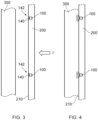
- Figures 3 to 4 show cross-sectional side views of the drywall structure 200 with two embedded support mounts 100 before and after attachment to a metal structure 300 (e.g. a metal frame).
- the metal structure 300 may be a part of a larger frame which forms a support for multiple drywall structures in order to fabricate the internal wall or ceiling of a building.
- the drywall structure 200 is simply positioned so that the first surface 210 and embedded support mounts 100 are facing the metal structure 300. In this position, the drywall structure 200 is ready for magnetic attachment to the metal structure 300.
- the drywall structure 200 may be positioned by an installer with only approximate alignment relative to a fixing position.
- the magnetic attachment members 142 of respective support mounts 100 are then brought into engagement with the metal structure 300 by the installer moving the drywall structure 200 in the general direction indicated by the arrow F .
- Each magnetic attachment member 142 engages the metal structure 300 so as to attach the drywall structure 200 to the metal structure 300, as shown in Figure 4 .
- the attracting force to the metal structure 300 provided by of the magnetic attachment members 142 is sufficient to at least temporarily fix the drywall structure 200 to the metal structure 300. That is, the drywall structure 200 is attached and held on the metal structure 300 by the support mounts 100 without additional support, for example, from an installer.
- the installer will be able to slidably move the drywall structure 200 relative to the metal structure 300 without detachment from the metal structure 300.
- the support mounts 100 remain engaged with the metal structure 300 as the drywall structure 200 is moved over the surface of the metal structure 300 into a desired fixing position.
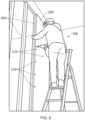
- Figure 5 shows an example illustration of an installer 350 fixing a drywall structure 200' to a metal structure 300'.
- the drywall structure 200' is shown aligned in the desired fixing position.
- the drywall structure 200' is secured to the metal structure 300' using suitable screw fasteners 310 inserted through said drywall structure 200' and into the metal structure 300'.
- the screw fasteners 310 may be any suitable fastener configured to screw through the drywall structure 200' and into the metal frame structure 300'. By securing the drywall structure 200' to the metal structure 300' the drywall structure is rendered immobile relative to the metal structure 300'.
- Figure 6 shows a flow chart of an example method 400 suitable for fixing the drywall structure 200 to the metal structure 300.
- the method 400 starts by providing 410 at least one (but preferably one or more for each corner of the drywall panel 200) self-drilling interim support mount 100, such as the support mount 100 described with reference to Figures 1 to 5 .
- the anchor portion 120 of the support mount 100 is then rotatably driven 420 into the drywall structure 200 until the flanged head portion 140 of the support mount 100 stoppingly engages with the drywall structure 200.
- the magnetic attachment member of the support mount 100 is then engaged 430 with the metal frame structure 300 so as to attach the drywall structure 200 to the metal frame structure 300.
- the drywall structure 200 is then moved (slid) into a desired fixing position (if required) 440.
- a fastener e.g. a suitable screw fastener
- the magnetic attachment member is arranged to directly contact the metal structure when brought into engagement.
- a cover may be provided on the magnetic attachment member in order to provide protection.
- the cover may be, for example, a thermoplastic coating.
- the flanged head portion may include a reduced friction element.
- a surface or portion of a surface that engages with the metal structure may be modified through suitable etching, patterning, embossing, debossing or a spark finish.
- the cover itself may be formed from, or contain a proportion of, low friction material such as PTFE or similar.
- the flanged head portion 140 of the support mount 100 engages and couples a magnetic attachment member 142 to the drywall structure 200.
- the support mount 100 may couple a magnetic strip or washer to the drywall structure 200 as it is driven into the drywall structure 200.
- the magnetic attachment member 142 thus movably slidably attaches the drywall structure 200 to the metal structure 300 in the same manner as a magnetic attachment member of a flanged head portion.
- the magnetic attachment member may simply be provided as a washer configured to operably couple with the thread and head portion of the support mount.
- the magnetic washer may simply be slid over the thread portion into contact with a lower surface of the flanged head portion and then embedded into the drywall structure.
- the material used for the flanged head portion is suitable to promote the magnetic field of the washer so as to attach the support mount to a metal surface during use.
- a method of fixing the drywall structure to a metal structure may include a user engaging a plurality of support mounts 100 to a drywall structure 200 and attaching a proportion of the plurality of support mounts 100 to the metal surface to slidably movably attach the drywall structure relative to the metal structure 300.
- a corresponding proportion of support mounts 100 may be disengaged from the metal structure 300 as it is moved to its desired fixing position.
- the disengaged support mounts 100 may then be attached to the metal structure before more permanent fasteners are inserted.
- an alternative method may include the user temporarily attaching several drywall structures to a metal structure using respective support mounts 100, then slidably moving each drywall structure 200 relative to the metal structure 300 to a respective fixing position. Once each drywall structure 200 is in its respective fixing position then at least one fastener is inserted into each drywall structure 200, thereby securing each drywall structure 200 to the metal structure 300 in their respective fixing position.
Landscapes
- Engineering & Computer Science (AREA)
- General Engineering & Computer Science (AREA)
- Mechanical Engineering (AREA)
- Connection Of Plates (AREA)
Claims (9)
- Selbstbohrende Stützhalterung (100) für eine Trockenbaustruktur (200), aufweisend:einen im Wesentlichen zylindrischen Körper, der einen Flanschkopfabschnitt (140) an einem proximalen Ende und einen mit Außengewinde versehenen Ankerabschnitt (125), der sich von dem Flanschkopfabschnitt weg entlang einer Längsmittelachse (160) des zylindrischen Körpers zu einem distalen Ende erstreckt, aufweist,wobei der Flanschkopfabschnitt (140) mindestens ein magnetisches Befestigungselement (142) aufweist, das dazu ausgelegt ist, die Stützhalterung (100) gleitend bewegbar an einer Metallstruktur zu befestigen, wenn der Flanschkopfabschnitt in Kontakt mit der Trockenbaustruktur ist,dadurch gekennzeichnet, dass das mindestens eine magnetische Befestigungselement (142) eine im Wesentlichen ringförmige Form mit einer axialen Öffnung dadurch aufweist.
- Selbstbohrende Stützhalterung nach Anspruch 1, wobei das magnetische Befestigungselement (142) an einer Außenfläche des Flanschkopfabschnitts vorgesehen ist.
- Selbstbohrende Stützhalterung nach einem der vorhergehenden Ansprüche, wobei das magnetische Befestigungselement (142) in eingebetteter Form derart mit dem Flanschkopfabschnitt gekoppelt ist, dass es mit der Außenfläche des Flanschkopfabschnitts bündig ist.
- Selbstbohrende Stützhalterung (100) nach einem der vorhergehenden Ansprüche, wobei das magnetische Befestigungselement (142) austauschbar an dem Flanschkopfabschnitt (140) angebracht ist.
- Selbstbohrende Stützhalterung (100) nach einem der Ansprüche 2 bis 4, wobei die Außenfläche des Flanschkopfabschnitts eine axiale Ausnehmung aufweist, die eine Einsatz-Antriebsschraubenbuchse bildet, die es ermöglicht, die selbstbohrende Stützhalterung auf die Trockenbaustruktur (200) zu schrauben.
- Selbstbohrende Stützhalterung nach Anspruch 5, wobei das magnetische Befestigungselement koaxial zu der axialen Ausnehmung angeordnet ist.
- Selbstbohrende Stützhalterung nach Anspruch 1, wobei das magnetische Befestigungselement eine Unterlegscheibe ist, die eingerichtet ist, mit dem im Wesentlichen zylindrischen Körper der Stützhalterung funktionell gekoppelt zu werden.
- Selbstbohrende Stützhalterung nach einem der vorhergehenden Ansprüche, wobei der Ankerabschnitt (120) eingerichtet ist, rotatorisch in die Trockenbaustruktur (200) eingetrieben zu werden, um den Flanschkopfabschnitt mit der Trockenbaustruktur sperrend in Eingriff zu bringen.
- Verfahren zum Befestigen einer Trockenbaustruktur an einer Metallstruktur, die folgenden Schritte aufweisend:(a) Bereitstellen mindestens einer selbstbohrenden Stützhalterung nach einem der vorhergehenden Ansprüche;(b) rotatorisches Eintreiben eines Ankerabschnitts der mindestens einen selbstbohrenden Stützhalterung in die Trockenbaustruktur, bis ein Flanschkopfabschnitt mit der Trockenbaustruktur sperrend in Eingriff tritt;(c) Ineingriffbringen eines magnetischen Befestigungselements der mindestens einen an der Trockenbaustruktur befestigten selbstbohrenden Stützhalterung mit einer Metallstruktur, um die Trockenbaustruktur selektiv gleitend bewegbar an der Metallträgerstruktur zu befestigen;(d) gleitendes Bewegen der Trockenbaustruktur in eine gewünschte Befestigungsposition relativ zu der Metallstruktur;(e) Einführen mindestens eines Befestigungselements durch die Trockenbaustruktur und in die Metallstruktur, um die Trockenbaustruktur an der Metallstruktur zu befestigen.
Applications Claiming Priority (1)
| Application Number | Priority Date | Filing Date | Title |
|---|---|---|---|
| EP20208005 | 2020-11-17 |
Publications (2)
| Publication Number | Publication Date |
|---|---|
| EP4001674A1 EP4001674A1 (de) | 2022-05-25 |
| EP4001674B1 true EP4001674B1 (de) | 2025-06-25 |
Family
ID=73455574
Family Applications (1)
| Application Number | Title | Priority Date | Filing Date |
|---|---|---|---|
| EP21204319.4A Active EP4001674B1 (de) | 2020-11-17 | 2021-10-22 | Halterung und verfahren dafür |
Country Status (1)
| Country | Link |
|---|---|
| EP (1) | EP4001674B1 (de) |
Family Cites Families (3)
| Publication number | Priority date | Publication date | Assignee | Title |
|---|---|---|---|---|
| JPS5234357U (de) * | 1975-09-01 | 1977-03-10 | ||
| AU2007290914A1 (en) * | 2006-08-29 | 2008-03-06 | Johanasson, Patrick | Method and means to assemble a building board on a support |
| DE202010016602U1 (de) * | 2010-12-15 | 2011-09-23 | Erich Sorg | Magnetdübel |
-
2021
- 2021-10-22 EP EP21204319.4A patent/EP4001674B1/de active Active
Also Published As
| Publication number | Publication date |
|---|---|
| EP4001674A1 (de) | 2022-05-25 |
Similar Documents
| Publication | Publication Date | Title |
|---|---|---|
| US7771094B2 (en) | Mounting bracket for electrical junction box, luminaire or the like | |
| US5012624A (en) | Method and apparatus for installing wire anchors for suspended ceilings | |
| US5014476A (en) | Multicomponent panel system and method as assembly | |
| US9303669B2 (en) | Wall fastener and methods for its use | |
| US4659051A (en) | Hanger assembly | |
| US5168781A (en) | Drive socket | |
| US8166624B2 (en) | Linearly extendible impact anchor driving pole and anchor system | |
| KR20180100960A (ko) | 내진용 슬라이딩 고정클립 및 이를 이용한 외장재의 시공방법 | |
| US6161824A (en) | Wallboard installation facilitating tool | |
| KR101879276B1 (ko) | 고정수단 | |
| US20130031771A1 (en) | Duplex Toggle Bolt Assembly | |
| EP4001674B1 (de) | Halterung und verfahren dafür | |
| CN109425089A (zh) | 风口安装结构、室内机及空调机组 | |
| US9447589B2 (en) | Crown molding framing assembly | |
| CN110886454B (zh) | 一种调平结构及其使用方法 | |
| US11253070B2 (en) | Drywall kit | |
| EP3382214B1 (de) | Befestigung, kit und verfahren | |
| US3214127A (en) | Hanger for a suspended ceiling | |
| EP3824146A1 (de) | Systeme und verfahren für ein kombinationswerkzeug, das mit einem verankerungssystem verwendet wird | |
| JP2024538363A (ja) | ファサードパネル留め付けシステム及びファサードパネルを支持体に留め付ける方法 | |
| US20200332514A1 (en) | Rapid interior wall layout components and methods | |
| JPH0334423Y2 (de) | ||
| US20090078443A1 (en) | Ceiling fan mounting base | |
| CN213626412U (zh) | 板件连接组件及板件连接结构 | |
| JP3004639U (ja) | 壁材取付け下地構造 |
Legal Events
| Date | Code | Title | Description |
|---|---|---|---|
| PUAI | Public reference made under article 153(3) epc to a published international application that has entered the european phase |
Free format text: ORIGINAL CODE: 0009012 |
|
| STAA | Information on the status of an ep patent application or granted ep patent |
Free format text: STATUS: THE APPLICATION HAS BEEN PUBLISHED |
|
| AK | Designated contracting states |
Kind code of ref document: A1 Designated state(s): AL AT BE BG CH CY CZ DE DK EE ES FI FR GB GR HR HU IE IS IT LI LT LU LV MC MK MT NL NO PL PT RO RS SE SI SK SM TR |
|
| STAA | Information on the status of an ep patent application or granted ep patent |
Free format text: STATUS: REQUEST FOR EXAMINATION WAS MADE |
|
| 17P | Request for examination filed |
Effective date: 20221121 |
|
| RBV | Designated contracting states (corrected) |
Designated state(s): AL AT BE BG CH CY CZ DE DK EE ES FI FR GB GR HR HU IE IS IT LI LT LU LV MC MK MT NL NO PL PT RO RS SE SI SK SM TR |
|
| STAA | Information on the status of an ep patent application or granted ep patent |
Free format text: STATUS: EXAMINATION IS IN PROGRESS |
|
| 17Q | First examination report despatched |
Effective date: 20231018 |
|
| GRAP | Despatch of communication of intention to grant a patent |
Free format text: ORIGINAL CODE: EPIDOSNIGR1 |
|
| STAA | Information on the status of an ep patent application or granted ep patent |
Free format text: STATUS: GRANT OF PATENT IS INTENDED |
|
| RIC1 | Information provided on ipc code assigned before grant |
Ipc: F16B 1/00 20060101ALN20250123BHEP Ipc: F16B 25/00 20060101ALI20250123BHEP Ipc: F16B 13/00 20060101AFI20250123BHEP |
|
| INTG | Intention to grant announced |
Effective date: 20250212 |
|
| P01 | Opt-out of the competence of the unified patent court (upc) registered |
Free format text: CASE NUMBER: APP_12212/2025 Effective date: 20250312 |
|
| GRAS | Grant fee paid |
Free format text: ORIGINAL CODE: EPIDOSNIGR3 |
|
| GRAA | (expected) grant |
Free format text: ORIGINAL CODE: 0009210 |
|
| STAA | Information on the status of an ep patent application or granted ep patent |
Free format text: STATUS: THE PATENT HAS BEEN GRANTED |
|
| AK | Designated contracting states |
Kind code of ref document: B1 Designated state(s): AL AT BE BG CH CY CZ DE DK EE ES FI FR GB GR HR HU IE IS IT LI LT LU LV MC MK MT NL NO PL PT RO RS SE SI SK SM TR |
|
| REG | Reference to a national code |
Ref country code: GB Ref legal event code: FG4D |
|
| REG | Reference to a national code |
Ref country code: CH Ref legal event code: EP |
|
| REG | Reference to a national code |
Ref country code: DE Ref legal event code: R096 Ref document number: 602021032745 Country of ref document: DE |
|
| REG | Reference to a national code |
Ref country code: CH Ref legal event code: EP |
|
| REG | Reference to a national code |
Ref country code: IE Ref legal event code: FG4D |
|
| PG25 | Lapsed in a contracting state [announced via postgrant information from national office to epo] |
Ref country code: FI Free format text: LAPSE BECAUSE OF FAILURE TO SUBMIT A TRANSLATION OF THE DESCRIPTION OR TO PAY THE FEE WITHIN THE PRESCRIBED TIME-LIMIT Effective date: 20250625 |
|
| REG | Reference to a national code |
Ref country code: LT Ref legal event code: MG9D |
|
| PG25 | Lapsed in a contracting state [announced via postgrant information from national office to epo] |
Ref country code: NO Free format text: LAPSE BECAUSE OF FAILURE TO SUBMIT A TRANSLATION OF THE DESCRIPTION OR TO PAY THE FEE WITHIN THE PRESCRIBED TIME-LIMIT Effective date: 20250925 Ref country code: GR Free format text: LAPSE BECAUSE OF FAILURE TO SUBMIT A TRANSLATION OF THE DESCRIPTION OR TO PAY THE FEE WITHIN THE PRESCRIBED TIME-LIMIT Effective date: 20250926 |
|
| PG25 | Lapsed in a contracting state [announced via postgrant information from national office to epo] |
Ref country code: BG Free format text: LAPSE BECAUSE OF FAILURE TO SUBMIT A TRANSLATION OF THE DESCRIPTION OR TO PAY THE FEE WITHIN THE PRESCRIBED TIME-LIMIT Effective date: 20250625 |
|
| PG25 | Lapsed in a contracting state [announced via postgrant information from national office to epo] |
Ref country code: HR Free format text: LAPSE BECAUSE OF FAILURE TO SUBMIT A TRANSLATION OF THE DESCRIPTION OR TO PAY THE FEE WITHIN THE PRESCRIBED TIME-LIMIT Effective date: 20250625 |
|
| PG25 | Lapsed in a contracting state [announced via postgrant information from national office to epo] |
Ref country code: RS Free format text: LAPSE BECAUSE OF FAILURE TO SUBMIT A TRANSLATION OF THE DESCRIPTION OR TO PAY THE FEE WITHIN THE PRESCRIBED TIME-LIMIT Effective date: 20250925 |
|
| PG25 | Lapsed in a contracting state [announced via postgrant information from national office to epo] |
Ref country code: LV Free format text: LAPSE BECAUSE OF FAILURE TO SUBMIT A TRANSLATION OF THE DESCRIPTION OR TO PAY THE FEE WITHIN THE PRESCRIBED TIME-LIMIT Effective date: 20250625 |
|
| REG | Reference to a national code |
Ref country code: NL Ref legal event code: MP Effective date: 20250625 |
|
| PG25 | Lapsed in a contracting state [announced via postgrant information from national office to epo] |
Ref country code: NL Free format text: LAPSE BECAUSE OF FAILURE TO SUBMIT A TRANSLATION OF THE DESCRIPTION OR TO PAY THE FEE WITHIN THE PRESCRIBED TIME-LIMIT Effective date: 20250625 |
|
| PG25 | Lapsed in a contracting state [announced via postgrant information from national office to epo] |
Ref country code: PT Free format text: LAPSE BECAUSE OF FAILURE TO SUBMIT A TRANSLATION OF THE DESCRIPTION OR TO PAY THE FEE WITHIN THE PRESCRIBED TIME-LIMIT Effective date: 20251027 |
|
| REG | Reference to a national code |
Ref country code: AT Ref legal event code: MK05 Ref document number: 1806695 Country of ref document: AT Kind code of ref document: T Effective date: 20250625 |
|
| PG25 | Lapsed in a contracting state [announced via postgrant information from national office to epo] |
Ref country code: IS Free format text: LAPSE BECAUSE OF FAILURE TO SUBMIT A TRANSLATION OF THE DESCRIPTION OR TO PAY THE FEE WITHIN THE PRESCRIBED TIME-LIMIT Effective date: 20251025 |
|
| PG25 | Lapsed in a contracting state [announced via postgrant information from national office to epo] |
Ref country code: AT Free format text: LAPSE BECAUSE OF FAILURE TO SUBMIT A TRANSLATION OF THE DESCRIPTION OR TO PAY THE FEE WITHIN THE PRESCRIBED TIME-LIMIT Effective date: 20250625 Ref country code: SM Free format text: LAPSE BECAUSE OF FAILURE TO SUBMIT A TRANSLATION OF THE DESCRIPTION OR TO PAY THE FEE WITHIN THE PRESCRIBED TIME-LIMIT Effective date: 20250625 |
|
| PG25 | Lapsed in a contracting state [announced via postgrant information from national office to epo] |
Ref country code: CZ Free format text: LAPSE BECAUSE OF FAILURE TO SUBMIT A TRANSLATION OF THE DESCRIPTION OR TO PAY THE FEE WITHIN THE PRESCRIBED TIME-LIMIT Effective date: 20250625 |
|
| PG25 | Lapsed in a contracting state [announced via postgrant information from national office to epo] |
Ref country code: PL Free format text: LAPSE BECAUSE OF FAILURE TO SUBMIT A TRANSLATION OF THE DESCRIPTION OR TO PAY THE FEE WITHIN THE PRESCRIBED TIME-LIMIT Effective date: 20250625 |
|
| PG25 | Lapsed in a contracting state [announced via postgrant information from national office to epo] |
Ref country code: EE Free format text: LAPSE BECAUSE OF FAILURE TO SUBMIT A TRANSLATION OF THE DESCRIPTION OR TO PAY THE FEE WITHIN THE PRESCRIBED TIME-LIMIT Effective date: 20250625 |
|
| PG25 | Lapsed in a contracting state [announced via postgrant information from national office to epo] |
Ref country code: SK Free format text: LAPSE BECAUSE OF FAILURE TO SUBMIT A TRANSLATION OF THE DESCRIPTION OR TO PAY THE FEE WITHIN THE PRESCRIBED TIME-LIMIT Effective date: 20250625 |
|
| PG25 | Lapsed in a contracting state [announced via postgrant information from national office to epo] |
Ref country code: ES Free format text: LAPSE BECAUSE OF FAILURE TO SUBMIT A TRANSLATION OF THE DESCRIPTION OR TO PAY THE FEE WITHIN THE PRESCRIBED TIME-LIMIT Effective date: 20250625 |
|
| PG25 | Lapsed in a contracting state [announced via postgrant information from national office to epo] |
Ref country code: RO Free format text: LAPSE BECAUSE OF FAILURE TO SUBMIT A TRANSLATION OF THE DESCRIPTION OR TO PAY THE FEE WITHIN THE PRESCRIBED TIME-LIMIT Effective date: 20250625 |
|
| PG25 | Lapsed in a contracting state [announced via postgrant information from national office to epo] |
Ref country code: DK Free format text: LAPSE BECAUSE OF FAILURE TO SUBMIT A TRANSLATION OF THE DESCRIPTION OR TO PAY THE FEE WITHIN THE PRESCRIBED TIME-LIMIT Effective date: 20250625 |
|
| PG25 | Lapsed in a contracting state [announced via postgrant information from national office to epo] |
Ref country code: IT Free format text: LAPSE BECAUSE OF FAILURE TO SUBMIT A TRANSLATION OF THE DESCRIPTION OR TO PAY THE FEE WITHIN THE PRESCRIBED TIME-LIMIT Effective date: 20250625 |
|
| PLBE | No opposition filed within time limit |
Free format text: ORIGINAL CODE: 0009261 |
|
| STAA | Information on the status of an ep patent application or granted ep patent |
Free format text: STATUS: NO OPPOSITION FILED WITHIN TIME LIMIT |