EP4001676A1 - Bremsmutter und entsprechende befestigung - Google Patents
Bremsmutter und entsprechende befestigung Download PDFInfo
- Publication number
- EP4001676A1 EP4001676A1 EP21208739.9A EP21208739A EP4001676A1 EP 4001676 A1 EP4001676 A1 EP 4001676A1 EP 21208739 A EP21208739 A EP 21208739A EP 4001676 A1 EP4001676 A1 EP 4001676A1
- Authority
- EP
- European Patent Office
- Prior art keywords
- nut
- main axis
- flats
- zone
- hole
- Prior art date
- Legal status (The legal status is an assumption and is not a legal conclusion. Google has not performed a legal analysis and makes no representation as to the accuracy of the status listed.)
- Granted
Links
Images

Classifications
-
- F—MECHANICAL ENGINEERING; LIGHTING; HEATING; WEAPONS; BLASTING
- F16—ENGINEERING ELEMENTS AND UNITS; GENERAL MEASURES FOR PRODUCING AND MAINTAINING EFFECTIVE FUNCTIONING OF MACHINES OR INSTALLATIONS; THERMAL INSULATION IN GENERAL
- F16B—DEVICES FOR FASTENING OR SECURING CONSTRUCTIONAL ELEMENTS OR MACHINE PARTS TOGETHER, e.g. NAILS, BOLTS, CIRCLIPS, CLAMPS, CLIPS OR WEDGES; JOINTS OR JOINTING
- F16B39/00—Locking of screws, bolts or nuts
- F16B39/02—Locking of screws, bolts or nuts in which the locking takes place after screwing down
- F16B39/10—Locking of screws, bolts or nuts in which the locking takes place after screwing down by a plate, spring, wire or ring immovable with regard to the bolt or object and mainly perpendicular to the axis of the bolt
- F16B39/101—Locking of screws, bolts or nuts in which the locking takes place after screwing down by a plate, spring, wire or ring immovable with regard to the bolt or object and mainly perpendicular to the axis of the bolt with a plate, spring, wire or ring holding two or more nuts or bolt heads which are mainly in the same plane
-
- F—MECHANICAL ENGINEERING; LIGHTING; HEATING; WEAPONS; BLASTING
- F16—ENGINEERING ELEMENTS AND UNITS; GENERAL MEASURES FOR PRODUCING AND MAINTAINING EFFECTIVE FUNCTIONING OF MACHINES OR INSTALLATIONS; THERMAL INSULATION IN GENERAL
- F16B—DEVICES FOR FASTENING OR SECURING CONSTRUCTIONAL ELEMENTS OR MACHINE PARTS TOGETHER, e.g. NAILS, BOLTS, CIRCLIPS, CLAMPS, CLIPS OR WEDGES; JOINTS OR JOINTING
- F16B39/00—Locking of screws, bolts or nuts
- F16B39/22—Locking of screws, bolts or nuts in which the locking takes place during screwing down or tightening
- F16B39/28—Locking of screws, bolts or nuts in which the locking takes place during screwing down or tightening by special members on, or shape of, the nut or bolt
- F16B39/30—Locking exclusively by special shape of the screw-thread
-
- F—MECHANICAL ENGINEERING; LIGHTING; HEATING; WEAPONS; BLASTING
- F16—ENGINEERING ELEMENTS AND UNITS; GENERAL MEASURES FOR PRODUCING AND MAINTAINING EFFECTIVE FUNCTIONING OF MACHINES OR INSTALLATIONS; THERMAL INSULATION IN GENERAL
- F16B—DEVICES FOR FASTENING OR SECURING CONSTRUCTIONAL ELEMENTS OR MACHINE PARTS TOGETHER, e.g. NAILS, BOLTS, CIRCLIPS, CLAMPS, CLIPS OR WEDGES; JOINTS OR JOINTING
- F16B37/00—Nuts or like thread-engaging members
-
- F—MECHANICAL ENGINEERING; LIGHTING; HEATING; WEAPONS; BLASTING
- F16—ENGINEERING ELEMENTS AND UNITS; GENERAL MEASURES FOR PRODUCING AND MAINTAINING EFFECTIVE FUNCTIONING OF MACHINES OR INSTALLATIONS; THERMAL INSULATION IN GENERAL
- F16B—DEVICES FOR FASTENING OR SECURING CONSTRUCTIONAL ELEMENTS OR MACHINE PARTS TOGETHER, e.g. NAILS, BOLTS, CIRCLIPS, CLAMPS, CLIPS OR WEDGES; JOINTS OR JOINTING
- F16B39/00—Locking of screws, bolts or nuts
- F16B39/02—Locking of screws, bolts or nuts in which the locking takes place after screwing down
- F16B39/20—Locking of screws, bolts or nuts in which the locking takes place after screwing down by means of steel wire or the like
-
- F—MECHANICAL ENGINEERING; LIGHTING; HEATING; WEAPONS; BLASTING
- F16—ENGINEERING ELEMENTS AND UNITS; GENERAL MEASURES FOR PRODUCING AND MAINTAINING EFFECTIVE FUNCTIONING OF MACHINES OR INSTALLATIONS; THERMAL INSULATION IN GENERAL
- F16B—DEVICES FOR FASTENING OR SECURING CONSTRUCTIONAL ELEMENTS OR MACHINE PARTS TOGETHER, e.g. NAILS, BOLTS, CIRCLIPS, CLAMPS, CLIPS OR WEDGES; JOINTS OR JOINTING
- F16B39/00—Locking of screws, bolts or nuts
- F16B39/22—Locking of screws, bolts or nuts in which the locking takes place during screwing down or tightening
- F16B39/28—Locking of screws, bolts or nuts in which the locking takes place during screwing down or tightening by special members on, or shape of, the nut or bolt
- F16B39/284—Locking by means of elastic deformation
Definitions
- the present invention relates to a braking nut, of the type comprising a body and a bore passing through said body along a main axis, the body comprising: a bearing surface substantially perpendicular to the main axis; a training surface; and at least one through hole, extending substantially perpendicular to the main axis from the radial drive surface.
- the invention applies particularly to nuts used in aeronautical fasteners.
- a first method called "wire braking” consists in connecting several fasteners using a twist of metal wire, said wire passing through an orifice of each of the nuts, the orifice being made through two drive surfaces adjacent. The nuts are thus locked in rotation relative to each other.
- Another method of braking is to deform the driving surfaces of the nut at two or three points in order to give the thread an elliptical shape, as in the documents US 2686546 Where US2754871 .
- the braking nuts it is advantageous to configure the braking nuts in such a way as to maintain sufficient braking torque after several mounting/dismounting cycles of the binding.
- the skirt is braked at several points to give it an elliptical shape, as in the document EN 1183581 .
- This skirt is more flexible than the body of the nut and deforms elastically a few times, unlike the body of the nut which is relatively more rigid.
- the subject of the invention is a braking nut of the aforementioned type, in which: the body further comprises a braking skirt of elliptical shape, extending along the main axis opposite the surface of support relative to the training surface; and the training surface comprises an upper zone and a lower zone, adjacent along the main axis, the lower zone being located between the upper zone and the support surface; a perimeter of the lower area around the axis principal being more important than a perimeter of the superior zone; the at least one through hole extending from the upper area.
- the invention further relates to a binding comprising: a nut as described above; and a threaded rod, able to be assembled with a thread of the through-bore of the nut.
- the invention further relates to an assembly comprising: a binding as described above; and a metal wire, capable of being passed through the at least one through hole of the nut.
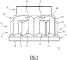
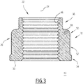
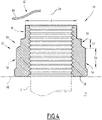
- the figures 1 to 4 represent a nut 10 according to one embodiment of the invention. Said nut is intended to be assembled with a threaded rod 12, visible at figure 4 , to form a fastener 14.
- the nut 10 comprises a body 20 and a bore 22 passing through said body along a main axis 24.
- the body 20 of the nut comprises: a bearing face 30; a driving surface 32; a base 34; a braking skirt 36; and a through hole 38.
- the bearing surface 30 is intended to rest on a surface of a structure 40 ( figure 4 ) assembled to the binding 14.
- the bearing face 30 is substantially flat and perpendicular to the main axis 24.
- the drive surface 32 extends around the main axis 24 and is intended for the screwing/unscrewing of the nut by means of a tool.
- the training surface 32 will be described in more detail below.
- the base 34 is arranged between the drive surface 32 and the bearing face 30.
- the base has a substantially frustoconical shape which flares out from the drive surface 32.
- the braking skirt 36 extends the drive surface 32 with respect to the main axis 24, opposite the base 34 or the bearing surface 30.
- An outer diameter 44 of the braking skirt 36 is less than or equal, preferably substantially equal, to a minimum radial dimension of the drive surface 32.
- the braking skirt has a slightly elliptical shape.
- Through-hole 38 extends substantially perpendicular to major axis 24 from drive surface 32. Through-hole 38 will be described in more detail below.
- the bore 22 is defined by an internal wall 46 of the body 20.
- Said internal wall is substantially cylindrical of revolution and provided with an internal thread, capable of cooperating with the thread of the rod 12.
- the drive surface 32 comprises an upper zone 50 and a lower zone 52, adjacent along the main axis 24.
- the lower zone 52 is located between the upper zone 50 and the base 34, or the support face 30 if the base is omitted.
- a perimeter 54 of the lower zone 52 around the main axis 24 is greater than a perimeter 56 of the upper zone 50.
- the perimeter 54, 56 is considered on a section of the nut 10 perpendicular to the main axis 24.
- the upper zone 50 and the lower zone 52 respectively have a height 57 and a height 58 along the main axis 24.
- the through hole 38 is located in the upper zone 50.
- the height 57 of the upper zone 50 is chosen in particular to allow said through hole to be arranged.
- the drive surface 32 comprises a series of first flats or flats 60 and a series of second flats or flats 62.
- the first 60 and second 62 flats are parallel to the main axis 24.
- the drive surface 32 comprises six first flats 60 of identical dimensions, angularly distributed in a regular manner around the main axis 24.
- the drive surface 32 also comprises six first edges 64, separating two by two the first flats 60.
- the first two flats 60 on either side of a first edge 64 define a convex surface.
- the first flats 60 and the first ridges 64 extend over both the upper zone 50 and the lower zone 52 of the drive surface 32.
- the drive surface has twelve second flats 62 of identical dimensions.
- the second flats 62 form six pairs 66 distributed angularly in a regular manner around the main axis 24. More precisely, each pair 66 of second flats 62 is arranged substantially in the middle of a first flat 60, at equal distance from the first edges 64 delimiting said first flat. Each pair 66 of second flats 62 forms a radial projection relative to the corresponding first flat 60.
- the second flats 62 extend only over the lower area 52 of the drive surface 32 and have a height less than the height of the first flats.
- the drive surface 32 further comprises six second edges 70.
- Each second edge 70 separates two second flats 62 of the same pair 66, defining a convex surface.
- the first 64 and second 70 edges are tangent to the same envelope cylinder 72 with a circular base, centered on the main axis 24.
- the drive surface 32 further comprises twelve third ridges 74.
- Each third ridge 74 separates a first 60 and a second 62 adjacent flats, defining a concave surface.
- the second 70 and third 74 ridges extend only in the lower zone 52 of the driving surface 32.
- the upper zone 50 of the drive surface 32 is a hexagonal surface, while the lower zone 52 of said drive surface is a bi-hexagonal surface.
- the through hole 38 extends between two adjacent first flats 60 . More specifically, the through hole 38 extends between two ends 76, each end opening onto one of said first adjacent flats 60.
- the through hole 38 is arranged away from the bore 22 and does not open onto said bore.
- the through hole 38 is substantially straight between the two ends 76 and extends in a plane perpendicular to the main axis 24.
- the height 57 of the upper zone 50 is chosen to allow the arrangement of the through hole 38.
- height 57 is 2.2mm.
- Such a height 57 allows the drilling of an orifice 38 with a diameter of 1.2 mm, and a height 58 of 5.4 mm for the lower zone 52.
- Such a nut makes it possible to pass a torque of 320 N.m.
- the body 20 comprises several through-holes 38 that are substantially identical and distributed angularly around the main axis 24.
- the body 20 has three through-holes 38 that are identical, substantially arranged at the vertices of an centered on the main axis 24.
- the threaded rod 12 is inserted into a bore of the structure 40 and the nut 10 is screwed onto one end of said rod, by means of a suitable tool (not shown) cooperating with the drive surface 32.
- the surface of the lower zone 52 corresponds to a greater contact surface with the tool, so as to transmit a high tightening torque.
- the bi-hexagonal surface of the lower zone 52 cooperates with a tool (not shown) of complementary shape to said surface.
- the tool also cooperates with the first flats 60 at the level of the upper zone 50, close to the first edges 64, which contributes to increasing the tightening torque.
- the wire brake is for example produced as follows: a first end 80 of a metal wire 82 ( figure 4 ) is introduced into the or one of the through holes 38.
- the metal wire 82 can be wound around a point of attachment to the surface of the structure 40, such as another fixing 14 (not shown).
- a second end of the wire 82 can then be twisted to the first end 80 or attached to another hanging point.
- the nut 10 is thus locked in rotation by the metal wire 82 with respect to the surface of the structure 40.
- the nut 10 offers an optimized tightening torque, efficient braking allowing several assembly/disassembly cycles, while minimizing the height of the nut and allowing the arrangement of an orifice 38 for the brake wire 82 on the drive surface 32 of said nut.
Landscapes
- Engineering & Computer Science (AREA)
- General Engineering & Computer Science (AREA)
- Mechanical Engineering (AREA)
- Transmission Devices (AREA)
- Connection Of Plates (AREA)
- Braking Arrangements (AREA)
Applications Claiming Priority (1)
| Application Number | Priority Date | Filing Date | Title |
|---|---|---|---|
| FR2011880A FR3116312B1 (fr) | 2020-11-19 | 2020-11-19 | Ecrou de freinage et fixation associée |
Publications (2)
| Publication Number | Publication Date |
|---|---|
| EP4001676A1 true EP4001676A1 (de) | 2022-05-25 |
| EP4001676B1 EP4001676B1 (de) | 2023-08-30 |
Family
ID=74045934
Family Applications (1)
| Application Number | Title | Priority Date | Filing Date |
|---|---|---|---|
| EP21208739.9A Active EP4001676B1 (de) | 2020-11-19 | 2021-11-17 | Bremsmutter und entsprechende befestigung |
Country Status (4)
| Country | Link |
|---|---|
| US (1) | US12066049B2 (de) |
| EP (1) | EP4001676B1 (de) |
| CN (1) | CN114542575A (de) |
| FR (1) | FR3116312B1 (de) |
Citations (8)
| Publication number | Priority date | Publication date | Assignee | Title |
|---|---|---|---|---|
| US2686546A (en) | 1947-06-19 | 1954-08-17 | Mac Lean Fogg Lock Nut Co | Self-locking nut and process of manufacturing same |
| US2754871A (en) | 1952-09-04 | 1956-07-17 | Stoll Albert | Self-locking nut having a radially deformed thread portion and method for the production of the same |
| FR1183581A (fr) | 1956-10-23 | 1959-07-09 | Nat Machine Products Company | Perfectionnements aux écrous indesserrables |
| US3275054A (en) * | 1964-12-15 | 1966-09-27 | Standard Pressed Steel Co | Compression locking nut |
| CH425354A (fr) * | 1963-01-11 | 1966-11-30 | Firth Cleveland Fastenings Ltd | Ecrou indesserrable, procédé pour sa fabrication et appareil pour la mise en oeuvre de ce procédé |
| US3674075A (en) * | 1969-11-14 | 1972-07-04 | Shur Lok Corp | Tamper-proof two-way locking nut |
| WO2010085030A1 (ko) * | 2009-01-20 | 2010-07-29 | 주식회사 호크마이엔지 | 너트와 풀림 방지 핀 및 이를 이용한 u볼트 어셈블리 |
| US20180135686A1 (en) * | 2016-11-17 | 2018-05-17 | Goodrich Corporation | Nut retention system |
Family Cites Families (15)
| Publication number | Priority date | Publication date | Assignee | Title |
|---|---|---|---|---|
| US471608A (en) * | 1892-03-29 | Nut-lock | ||
| US177380A (en) * | 1876-05-16 | Improvement in nut-locks | ||
| US653308A (en) * | 1899-10-19 | 1900-07-10 | Edwin Morse | Nut-lock. |
| US2890734A (en) * | 1956-08-02 | 1959-06-16 | John F Mullin | Wire locked bolt assemblies |
| US3140636A (en) * | 1962-09-20 | 1964-07-14 | Kaynar Mfg Co | Twelve-point nut |
| US4092080A (en) * | 1976-06-03 | 1978-05-30 | Pneumo Corporation | Anti-rotation lock for threaded connection |
| US4189976A (en) * | 1978-06-29 | 1980-02-26 | Fargo Manufacturing Company, Inc. | Dual head fastener |
| GB8722021D0 (en) * | 1987-09-18 | 1987-10-28 | British Aerospace | Lock nut assemblies |
| US5842263A (en) * | 1996-01-11 | 1998-12-01 | Westinghouse Electric Corporation | Method and manufacture of an axial tensioned bolt |
| US6150656A (en) * | 1998-12-10 | 2000-11-21 | United Technologies Corporation | Method of assembly and inspection for a gas turbine engine |
| CN202926839U (zh) * | 2012-11-30 | 2013-05-08 | 浙江荣得利航空部件有限公司 | 带槽圆螺母 |
| FR3005332B1 (fr) * | 2013-05-02 | 2015-06-05 | Lisi Aerospace | Boulon de fixation a blocage positif |
| ITUA20164439A1 (it) * | 2016-06-16 | 2017-12-16 | Bimecc Eng S P A | Organo di collegamento, in particolare una vite o un dado, preferibilmente per fissare una ruota, o cerchio, ad un mozzo di un veicolo. |
| CN205895855U (zh) * | 2016-08-19 | 2017-01-18 | 嵇为明 | 防松螺母 |
| CN209016594U (zh) * | 2018-11-29 | 2019-06-21 | 威海市泓淋电力技术股份有限公司 | 一种不沾灰尘的辐照橡胶电缆件 |
-
2020
- 2020-11-19 FR FR2011880A patent/FR3116312B1/fr active Active
-
2021
- 2021-11-05 US US17/520,605 patent/US12066049B2/en active Active
- 2021-11-17 EP EP21208739.9A patent/EP4001676B1/de active Active
- 2021-11-18 CN CN202111370367.9A patent/CN114542575A/zh active Pending
Patent Citations (8)
| Publication number | Priority date | Publication date | Assignee | Title |
|---|---|---|---|---|
| US2686546A (en) | 1947-06-19 | 1954-08-17 | Mac Lean Fogg Lock Nut Co | Self-locking nut and process of manufacturing same |
| US2754871A (en) | 1952-09-04 | 1956-07-17 | Stoll Albert | Self-locking nut having a radially deformed thread portion and method for the production of the same |
| FR1183581A (fr) | 1956-10-23 | 1959-07-09 | Nat Machine Products Company | Perfectionnements aux écrous indesserrables |
| CH425354A (fr) * | 1963-01-11 | 1966-11-30 | Firth Cleveland Fastenings Ltd | Ecrou indesserrable, procédé pour sa fabrication et appareil pour la mise en oeuvre de ce procédé |
| US3275054A (en) * | 1964-12-15 | 1966-09-27 | Standard Pressed Steel Co | Compression locking nut |
| US3674075A (en) * | 1969-11-14 | 1972-07-04 | Shur Lok Corp | Tamper-proof two-way locking nut |
| WO2010085030A1 (ko) * | 2009-01-20 | 2010-07-29 | 주식회사 호크마이엔지 | 너트와 풀림 방지 핀 및 이를 이용한 u볼트 어셈블리 |
| US20180135686A1 (en) * | 2016-11-17 | 2018-05-17 | Goodrich Corporation | Nut retention system |
Also Published As
| Publication number | Publication date |
|---|---|
| FR3116312B1 (fr) | 2022-11-18 |
| EP4001676B1 (de) | 2023-08-30 |
| US20220154759A1 (en) | 2022-05-19 |
| US12066049B2 (en) | 2024-08-20 |
| FR3116312A1 (fr) | 2022-05-20 |
| CN114542575A (zh) | 2022-05-27 |
Similar Documents
| Publication | Publication Date | Title |
|---|---|---|
| EP3325827B1 (de) | Anordnung mit verriegeltem sicherungsbolzen | |
| EP3200957B1 (de) | Demontierextraktionssystem für eine turbomaschine | |
| EP0156681B1 (de) | Bolzenschraubgerät | |
| EP3695129B1 (de) | Nutmutter für blindbefestigung, niete und anordnung mit einer solchen mutter | |
| FR2987881A1 (fr) | Dispositif de raccordement securise, notamment pour canalisation, embout pour ce dispositif et procede de fabrication d'un ecrou associe. | |
| EP1162376A1 (de) | Befestigungsvorrichtung mit einer Vertiefung am Ende ihres Gewindestabes | |
| EP1825151B1 (de) | Metallplatte, verfahren zur befestigung der metallplatte durch fliessbohren und diese umfassende anordnung | |
| FR2636734A1 (fr) | Dispositif pour fixer un compteur d'eau sur une embase et procede s'y rapportant | |
| CH619518A5 (de) | ||
| EP0402198A1 (de) | Verriegelungsmutter | |
| CA3066174A1 (fr) | Fixation a verrouillage positif | |
| EP3298286B1 (de) | Verbessertes befestigungselement | |
| FR2959284A1 (fr) | Dispositif de fixation rapide par insertion avec possibilite d'ajustement | |
| EP4001676B1 (de) | Bremsmutter und entsprechende befestigung | |
| FR2895467A1 (fr) | Agencement pour l'assemblage de deux pieces par vissage par l'intermediaire d'un ensemble vis-ecrou | |
| EP1231422B1 (de) | Verfahren zur Herstellung einer unverlierbaren Schraube, Fixierungstellringe für Rohrleitungen und Gebrauch von dem Prozess, die Stellringe herzustellen | |
| EP4242479B1 (de) | Längenverstellbare koppelstange mit einem verdrehsicherungssystem, das mit einem verbindungssystem der koppelstange zusammenarbeitet, luftfahrzeug, das mindestens eine solche koppelstange umfasst | |
| EP2094978B1 (de) | Mutter mit verformbarem bund | |
| FR2897124A1 (fr) | Dispositif d'immobilisation en rotation d'un ecrou a sertir | |
| FR2751383A1 (fr) | Ecrou noye a sertir en aveugle et a tete fine encastree | |
| EP3859170B1 (de) | Bolzen, der eine mutter und mindestens eine unterlegscheibe umfasst, die durch härtung eines pastösen materials erhalten wurde, verfahren zur montage dieses bolzens und baugruppe mit mindestens einem solchen bolzen | |
| EP0271625B1 (de) | Nichtlösbare Mutter | |
| WO2000031846A1 (fr) | Presse-etoupe a garniture d'etancheite et dents de serrage epaisses | |
| FR2811699A1 (fr) | Charniere a couple controle | |
| FR2991410A1 (fr) | Ensemble de serrage a vis |
Legal Events
| Date | Code | Title | Description |
|---|---|---|---|
| PUAI | Public reference made under article 153(3) epc to a published international application that has entered the european phase |
Free format text: ORIGINAL CODE: 0009012 |
|
| STAA | Information on the status of an ep patent application or granted ep patent |
Free format text: STATUS: THE APPLICATION HAS BEEN PUBLISHED |
|
| AK | Designated contracting states |
Kind code of ref document: A1 Designated state(s): AL AT BE BG CH CY CZ DE DK EE ES FI FR GB GR HR HU IE IS IT LI LT LU LV MC MK MT NL NO PL PT RO RS SE SI SK SM TR |
|
| STAA | Information on the status of an ep patent application or granted ep patent |
Free format text: STATUS: REQUEST FOR EXAMINATION WAS MADE |
|
| 17P | Request for examination filed |
Effective date: 20221114 |
|
| RBV | Designated contracting states (corrected) |
Designated state(s): AL AT BE BG CH CY CZ DE DK EE ES FI FR GB GR HR HU IE IS IT LI LT LU LV MC MK MT NL NO PL PT RO RS SE SI SK SM TR |
|
| GRAP | Despatch of communication of intention to grant a patent |
Free format text: ORIGINAL CODE: EPIDOSNIGR1 |
|
| STAA | Information on the status of an ep patent application or granted ep patent |
Free format text: STATUS: GRANT OF PATENT IS INTENDED |
|
| RIC1 | Information provided on ipc code assigned before grant |
Ipc: F16B 39/284 20060101ALI20230310BHEP Ipc: F16B 39/10 20060101AFI20230310BHEP |
|
| INTG | Intention to grant announced |
Effective date: 20230406 |
|
| GRAS | Grant fee paid |
Free format text: ORIGINAL CODE: EPIDOSNIGR3 |
|
| GRAA | (expected) grant |
Free format text: ORIGINAL CODE: 0009210 |
|
| STAA | Information on the status of an ep patent application or granted ep patent |
Free format text: STATUS: THE PATENT HAS BEEN GRANTED |
|
| AK | Designated contracting states |
Kind code of ref document: B1 Designated state(s): AL AT BE BG CH CY CZ DE DK EE ES FI FR GB GR HR HU IE IS IT LI LT LU LV MC MK MT NL NO PL PT RO RS SE SI SK SM TR |
|
| REG | Reference to a national code |
Ref country code: GB Ref legal event code: FG4D Free format text: NOT ENGLISH |
|
| REG | Reference to a national code |
Ref country code: CH Ref legal event code: EP |
|
| REG | Reference to a national code |
Ref country code: DE Ref legal event code: R096 Ref document number: 602021004709 Country of ref document: DE |
|
| REG | Reference to a national code |
Ref country code: IE Ref legal event code: FG4D Free format text: LANGUAGE OF EP DOCUMENT: FRENCH |
|
| REG | Reference to a national code |
Ref country code: LT Ref legal event code: MG9D |
|
| REG | Reference to a national code |
Ref country code: NL Ref legal event code: MP Effective date: 20230830 |
|
| REG | Reference to a national code |
Ref country code: AT Ref legal event code: MK05 Ref document number: 1605789 Country of ref document: AT Kind code of ref document: T Effective date: 20230830 |
|
| PG25 | Lapsed in a contracting state [announced via postgrant information from national office to epo] |
Ref country code: GR Free format text: LAPSE BECAUSE OF FAILURE TO SUBMIT A TRANSLATION OF THE DESCRIPTION OR TO PAY THE FEE WITHIN THE PRESCRIBED TIME-LIMIT Effective date: 20231201 |
|
| PG25 | Lapsed in a contracting state [announced via postgrant information from national office to epo] |
Ref country code: IS Free format text: LAPSE BECAUSE OF FAILURE TO SUBMIT A TRANSLATION OF THE DESCRIPTION OR TO PAY THE FEE WITHIN THE PRESCRIBED TIME-LIMIT Effective date: 20231230 |
|
| PG25 | Lapsed in a contracting state [announced via postgrant information from national office to epo] |
Ref country code: SE Free format text: LAPSE BECAUSE OF FAILURE TO SUBMIT A TRANSLATION OF THE DESCRIPTION OR TO PAY THE FEE WITHIN THE PRESCRIBED TIME-LIMIT Effective date: 20230830 Ref country code: RS Free format text: LAPSE BECAUSE OF FAILURE TO SUBMIT A TRANSLATION OF THE DESCRIPTION OR TO PAY THE FEE WITHIN THE PRESCRIBED TIME-LIMIT Effective date: 20230830 Ref country code: NO Free format text: LAPSE BECAUSE OF FAILURE TO SUBMIT A TRANSLATION OF THE DESCRIPTION OR TO PAY THE FEE WITHIN THE PRESCRIBED TIME-LIMIT Effective date: 20231130 Ref country code: LV Free format text: LAPSE BECAUSE OF FAILURE TO SUBMIT A TRANSLATION OF THE DESCRIPTION OR TO PAY THE FEE WITHIN THE PRESCRIBED TIME-LIMIT Effective date: 20230830 Ref country code: LT Free format text: LAPSE BECAUSE OF FAILURE TO SUBMIT A TRANSLATION OF THE DESCRIPTION OR TO PAY THE FEE WITHIN THE PRESCRIBED TIME-LIMIT Effective date: 20230830 Ref country code: IS Free format text: LAPSE BECAUSE OF FAILURE TO SUBMIT A TRANSLATION OF THE DESCRIPTION OR TO PAY THE FEE WITHIN THE PRESCRIBED TIME-LIMIT Effective date: 20231230 Ref country code: HR Free format text: LAPSE BECAUSE OF FAILURE TO SUBMIT A TRANSLATION OF THE DESCRIPTION OR TO PAY THE FEE WITHIN THE PRESCRIBED TIME-LIMIT Effective date: 20230830 Ref country code: GR Free format text: LAPSE BECAUSE OF FAILURE TO SUBMIT A TRANSLATION OF THE DESCRIPTION OR TO PAY THE FEE WITHIN THE PRESCRIBED TIME-LIMIT Effective date: 20231201 Ref country code: FI Free format text: LAPSE BECAUSE OF FAILURE TO SUBMIT A TRANSLATION OF THE DESCRIPTION OR TO PAY THE FEE WITHIN THE PRESCRIBED TIME-LIMIT Effective date: 20230830 Ref country code: AT Free format text: LAPSE BECAUSE OF FAILURE TO SUBMIT A TRANSLATION OF THE DESCRIPTION OR TO PAY THE FEE WITHIN THE PRESCRIBED TIME-LIMIT Effective date: 20230830 |
|
| PG25 | Lapsed in a contracting state [announced via postgrant information from national office to epo] |
Ref country code: PL Free format text: LAPSE BECAUSE OF FAILURE TO SUBMIT A TRANSLATION OF THE DESCRIPTION OR TO PAY THE FEE WITHIN THE PRESCRIBED TIME-LIMIT Effective date: 20230830 Ref country code: NL Free format text: LAPSE BECAUSE OF FAILURE TO SUBMIT A TRANSLATION OF THE DESCRIPTION OR TO PAY THE FEE WITHIN THE PRESCRIBED TIME-LIMIT Effective date: 20230830 |
|
| PG25 | Lapsed in a contracting state [announced via postgrant information from national office to epo] |
Ref country code: ES Free format text: LAPSE BECAUSE OF FAILURE TO SUBMIT A TRANSLATION OF THE DESCRIPTION OR TO PAY THE FEE WITHIN THE PRESCRIBED TIME-LIMIT Effective date: 20230830 |
|
| PG25 | Lapsed in a contracting state [announced via postgrant information from national office to epo] |
Ref country code: SM Free format text: LAPSE BECAUSE OF FAILURE TO SUBMIT A TRANSLATION OF THE DESCRIPTION OR TO PAY THE FEE WITHIN THE PRESCRIBED TIME-LIMIT Effective date: 20230830 Ref country code: RO Free format text: LAPSE BECAUSE OF FAILURE TO SUBMIT A TRANSLATION OF THE DESCRIPTION OR TO PAY THE FEE WITHIN THE PRESCRIBED TIME-LIMIT Effective date: 20230830 Ref country code: ES Free format text: LAPSE BECAUSE OF FAILURE TO SUBMIT A TRANSLATION OF THE DESCRIPTION OR TO PAY THE FEE WITHIN THE PRESCRIBED TIME-LIMIT Effective date: 20230830 Ref country code: EE Free format text: LAPSE BECAUSE OF FAILURE TO SUBMIT A TRANSLATION OF THE DESCRIPTION OR TO PAY THE FEE WITHIN THE PRESCRIBED TIME-LIMIT Effective date: 20230830 Ref country code: DK Free format text: LAPSE BECAUSE OF FAILURE TO SUBMIT A TRANSLATION OF THE DESCRIPTION OR TO PAY THE FEE WITHIN THE PRESCRIBED TIME-LIMIT Effective date: 20230830 Ref country code: CZ Free format text: LAPSE BECAUSE OF FAILURE TO SUBMIT A TRANSLATION OF THE DESCRIPTION OR TO PAY THE FEE WITHIN THE PRESCRIBED TIME-LIMIT Effective date: 20230830 Ref country code: SK Free format text: LAPSE BECAUSE OF FAILURE TO SUBMIT A TRANSLATION OF THE DESCRIPTION OR TO PAY THE FEE WITHIN THE PRESCRIBED TIME-LIMIT Effective date: 20230830 Ref country code: PT Free format text: LAPSE BECAUSE OF FAILURE TO SUBMIT A TRANSLATION OF THE DESCRIPTION OR TO PAY THE FEE WITHIN THE PRESCRIBED TIME-LIMIT Effective date: 20240102 |
|
| PG25 | Lapsed in a contracting state [announced via postgrant information from national office to epo] |
Ref country code: IT Free format text: LAPSE BECAUSE OF FAILURE TO SUBMIT A TRANSLATION OF THE DESCRIPTION OR TO PAY THE FEE WITHIN THE PRESCRIBED TIME-LIMIT Effective date: 20230830 |
|
| REG | Reference to a national code |
Ref country code: DE Ref legal event code: R097 Ref document number: 602021004709 Country of ref document: DE |
|
| PG25 | Lapsed in a contracting state [announced via postgrant information from national office to epo] |
Ref country code: MC Free format text: LAPSE BECAUSE OF FAILURE TO SUBMIT A TRANSLATION OF THE DESCRIPTION OR TO PAY THE FEE WITHIN THE PRESCRIBED TIME-LIMIT Effective date: 20230830 |
|
| PLBE | No opposition filed within time limit |
Free format text: ORIGINAL CODE: 0009261 |
|
| STAA | Information on the status of an ep patent application or granted ep patent |
Free format text: STATUS: NO OPPOSITION FILED WITHIN TIME LIMIT |
|
| PG25 | Lapsed in a contracting state [announced via postgrant information from national office to epo] |
Ref country code: LU Free format text: LAPSE BECAUSE OF NON-PAYMENT OF DUE FEES Effective date: 20231117 |
|
| PG25 | Lapsed in a contracting state [announced via postgrant information from national office to epo] |
Ref country code: MC Free format text: LAPSE BECAUSE OF FAILURE TO SUBMIT A TRANSLATION OF THE DESCRIPTION OR TO PAY THE FEE WITHIN THE PRESCRIBED TIME-LIMIT Effective date: 20230830 Ref country code: LU Free format text: LAPSE BECAUSE OF NON-PAYMENT OF DUE FEES Effective date: 20231117 Ref country code: SI Free format text: LAPSE BECAUSE OF FAILURE TO SUBMIT A TRANSLATION OF THE DESCRIPTION OR TO PAY THE FEE WITHIN THE PRESCRIBED TIME-LIMIT Effective date: 20230830 |
|
| REG | Reference to a national code |
Ref country code: BE Ref legal event code: MM Effective date: 20231130 |
|
| 26N | No opposition filed |
Effective date: 20240603 |
|
| REG | Reference to a national code |
Ref country code: IE Ref legal event code: MM4A |
|
| PG25 | Lapsed in a contracting state [announced via postgrant information from national office to epo] |
Ref country code: IE Free format text: LAPSE BECAUSE OF NON-PAYMENT OF DUE FEES Effective date: 20231117 |
|
| PG25 | Lapsed in a contracting state [announced via postgrant information from national office to epo] |
Ref country code: BE Free format text: LAPSE BECAUSE OF NON-PAYMENT OF DUE FEES Effective date: 20231130 |
|
| PG25 | Lapsed in a contracting state [announced via postgrant information from national office to epo] |
Ref country code: IE Free format text: LAPSE BECAUSE OF NON-PAYMENT OF DUE FEES Effective date: 20231117 Ref country code: BE Free format text: LAPSE BECAUSE OF NON-PAYMENT OF DUE FEES Effective date: 20231130 |
|
| PG25 | Lapsed in a contracting state [announced via postgrant information from national office to epo] |
Ref country code: BG Free format text: LAPSE BECAUSE OF FAILURE TO SUBMIT A TRANSLATION OF THE DESCRIPTION OR TO PAY THE FEE WITHIN THE PRESCRIBED TIME-LIMIT Effective date: 20230830 |
|
| PG25 | Lapsed in a contracting state [announced via postgrant information from national office to epo] |
Ref country code: BG Free format text: LAPSE BECAUSE OF FAILURE TO SUBMIT A TRANSLATION OF THE DESCRIPTION OR TO PAY THE FEE WITHIN THE PRESCRIBED TIME-LIMIT Effective date: 20230830 |
|
| REG | Reference to a national code |
Ref country code: CH Ref legal event code: PL |
|
| REG | Reference to a national code |
Ref country code: CH Ref legal event code: PL |
|
| PG25 | Lapsed in a contracting state [announced via postgrant information from national office to epo] |
Ref country code: CH Free format text: LAPSE BECAUSE OF NON-PAYMENT OF DUE FEES Effective date: 20241130 |
|
| PG25 | Lapsed in a contracting state [announced via postgrant information from national office to epo] |
Ref country code: CY Free format text: LAPSE BECAUSE OF FAILURE TO SUBMIT A TRANSLATION OF THE DESCRIPTION OR TO PAY THE FEE WITHIN THE PRESCRIBED TIME-LIMIT; INVALID AB INITIO Effective date: 20211117 |
|
| PG25 | Lapsed in a contracting state [announced via postgrant information from national office to epo] |
Ref country code: TR Free format text: LAPSE BECAUSE OF FAILURE TO SUBMIT A TRANSLATION OF THE DESCRIPTION OR TO PAY THE FEE WITHIN THE PRESCRIBED TIME-LIMIT Effective date: 20230830 |
|
| PGFP | Annual fee paid to national office [announced via postgrant information from national office to epo] |
Ref country code: DE Payment date: 20251117 Year of fee payment: 5 |
|
| PGFP | Annual fee paid to national office [announced via postgrant information from national office to epo] |
Ref country code: GB Payment date: 20251126 Year of fee payment: 5 |
|
| PGFP | Annual fee paid to national office [announced via postgrant information from national office to epo] |
Ref country code: FR Payment date: 20251127 Year of fee payment: 5 |
|
| PG25 | Lapsed in a contracting state [announced via postgrant information from national office to epo] |
Ref country code: HU Free format text: LAPSE BECAUSE OF FAILURE TO SUBMIT A TRANSLATION OF THE DESCRIPTION OR TO PAY THE FEE WITHIN THE PRESCRIBED TIME-LIMIT; INVALID AB INITIO Effective date: 20211117 |