EP4001691B1 - Stossdämpfer - Google Patents
Stossdämpfer Download PDFInfo
- Publication number
- EP4001691B1 EP4001691B1 EP19937543.7A EP19937543A EP4001691B1 EP 4001691 B1 EP4001691 B1 EP 4001691B1 EP 19937543 A EP19937543 A EP 19937543A EP 4001691 B1 EP4001691 B1 EP 4001691B1
- Authority
- EP
- European Patent Office
- Prior art keywords
- cylinder
- sensor
- shock absorber
- recessed
- coupling member
- Prior art date
- Legal status (The legal status is an assumption and is not a legal conclusion. Google has not performed a legal analysis and makes no representation as to the accuracy of the status listed.)
- Active
Links
Images




Classifications
-
- B—PERFORMING OPERATIONS; TRANSPORTING
- B60—VEHICLES IN GENERAL
- B60G—VEHICLE SUSPENSION ARRANGEMENTS
- B60G11/00—Resilient suspensions characterised by arrangement, location or kind of springs
- B60G11/14—Resilient suspensions characterised by arrangement, location or kind of springs having helical, spiral or coil springs only
- B60G11/16—Resilient suspensions characterised by arrangement, location or kind of springs having helical, spiral or coil springs only characterised by means specially adapted for attaching the spring to axle or sprung part of the vehicle
-
- B—PERFORMING OPERATIONS; TRANSPORTING
- B60—VEHICLES IN GENERAL
- B60G—VEHICLE SUSPENSION ARRANGEMENTS
- B60G17/00—Resilient suspensions having means for adjusting the spring or vibration-damper characteristics, for regulating the distance between a supporting surface and a sprung part of vehicle or for locking suspension during use to meet varying vehicular or surface conditions, e.g. due to speed or load
- B60G17/015—Resilient suspensions having means for adjusting the spring or vibration-damper characteristics, for regulating the distance between a supporting surface and a sprung part of vehicle or for locking suspension during use to meet varying vehicular or surface conditions, e.g. due to speed or load the regulating means comprising electric or electronic elements
- B60G17/019—Resilient suspensions having means for adjusting the spring or vibration-damper characteristics, for regulating the distance between a supporting surface and a sprung part of vehicle or for locking suspension during use to meet varying vehicular or surface conditions, e.g. due to speed or load the regulating means comprising electric or electronic elements characterised by the type of sensor or the arrangement thereof
-
- B—PERFORMING OPERATIONS; TRANSPORTING
- B60—VEHICLES IN GENERAL
- B60G—VEHICLE SUSPENSION ARRANGEMENTS
- B60G17/00—Resilient suspensions having means for adjusting the spring or vibration-damper characteristics, for regulating the distance between a supporting surface and a sprung part of vehicle or for locking suspension during use to meet varying vehicular or surface conditions, e.g. due to speed or load
- B60G17/02—Spring characteristics, e.g. mechanical springs and mechanical adjusting means
-
- B—PERFORMING OPERATIONS; TRANSPORTING
- B62—LAND VEHICLES FOR TRAVELLING OTHERWISE THAN ON RAILS
- B62K—CYCLES; CYCLE FRAMES; CYCLE STEERING DEVICES; RIDER-OPERATED TERMINAL CONTROLS SPECIALLY ADAPTED FOR CYCLES; CYCLE AXLE SUSPENSIONS; CYCLE SIDECARS, FORECARS, OR THE LIKE
- B62K25/00—Axle suspensions
- B62K25/04—Axle suspensions for mounting axles resiliently on cycle frame or fork
- B62K25/06—Axle suspensions for mounting axles resiliently on cycle frame or fork with telescopic fork, e.g. including auxiliary rocking arms
- B62K25/10—Axle suspensions for mounting axles resiliently on cycle frame or fork with telescopic fork, e.g. including auxiliary rocking arms for rear wheel
-
- F—MECHANICAL ENGINEERING; LIGHTING; HEATING; WEAPONS; BLASTING
- F16—ENGINEERING ELEMENTS AND UNITS; GENERAL MEASURES FOR PRODUCING AND MAINTAINING EFFECTIVE FUNCTIONING OF MACHINES OR INSTALLATIONS; THERMAL INSULATION IN GENERAL
- F16F—SPRINGS; SHOCK-ABSORBERS; MEANS FOR DAMPING VIBRATION
- F16F9/00—Springs, vibration-dampers, shock-absorbers, or similarly-constructed movement-dampers using a fluid or the equivalent as damping medium
- F16F9/32—Details
- F16F9/3292—Sensor arrangements
-
- F—MECHANICAL ENGINEERING; LIGHTING; HEATING; WEAPONS; BLASTING
- F16—ENGINEERING ELEMENTS AND UNITS; GENERAL MEASURES FOR PRODUCING AND MAINTAINING EFFECTIVE FUNCTIONING OF MACHINES OR INSTALLATIONS; THERMAL INSULATION IN GENERAL
- F16F—SPRINGS; SHOCK-ABSORBERS; MEANS FOR DAMPING VIBRATION
- F16F9/00—Springs, vibration-dampers, shock-absorbers, or similarly-constructed movement-dampers using a fluid or the equivalent as damping medium
- F16F9/32—Details
- F16F9/44—Means on or in the damper for manual or non-automatic adjustment; such means combined with temperature correction
- F16F9/46—Means on or in the damper for manual or non-automatic adjustment; such means combined with temperature correction allowing control from a distance, i.e. location of means for control input being remote from site of valves, e.g. on damper external wall
-
- F—MECHANICAL ENGINEERING; LIGHTING; HEATING; WEAPONS; BLASTING
- F16—ENGINEERING ELEMENTS AND UNITS; GENERAL MEASURES FOR PRODUCING AND MAINTAINING EFFECTIVE FUNCTIONING OF MACHINES OR INSTALLATIONS; THERMAL INSULATION IN GENERAL
- F16F—SPRINGS; SHOCK-ABSORBERS; MEANS FOR DAMPING VIBRATION
- F16F9/00—Springs, vibration-dampers, shock-absorbers, or similarly-constructed movement-dampers using a fluid or the equivalent as damping medium
- F16F9/32—Details
- F16F9/56—Means for adjusting the length of, or for locking, the spring or damper, e.g. at the end of the stroke
-
- G—PHYSICS
- G01—MEASURING; TESTING
- G01D—MEASURING NOT SPECIALLY ADAPTED FOR A SPECIFIC VARIABLE; ARRANGEMENTS FOR MEASURING TWO OR MORE VARIABLES NOT COVERED IN A SINGLE OTHER SUBCLASS; TARIFF METERING APPARATUS; MEASURING OR TESTING NOT OTHERWISE PROVIDED FOR
- G01D11/00—Component parts of measuring arrangements not specially adapted for a specific variable
- G01D11/30—Supports specially adapted for an instrument; Supports specially adapted for a set of instruments
-
- B—PERFORMING OPERATIONS; TRANSPORTING
- B60—VEHICLES IN GENERAL
- B60G—VEHICLE SUSPENSION ARRANGEMENTS
- B60G2204/00—Indexing codes related to suspensions per se or to auxiliary parts
- B60G2204/10—Mounting of suspension elements
- B60G2204/11—Mounting of sensors thereon
- B60G2204/112—Mounting of sensors thereon on dampers, e.g. fluid dampers
-
- B—PERFORMING OPERATIONS; TRANSPORTING
- B60—VEHICLES IN GENERAL
- B60G—VEHICLE SUSPENSION ARRANGEMENTS
- B60G2300/00—Indexing codes relating to the type of vehicle
- B60G2300/12—Cycles; Motorcycles
-
- B—PERFORMING OPERATIONS; TRANSPORTING
- B60—VEHICLES IN GENERAL
- B60G—VEHICLE SUSPENSION ARRANGEMENTS
- B60G2500/00—Indexing codes relating to the regulated action or device
- B60G2500/30—Height or ground clearance
Definitions
- the present invention relates to a shock absorber which generates a damping force when a piston is displaced.
- a shock absorber is generally mounted on a straddle type vehicle such as a two-wheel vehicle.
- a piston is provided in a cylinder, and the piston generates a damping force when the piston is displaced due to unevenness of a road surface or the like.
- Patent Literature 1 discloses a technique serving as a technique in the related art related to such a shock absorber.
- the shock absorber disclosed in Patent Literature 1 is used in a motorcycle or the like, and is provided with a detection unit including a sensor for detecting a displacement of a vehicle height.
- Patent Literature 2 shows a shock absorber that includes a suspension spring configured to bias the shock absorber main body in an extension direction. It is possible to detect a displacement of a spring bearing at one position in a circumferential direction by a stroke sensor.
- the shock absorber since the shock absorber includes the sensor, the displacement of the vehicle height can be detected.
- the shock absorber is a device which repeats expansion and contraction, and a load is applied to the sensor used in the shock absorber.
- An object of the present invention is to provide a shock absorber which can reduce a load which may be applied to the sensor.
- a coupling member is disposed between a receiving member receiving a spring and a sensor, and the receiving member and the sensor are coupled to each other via the coupling member, and (2) the coupling member allows a movement of the sensor along a circumferential direction of the receiving member and allows a movement of the sensor along an axial direction, so that a load which may be applied to the sensor can be reduced.
- the present invention is completed based on this finding.
- a shock absorber including:
- the receiving member may include a first flange portion which is the protruding portion formed into an annular shape around the axis,
- the receiving member may include a second recessed portion over a circumferential direction, the second recessed portion being the recessed portion formed into a recessed shape toward a center on an outer circumferential edge of the receiving member,
- the sensor may be disposed outside the cylinder.
- the core portion may have a circular cross-sectional shape whose normal direction is an axial direction of the core portion.
- the sensor may include a guide portion configured to guide a movement of the core portion along the axial direction of the core portion, and the core portion may be disposed between the guide portion and the cylinder.
- the guide portion may be disposed at a distance apart from the cylinder, and the distance may be smaller than a width of the core portion in a radial direction of the cylinder.
- a shock absorber including:
- a shock absorber including:
- left and right refer to left and right with respect to an occupant of a vehicle
- front and rear refer to front and rear with respect to a traveling direction of the vehicle.
- Up indicates an upper direction
- Dn indicates a lower direction.
- the embodiments illustrated in the accompanying drawings are examples of the present invention, and the present invention is not limited to the embodiments.
- a shock absorber according to the present invention can be used as a front fork 13 or a rear cushion 20.
- the description will be made based on an example applied to the rear cushion 20 of a two-wheel vehicle 10 (an example in which the shock absorber according to the present invention is used as the rear cushion 20.
- the rear cushion 20 may be referred to as a "shock absorber 20").
- the two-wheel vehicle 10 (straddle type vehicle 10) includes a vehicle body 11, an engine 12 serving as a power source supported at a lower center portion of the vehicle body 11, left and right front forks 13 (only the right front fork 13 is illustrated in the drawing) provided at left and right sides of a front portion of the vehicle body 11 and absorb an impact received due to unevenness of a road surface, a front wheel 14 which is interposed between the front forks 13 and is rotatably supported, handle pipes 15 which are disposed at upper portions of the front forks 13 and steer the front wheel 14, a seat 16 provided above the engine 12 and on which an occupant sits, a swing arm 17 which extends from a rear portion of the vehicle body 11 to a rear side and which is swingable in an upper-lower direction, a rear wheel 18 which is rotatably supported by the swing arm 17, and left and right rear cushions 20 (only the right rear cushion 20 is illustrated in the drawing) which are provided to cross from a rear portion of the vehicle body 11 to the swing arm 17.
- the left and right rear cushions 20 have the same configuration. Hereinafter, the right rear cushion 20 will be described, and the description of the left rear cushion will be omitted.
- the left and right rear cushions 20 may have different configurations depending on purposes.
- An upper end of the shock absorber 20 is fixed to the vehicle body 11 and a lower end of the shock absorber 20 is fixed to the swing arm 17.
- the shock absorber 20 includes a main body portion 30 which is located at an upper portion and is filled with oil, a rod unit 50 which is located at a lower portion and is provided to be able to move forward or backward relative to the main body portion 30, a spring 25 which biases the main body portion 30 and the rod unit 50 so as to separate the main body portion 30 and the rod unit 50 from each other, and an adjustment unit 60 which adjusts a preload by displacing a position of an upper end of the spring 25 in a height direction (an upper-lower direction).
- the main body portion 30 includes a main body portion stay 31 of which an upper portion is connected to the vehicle body 11 (see FIG. 1 ) and a lower portion is formed into a cap shape, a cylindrical cylinder 40 of which an upper end is fastened to the main body portion stay 31, and a spring receiving portion 33 (a receiving member 33) which is provided at an outer side of the cylinder 40 to be able to move upward and downward and receives an upper end of the spring 25.
- the rod unit 50 includes a rod side stay 51 fixed to the swing arm 17 (see FIG. 1 ), a substantially cylindrical piston rod 52 of which a lower end is fitted into the rod side stay 51, a piston 53 which is fixed to a tip end of the piston rod 52 and located inside the cylinder 40, and a spring receiving portion 54 which is fixed to the rod side stay 51 and receives a lower end of the spring 25.
- the spring 25 is implemented by a compression coil spring.
- the adjustment unit 60 includes a jack portion 70 which comes into contact with the spring receiving portion 33 and displaces the spring receiving portion 33 downward by a hydraulic pressure, a pump 80 which is connected to the jack portion 70 and can feed oil, a sensor 90 which can detect a position of the spring receiving portion 33 in an axial direction of the cylinder 40 (for example, a distance between a lower end of a plunger 72 to be described later and the spring receiving portion 33), an operation unit 64 for setting an adjustment amount of a preload, and a control unit 65 which operates the pump 80 based on information from the sensor 90 and the operation unit 64.
- the cylinder 40 includes an upper lid portion 41 to which the main body portion stay 31 is fixed, a cylinder main body 42 which is screwed to an inner circumference of the upper lid portion 41 and of which an upper end is closed, a lower lid portion 43 which closes a lower end of the cylinder main body 42, and an extension portion 44 which is integrally formed with the upper lid portion 41 and extends from the upper lid portion 41 along an outer circumferential surface of the cylinder main body 42.
- the extension portion 44 includes a sensor holding portion 44a which bulges outward in a radial direction of the cylinder and holds the sensor 90. That is, it can be said that the sensor holding portion 44a is integrally formed with the cylinder 40.
- the spring receiving portion 33 can move relative to the outer circumferential surface of the cylinder main body 42 along an axis CL1, and is provided to be rotatable around the axis CL1.
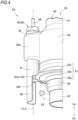
- the spring receiving portion 33 includes a cylindrical base portion 33a disposed along the outer circumferential surface of the cylinder main body 42, a spring receiving main body 33b which is a plate-shaped annular portion protruding from the base portion 33a toward an outer side in the radial direction of the cylinder 40 and which comes into contact with an upper end of the spring 25, a first flange portion 33c (a protruding portion 33c) which is formed adjacent to the spring receiving main body 33b and of which an outer edge is connected to the sensor 90 via a coupling member 100 to be described later, and a claw portion 33d which extends downward from a lower end of the base portion 33a and of which a lower end is formed into a claw shape.
- a contact member 34 which can come into contact with the jack portion 70 is fixed to an outer side of an upper end of the base portion 33a.
- the upper end of the base portion 33a is located above an upper surface of the contact member 34.
- the first flange portion 33c is a plate-shaped member formed into an annular shape in a similar manner to the spring receiving main body 33b.
- a thickness of the first flange portion 33c (a thickness in the axial direction of the cylinder 40. The same applies hereinafter.) is smaller than a thickness of the spring receiving main body 33b. Therefore, the first flange portion 33c is easily bent in the upper-lower direction.
- a seal member 36 is attached to the claw portion 33d.
- the seal member 36 is a member for preventing dust from entering between the spring receiving portion 33 and the cylinder main body 42 (the cylinder 40).
- the piston rod 52 is provided to be movable along the axis CL1 inside the cylinder main body 42. A downward force is applied to the piston rod 52 by the spring 25 so as to separate the piston rod 52 from the cylinder 40. An upper end of the piston rod 52 faces an inner side of the cylinder 40.
- the piston 53 is configured such that oil can pass through an inner side of the piston 53, and the piston 53 is movable in the upper-lower direction in the cylinder main body 42 together with the piston rod 52.
- oil passes through the inner side of the piston 53, and a damping force is generated.
- the jack portion 70 is housed in a space formed between the cylinder main body 42 and the extension portion 44.
- the jack portion 70 includes a jack housing 71 fixed along an inner circumferential surface of the extension portion 44, a plunger 72 which is provided in a manner in which the plunger 72 can be lifted and lowered along an outer circumferential surface of the cylinder main body 42 and of which a lower end comes into contact with an upper surface of the base portion 33a, and a jack chamber 73 which is a region surrounded by the jack housing 71 and the plunger 72 and is filled with oil fed from the pump 80 (see FIG. 2 ).
- the pump 80 is a liquid feed pump for feeding oil to the jack chamber 73.
- the pump 80 includes a motor 81, a pump case 82 filled with oil, and an adjustment unit 83 of which a tip end is positioned at the pump case 82 and which can be lifted and lowered by operating the motor 81.
- the sensor 90 includes a sensor main body 91 which is formed into a substantially cylindrical shape and is held by the sensor holding portion 44a, a fixed lid portion 92 which is fastened to an inner periphery of the sensor holding portion 44a and prevents the sensor main body 91 from coming off, a seal member 93 which is provided inside an upper end of the fixed lid portion 92 and prevents dust from entering the sensor 90, a sensor outer cylinder portion 94 which is positioned below the seal member 93 and is fixed along inner circumferential surfaces of the sensor main body 91 and the fixed lid portion 92, a bottomed cylindrical sensor inner cylinder portion 95 which is provided along an inner circumferential surface of the sensor outer cylinder portion 94, a coil portion 96 which is formed of a conductive wire wound around an outer side of the sensor inner cylinder portion 95, a core portion 97 which is provided to be movable upward and downward inside the sensor inner cylinder portion 95, a guide portion 98 which extends further downward from a lower end of the sensor main body 91 and guides
- the sensor main body 91 can be inserted into the sensor holding portion 44a from above the sensor holding portion 44a.
- the sensor main body 91 is a member in which an outer diameter of an upper end is larger than an outer diameter of other portions.
- the upper end of the sensor main body 91 is supported by a protruding portion which protrudes inward from an inner circumferential surface of the sensor holding portion 44a, thereby preventing the sensor main body 91 from falling downward.
- An axis CL2 of the sensor main body 91 extends parallel to the axis CL1 of the cylinder 40.
- a part of an outer circumferential surface of the fixed lid portion 92 is formed into a male screw shape, and is fastened to an inner circumferential surface of the sensor holding portion 44a formed into a female screw shape.
- the sensor inner cylinder portion 95 is fixed to an inner side of the sensor outer cylinder portion 94. Each of an upper end and a lower end of the sensor inner cylinder portion 95 protrudes outward in a radial direction of the sensor inner cylinder portion 95, and prevents the coil portion 96 from coming off.
- the coil portion 96 is accommodated in a space formed between the sensor outer cylinder portion 94 and the sensor inner cylinder portion 95.
- the coil portion 96 can be energized.
- the core portion 97 is formed into a substantially columnar shape, and a tip end of the core portion 97 is formed into a hemispherical shape.
- the core portion 97 is provided to be movable along the axis CL2. Since the axis CL2 is parallel to the axis CL1, it can be said that the core portion 97 is movable along the axis CL1.
- the coupling member 100 coupled to the spring receiving portion 33 is formed integrally with the core portion 97 at a lower end of the core portion 97.
- the coupling member 100 includes an enlarged diameter portion 101 which is continuously enlarged in diameter from a lower end of the core portion 97, a large diameter portion 102 which is continuous from the enlarged diameter portion 101 and has a diameter larger than a diameter of the core portion 97, and a first recessed portion 103 (a recessed portion 103) which is continuous in a circumferential direction of the large diameter portion 102 and is formed into a groove shape.
- the coupling member 100 is formed integrally with the core portion 97, and is a member separate from the spring receiving portion 33.
- the guide portion 98 is a portion which has a substantially semicircular shape in a bottom view and surrounds an outer circumferential surface of the coupling member 100 over a substantially half circumference.
- the guide portion 98 opens toward the cylinder 40. It is preferable that the guide portion 98 surrounds a part of the outer circumferential surface of the coupling member 100 and a part of the outer circumferential surface of the core portion 97, and opens toward the cylinder 40. The reason will be described later.
- the guide portion 98 is arranged at distances apart from the spring receiving portion 33. Distances L1 and L2 are smaller than a diameter D of the core portion 97.
- the operation unit 64 is disposed, for example, at a side of a speedometer so that an occupant can operate the operation unit 64 in a riding posture.
- an initial load is a smallest load. That is, the spring 25 is in a longest state.
- the occupant can increase the initial load in order to change ride comfort.
- the occupant operates the operation unit 64 to increase the initial load.
- the control unit 65 which is received an electric signal from the operation unit 64 energizes the motor 81 to lower the adjustment unit 83.
- the adjustment unit 83 is lowered, oil in the pump case 82 is fed into the jack chamber 73.
- the spring receiving portion 33 and the core portion 97 are also lowered together with the spring receiving portion 33.
- An electromotive force induced in the coil portion 96 changes as the core portion 97 is lowered. Accordingly, a position of the spring receiving portion 33 in the axial direction of the cylinder 40, that is, a compression amount of the spring 25 can be detected.
- Information related to the position of the spring receiving portion 33 detected by the sensor 90 is sent to the control unit 65 as an electric signal.
- the control unit 65 continues to energize the motor 81 until the spring receiving portion 33 moves to a predetermined position.
- the control unit 65 ends the energization of the motor 81.
- the control unit 65 operates the motor 81 so as to raise the adjustment unit 83.
- the adjustment unit 83 is raised, the plunger 72 is pushed up by the force of the spring 25.
- the plunger 72 is pushed up, oil in the jack chamber 73 is fed into the pump case 82.
- the position of the spring receiving portion 33 is detected by the sensor 90.
- a load in a twisting direction may be applied to the spring receiving portion 33 due to an influence of the spring 25 and the like. That is, a force in a rotation direction around the axis CL1 may be applied to the spring receiving portion 33. Since the coupling member 100 is provided to allow the rotation of the spring receiving portion 33 around the axis CL1, the force in the rotation direction can be released by idling the spring receiving portion 33.
- the shock absorber 20 includes:
- the sensor 90 includes
- the coupling member 100 is integrally formed with the core portion 97.
- the coupling member 100 is provided with the first recessed portion 103, the spring receiving portion 33 is provided with the first flange portion 33c facing the first recessed portion 103, and the spring receiving portion 33 and the coupling member 100 are coupled to each other via the first recessed portion 103 and the first flange portion 33c.
- the coupling member 100 allows the spring receiving portion 33 to rotate around the axis CL1 and allows the core portion 97 (the sensor 90) to move along the axial direction.
- a load may be applied to the spring receiving portion 33 such that the spring receiving portion 33 is twisted in the circumferential direction of the cylinder 40 due to the influence of the spring 25 and the like. Since the coupling member 100 allows the rotation of the spring receiving portion 33 around the axis CL1, the load applied in the twisting direction can be released. Therefore, it is possible to reduce the load which may be applied to the core portion 97. That is, according to the present invention, it is possible to provide the shock absorber 20 (the rear cushion 20) which can reduce the load which may be applied to the sensor 90.
- the coupling member 100 is formed integrally with the core portion 97. Accordingly, the sensor 90 can be compactly disposed in the vicinity of the spring receiving portion 33.
- the spring receiving portion 33 includes the first flange portion 33c formed into an annular shape around the axis CL1.
- the coupling member 100 includes the first recessed portion 103 formed into a recessed shape to surround an outer edge of the first flange portion 33c.
- the core portion 97 is held by the first flange portion 33c via the first recessed portion 103.
- the outer edge of the first flange portion 33c is surrounded by the first recessed portion 103. Accordingly, the rotation of the spring receiving portion 33 around the axis CL1 can be allowed with a simple configuration. As a result, it is possible to provide the shock absorber 20 which can appropriately displace the core portion 97 while preventing a load from being applied to the core portion 97.
- the sensor 90 is disposed outside the cylinder 40. As compared with the case where the sensor 90 is disposed inside the cylinder 40, maintenance of the shock absorber 20 can be easily performed.
- the shock absorber 20 can be used for a long period of time by improving maintainability while reducing a load which may be applied to the sensor 90.
- the sensor 90 further includes the guide portion 98 which guides the movement of the core portion 97 along the axial direction.
- Wiring and the like of the sensor 90 can be simplified by arranging the coil portion 96 at a fixed side and arranging the core portion 97 at a moving side. Since the guide portion 98 is provided, the core portion 97 can be more reliably moved parallel to the axis CL1. Accordingly, it is possible to provide the shock absorber 20 which can improve the accuracy of position information to be detected.
- the core portion 97 has a circular cross-sectional shape whose normal direction is the axial direction of the core portion 97. Accordingly, the rotation of the spring receiving portion 33 around the axis CL1 is easily allowed. As a result, it is possible to provide the shock absorber 20 which easily reduces a load which may be applied to the core portion 97.
- the core portion 97 is disposed between the guide portion 98 and the cylinder 40. Accordingly, the core portion 97 can be protected against flying stones, mud, and the like. As a result, it is possible to provide the shock absorber 20 which can further improve the protection performance of the sensor 90, in addition to the above effects.
- the guide portion 98 is disposed at distances apart from the spring receiving portion 33, and the distances L1 and L2 are smaller than the diameter D of the core portion 97 in the radial direction of the cylinder 40.
- the shock absorber 20 in which the core portion 97 can be prevented from falling off from between the spring receiving portion 33 at the main body side and the guide portion 98, in addition to the above effects.
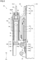
- FIG. 7 illustrates a main part of a rear cushion 20A (hereinafter, may be referred to as a "shock absorber 20A") according to the second embodiment.
- the shock absorber 20A is different from the shock absorber 20 (see FIG. 3 ) in a position where a guide portion 98A is disposed.
- Other basic configurations are the same as those of the shock absorber 20. Components common to those of the shock absorber 20 will be denoted by the same reference numerals, and detailed description thereof will be omitted.
- a sensor 90A constituting an adjustment unit 60A has a substantially semicircular guide portion 98A which guides the core portion 97.
- the guide portion 98A opens parallel to the cylinder 40.
- the rear cushion 20A having the configuration described above also achieves the predetermined effects of the present invention.
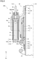
- FIG. 8 illustrates a main part of a rear cushion 20B (hereinafter, may be referred to as a "shock absorber 20B") according to the third embodiment.
- the shock absorber 20B is different from the shock absorber 20 (see FIG. 4 ) in that the shock absorber 20B does not include the guide portion 98 (see FIG. 3 ).
- Other basic configurations are the same as those of the shock absorber 20. Components common to those of the shock absorber 20 will be denoted by the same reference numerals, and detailed description thereof will be omitted.
- a sensor 90B constituting an adjustment unit 60B does not include a guide portion (see reference numeral 98 in FIG. 2 ) which guides the core portion 97.
- the shock absorber 20B having the configuration described above also achieves the predetermined effects of the present invention.
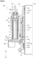
- FIG. 9 illustrates a main part of a rear cushion 20C (hereinafter, may be referred to as a "shock absorber 20C") according to the fourth embodiment.
- a basic configuration of the rear cushion 20C is the same as that of the shock absorber 20.
- Components common to those of the shock absorber 20 will be denoted by the same reference numerals, and detailed description thereof will be omitted.
- the rear cushion 20C includes a spring receiving portion 133 (a receiving member 133) which receives the spring 25, an adjustment unit 60C which adjusts a preload, and a coupling member 140 which couples the spring receiving portion 133 and a sensor 90C of the adjustment unit 60C.
- the spring receiving portion 133 is movable along the axis CL1 relative to an outer circumferential surface of the cylinder main body 42, and is provided to be rotatable around the axis CL1.
- the spring receiving portion 133 includes a cylindrical base portion 133a disposed along the outer circumferential surface of the cylinder main body 42, a spring receiving main body 133b which is a plate-shaped annular portion protruding from the base portion 133a toward an outer side in the radial direction of the cylinder 40 and which comes into contact with an upper end of the spring 25, a second recessed portion 133c (a recessed portion 133c) which is formed on an outer periphery of the spring receiving main body 133b and is recessed toward the axis CL1, and a claw portion 133d which extends downward from a lower end of the base portion 133a and of which a lower end is formed into a claw shape.
- the adjustment unit 60C includes the sensor 90C which detects a position of the spring receiving portion 133.
- the sensor 90C includes a guide portion 98C which guides the core portion 97.
- a position and the like where the guide portion 98C is disposed are the same as those of the guide portion 98 described above (see FIGS. 3 to 5 ), and detailed description thereof will be omitted.
- the shock absorber 20C having the configuration described above also achieves the predetermined effects of the present invention.
- the spring receiving portion 133 includes the second recessed portion 133c over a circumferential direction, and the second recessed portion 133c is formed into a recessed shape toward a center of the spring receiving portion 133 on an outer circumferential edge of the spring receiving portion 133.
- the coupling member 140 includes the second flange portion 143 which protrudes toward the second recessed portion 133c and of which a tip end faces the second recessed portion 133c.
- the core portion 97 is held by the second recessed portion 133c via the second flange portion 143.
- the shock absorber according to the present invention is not limited to such examples.
- the shock absorber according to the present invention is also applicable to a mono-shock type rear cushion, an inverted front fork, and an upright front fork. That is, the shock absorber according to the present invention is not limited to the twin-shock type rear cushion.
- the shock absorber according to the present invention is applicable not only to a two-wheel vehicle but also to a three-wheel vehicle, a buggy, and the like. That is, the present invention can be mounted on a straddle type vehicle other than a two-wheel vehicle.
- the core portion 97 and the coupling members 100 and 140 may be configured to be rotatable around the axis CL2.
- the shock absorber according to the present invention is suitable for a rear cushion of a straddle type vehicle.
Landscapes
- Engineering & Computer Science (AREA)
- Mechanical Engineering (AREA)
- General Engineering & Computer Science (AREA)
- Physics & Mathematics (AREA)
- General Physics & Mathematics (AREA)
- Fluid-Damping Devices (AREA)
- Vehicle Body Suspensions (AREA)
- Axle Suspensions And Sidecars For Cycles (AREA)
Claims (7)
- Stoßdämpfer (20, 20A, 20B, 20C), umfassend:einen Zylinder (40), der mit einem Kolben (53) versehen ist, der entlang einer Achse (CL1) innerhalb des Zylinders (40) beweglich ist;eine Feder (25), die koaxial mit dem Zylinder (40) vorgesehen ist;ein Aufnahmeelement (33, 133), das die Feder (25) aufnimmt und in axialer Richtung des Zylinders (40) beweglich ist;einen Sensor (90, 90A, 90B, 90C), der konfiguriert ist, um eine Position des Aufnahmeelements (33, 133) zu erkennen; undein Kupplungselement (100, 140), das das Aufnahmeelement (33, 133) und den Sensor (90, 90A, 90B, 90C) koppelt, eine Drehung des Aufnahmeelements (33, 133) um die Achse (CL1) ermöglicht und eine Bewegung des Sensors (90, 90A, 90B, 90C) entlang der axialen Richtung ermöglicht, dadurch gekennzeichnet, dass:der Sensor (90, 90A, 90B,90C) einschließteinen Spulenabschnitt (96), der durch Wickeln eines leitenden Drahtes gebildet wird, wobei eine Bewegung des Spulenabschnitts (96) eingeschränkt ist, undeinen Kernabschnitt (97), der zusammen mit dem Kupplungselement (100, 140) entlang der Achse (CL1) beweglich ist, wobei mindestens ein Teil des Kernabschnitts (97) einer Innenseite des Spulenabschnitts (96) zugewandt ist;das Kupplungselement (100, 140) integral mit dem Kernabschnitt (97) ausgebildet ist; undein vertiefter Abschnitt (103, 133c) in einem des Aufnahmeelements (33, 133) und des Kupplungselements (100, 140) ausgebildet ist, ein vorstehender Abschnitt (33c, 143), der dem vertieften Abschnitt (103, 133c) zugewandt ist, in dem anderen von Aufnahmeelement (33, 133) und Kupplungselement (100, 140) ausgebildet ist, und das Aufnahmeelement (33, 133) und das Kupplungselement (100, 140) über den vertieften Abschnitt (103, 133c) und den vorstehenden Abschnitt (33c) miteinander verbunden sind.
- Stoßdämpfer (20, 20A, 20B, 20C) nach Anspruch 1, wobei:das Aufnahmeelement (33, 133) einen ersten Flanschabschnitt (33c) einschließt, der der vorstehende Abschnitt (33c, 143) ist, der in einer ringförmigen Form um die Achse (CL1) herum ausgebildet ist;das Kupplungselement (100, 140) einen ersten vertieften Abschnitt (103) einschließt, der der vertiefte Abschnitt (103, 133c) ist, der in einer vertieften Form ausgebildet ist, um eine Außenkante des ersten Flanschabschnitts (33c) zu umgeben; undder Kernabschnitt (97) vom ersten Flanschabschnitt (33c) über den ersten vertieften Abschnitt (103) gehalten wird.
- Stoßdämpfer (20, 20A, 20B, 20C) nach Anspruch 1, wobei:das Aufnahmeelement (33, 133) einen zweiten vertieften Abschnitt (133c) über eine Umfangsrichtung einschließt, wobei der zweite vertiefte Abschnitt (133c) der vertiefte Abschnitt (103, 133c) ist, der in einer vertieften Form zu einer Mitte an einer äußeren Umfangskante des Aufnahmeelements (33, 133) ausgebildet ist;das Kupplungselement (100, 140) einen zweiten Flanschabschnitt (143) einschließt, der der vorstehende Abschnitt (33c, 143) ist, der in Richtung des zweiten vertieften Abschnitts (133c) vorsteht, und ein Spitzenende des Kupplungselements (100, 140) dem zweiten vertieften Abschnitt (133c) zugewandt ist; undder Kernabschnitt (97) vom zweiten vertieften Abschnitt (133c) über den zweiten Flanschabschnitt (143) gehalten wird.
- Stoßdämpfer (20, 20A, 20B, 20C) nach einem der Ansprüche 1 bis 3, wobei der Sensor (90, 90A, 90B, 90C) sich außerhalb des Zylinders (40) befindet.
- Stoßdämpfer (20, 20A, 20B, 20C) nach einem der Ansprüche 1 bis 4, wobei
der Kernabschnitt (97) eine kreisförmige Querschnittsform aufweist, deren normale Richtung eine axiale Richtung des Kernabschnitts (97) ist. - Stoßdämpfer (20, 20A, 20B, 20C) nach einem der Ansprüche 1 bis 5, wobei:der Sensor (90, 90A, 90B, 90C) einen Führungsabschnitt (98, 98A, 98C) einschließt, der konfiguriert ist, um eine Bewegung des Kernabschnitts (97) entlang der axialen Richtung des Kernabschnitts (97) zu führen; undder Kernabschnitt (97) zwischen dem Führungsabschnitt (98, 98A, 98C) und dem Zylinder (40) angeordnet ist.
- Stoßdämpfer (20, 20A, 20B, 20C) nach Anspruch 6, wobei:der Führungsabschnitt (98, 98A, 98C) in einem Abstand (L1, L2) vom Aufnahmeelement (33, 133) angeordnet ist; undder Abstand (L1, L2) kleiner als ein Durchmesser (D) des Kernabschnitts (97) in einer radialen Richtung des Zylinders (40) ist.
Applications Claiming Priority (2)
| Application Number | Priority Date | Filing Date | Title |
|---|---|---|---|
| PCT/JP2019/028136 WO2021009877A1 (ja) | 2019-07-17 | 2019-07-17 | 緩衝器 |
| PCT/JP2019/041907 WO2021009936A1 (ja) | 2019-07-17 | 2019-10-25 | 緩衝器 |
Publications (3)
| Publication Number | Publication Date |
|---|---|
| EP4001691A1 EP4001691A1 (de) | 2022-05-25 |
| EP4001691A4 EP4001691A4 (de) | 2023-08-02 |
| EP4001691B1 true EP4001691B1 (de) | 2025-05-07 |
Family
ID=69997975
Family Applications (1)
| Application Number | Title | Priority Date | Filing Date |
|---|---|---|---|
| EP19937543.7A Active EP4001691B1 (de) | 2019-07-17 | 2019-10-25 | Stossdämpfer |
Country Status (3)
| Country | Link |
|---|---|
| US (1) | US11745555B2 (de) |
| EP (1) | EP4001691B1 (de) |
| JP (1) | JP6657490B1 (de) |
Families Citing this family (1)
| Publication number | Priority date | Publication date | Assignee | Title |
|---|---|---|---|---|
| JP6657490B1 (ja) * | 2019-07-17 | 2020-03-04 | 株式会社ショーワ | 緩衝器 |
Family Cites Families (14)
| Publication number | Priority date | Publication date | Assignee | Title |
|---|---|---|---|---|
| JPS6053478A (ja) | 1983-09-05 | 1985-03-27 | ヤマハ発動機株式会社 | 自動二輪車等の車高検出機構 |
| JP4936075B2 (ja) * | 2008-04-15 | 2012-05-23 | 株式会社デンソー | 車両駆動用アクチュエータ |
| US9140325B2 (en) * | 2009-03-19 | 2015-09-22 | Fox Factory, Inc. | Methods and apparatus for selective spring pre-load adjustment |
| US8251376B2 (en) * | 2009-07-17 | 2012-08-28 | Shimano Inc. | Bicycle suspension having stroke and damper adjustment |
| JP6012366B2 (ja) | 2012-09-25 | 2016-10-25 | 株式会社ショーワ | 自動二輪車の車高調整装置 |
| JP6546424B2 (ja) | 2015-03-27 | 2019-07-17 | 株式会社ショーワ | フロントフォーク |
| JP6637325B2 (ja) | 2016-02-12 | 2020-01-29 | Kyb株式会社 | 緩衝器 |
| EP3208120A1 (de) * | 2016-02-18 | 2017-08-23 | Haldex Brake Products Aktiebolag | Elektronische steuereinrichtung und steuerkreis für eine luftfederungsanlage eines nutzfahrzeugs |
| EP3208119A1 (de) * | 2016-02-18 | 2017-08-23 | Haldex Brake Products Aktiebolag | Mechanisch betätigte niveauregelventileinrichtung |
| JP6788984B2 (ja) * | 2016-03-28 | 2020-11-25 | Kyb株式会社 | 緩衝器 |
| JP6613189B2 (ja) | 2016-03-28 | 2019-11-27 | Kyb株式会社 | 緩衝器 |
| US10549848B2 (en) * | 2017-04-26 | 2020-02-04 | Safran Landing Systems Canada Inc. | Deployable and retractable shock strut |
| JP6657490B1 (ja) * | 2019-07-17 | 2020-03-04 | 株式会社ショーワ | 緩衝器 |
| KR102591719B1 (ko) * | 2019-08-29 | 2023-10-20 | 현대모비스 주식회사 | 차고 조절장치 |
-
2019
- 2019-10-25 JP JP2019558638A patent/JP6657490B1/ja active Active
- 2019-10-25 EP EP19937543.7A patent/EP4001691B1/de active Active
-
2021
- 2021-12-03 US US17/541,990 patent/US11745555B2/en active Active
Also Published As
| Publication number | Publication date |
|---|---|
| EP4001691A1 (de) | 2022-05-25 |
| EP4001691A4 (de) | 2023-08-02 |
| US11745555B2 (en) | 2023-09-05 |
| JP6657490B1 (ja) | 2020-03-04 |
| JPWO2021009936A1 (ja) | 2021-09-13 |
| US20220088984A1 (en) | 2022-03-24 |
Similar Documents
| Publication | Publication Date | Title |
|---|---|---|
| US9238494B2 (en) | Vehicle | |
| US8905409B2 (en) | Stroke detection device for front fork in motorcycle and motorcycle equipped with stroke detection device | |
| EP1878646A2 (de) | Aufhängungssystem für ein Fahrrad | |
| US20190105958A1 (en) | Shock absorber | |
| EP4001691B1 (de) | Stossdämpfer | |
| US11459058B2 (en) | Suspension for vehicle | |
| US20190047349A1 (en) | Shock absorber | |
| EP2933156B1 (de) | Bremssystem und fahrzeug | |
| CN107850169A (zh) | 缓冲器 | |
| US12291075B2 (en) | Suspension apparatus | |
| US20220163086A1 (en) | Shock absorber | |
| WO2021009877A1 (ja) | 緩衝器 | |
| US12422013B2 (en) | Shock absorber | |
| US12466510B2 (en) | Front fork | |
| KR102270536B1 (ko) | 자기 소버 구조 | |
| US20190111994A1 (en) | Shock absorber | |
| US20240344588A1 (en) | Shock absorber | |
| CN201545136U (zh) | 减震前叉 | |
| JP2009257498A (ja) | 緩衝器のストローク検出装置及び自動二輪車 | |
| WO2025099792A1 (ja) | 懸架装置 | |
| JP2011220494A (ja) | 緩衝器および鞍乗り型車両 | |
| JP6503871B2 (ja) | サスペンション取付装置 | |
| JP2025066076A (ja) | 自転車の重心を状況に応じて変更させる装置及び方法 | |
| JP2021152380A (ja) | 油圧緩衝器 | |
| JP2000274477A (ja) | 二輪車用懸架装置のフロントフォーク |
Legal Events
| Date | Code | Title | Description |
|---|---|---|---|
| STAA | Information on the status of an ep patent application or granted ep patent |
Free format text: STATUS: THE INTERNATIONAL PUBLICATION HAS BEEN MADE |
|
| PUAI | Public reference made under article 153(3) epc to a published international application that has entered the european phase |
Free format text: ORIGINAL CODE: 0009012 |
|
| STAA | Information on the status of an ep patent application or granted ep patent |
Free format text: STATUS: REQUEST FOR EXAMINATION WAS MADE |
|
| 17P | Request for examination filed |
Effective date: 20211206 |
|
| AK | Designated contracting states |
Kind code of ref document: A1 Designated state(s): AL AT BE BG CH CY CZ DE DK EE ES FI FR GB GR HR HU IE IS IT LI LT LU LV MC MK MT NL NO PL PT RO RS SE SI SK SM TR |
|
| DAV | Request for validation of the european patent (deleted) | ||
| DAX | Request for extension of the european patent (deleted) | ||
| A4 | Supplementary search report drawn up and despatched |
Effective date: 20230703 |
|
| RIC1 | Information provided on ipc code assigned before grant |
Ipc: G01D 11/30 20060101ALI20230627BHEP Ipc: B60G 17/02 20060101ALI20230627BHEP Ipc: B60G 11/16 20060101ALI20230627BHEP Ipc: F16F 9/56 20060101ALI20230627BHEP Ipc: F16F 9/32 20060101ALI20230627BHEP Ipc: B62K 25/10 20060101ALI20230627BHEP Ipc: F16F 9/46 20060101AFI20230627BHEP |
|
| GRAP | Despatch of communication of intention to grant a patent |
Free format text: ORIGINAL CODE: EPIDOSNIGR1 |
|
| STAA | Information on the status of an ep patent application or granted ep patent |
Free format text: STATUS: GRANT OF PATENT IS INTENDED |
|
| INTG | Intention to grant announced |
Effective date: 20241213 |
|
| GRAS | Grant fee paid |
Free format text: ORIGINAL CODE: EPIDOSNIGR3 |
|
| GRAA | (expected) grant |
Free format text: ORIGINAL CODE: 0009210 |
|
| STAA | Information on the status of an ep patent application or granted ep patent |
Free format text: STATUS: THE PATENT HAS BEEN GRANTED |
|
| AK | Designated contracting states |
Kind code of ref document: B1 Designated state(s): AL AT BE BG CH CY CZ DE DK EE ES FI FR GB GR HR HU IE IS IT LI LT LU LV MC MK MT NL NO PL PT RO RS SE SI SK SM TR |
|
| REG | Reference to a national code |
Ref country code: GB Ref legal event code: FG4D |
|
| REG | Reference to a national code |
Ref country code: CH Ref legal event code: EP |
|
| REG | Reference to a national code |
Ref country code: DE Ref legal event code: R096 Ref document number: 602019069820 Country of ref document: DE |
|
| REG | Reference to a national code |
Ref country code: IE Ref legal event code: FG4D |
|
| REG | Reference to a national code |
Ref country code: NL Ref legal event code: MP Effective date: 20250507 |
|
| PG25 | Lapsed in a contracting state [announced via postgrant information from national office to epo] |
Ref country code: FI Free format text: LAPSE BECAUSE OF FAILURE TO SUBMIT A TRANSLATION OF THE DESCRIPTION OR TO PAY THE FEE WITHIN THE PRESCRIBED TIME-LIMIT Effective date: 20250507 Ref country code: PT Free format text: LAPSE BECAUSE OF FAILURE TO SUBMIT A TRANSLATION OF THE DESCRIPTION OR TO PAY THE FEE WITHIN THE PRESCRIBED TIME-LIMIT Effective date: 20250908 Ref country code: ES Free format text: LAPSE BECAUSE OF FAILURE TO SUBMIT A TRANSLATION OF THE DESCRIPTION OR TO PAY THE FEE WITHIN THE PRESCRIBED TIME-LIMIT Effective date: 20250507 |
|
| REG | Reference to a national code |
Ref country code: LT Ref legal event code: MG9D |
|
| PG25 | Lapsed in a contracting state [announced via postgrant information from national office to epo] |
Ref country code: GR Free format text: LAPSE BECAUSE OF FAILURE TO SUBMIT A TRANSLATION OF THE DESCRIPTION OR TO PAY THE FEE WITHIN THE PRESCRIBED TIME-LIMIT Effective date: 20250808 Ref country code: NO Free format text: LAPSE BECAUSE OF FAILURE TO SUBMIT A TRANSLATION OF THE DESCRIPTION OR TO PAY THE FEE WITHIN THE PRESCRIBED TIME-LIMIT Effective date: 20250807 |
|
| PG25 | Lapsed in a contracting state [announced via postgrant information from national office to epo] |
Ref country code: NL Free format text: LAPSE BECAUSE OF FAILURE TO SUBMIT A TRANSLATION OF THE DESCRIPTION OR TO PAY THE FEE WITHIN THE PRESCRIBED TIME-LIMIT Effective date: 20250507 Ref country code: PL Free format text: LAPSE BECAUSE OF FAILURE TO SUBMIT A TRANSLATION OF THE DESCRIPTION OR TO PAY THE FEE WITHIN THE PRESCRIBED TIME-LIMIT Effective date: 20250507 |
|
| PGFP | Annual fee paid to national office [announced via postgrant information from national office to epo] |
Ref country code: IT Payment date: 20250922 Year of fee payment: 7 |
|
| REG | Reference to a national code |
Ref country code: AT Ref legal event code: MK05 Ref document number: 1792750 Country of ref document: AT Kind code of ref document: T Effective date: 20250507 |
|
| PG25 | Lapsed in a contracting state [announced via postgrant information from national office to epo] |
Ref country code: BG Free format text: LAPSE BECAUSE OF FAILURE TO SUBMIT A TRANSLATION OF THE DESCRIPTION OR TO PAY THE FEE WITHIN THE PRESCRIBED TIME-LIMIT Effective date: 20250507 |
|
| PGFP | Annual fee paid to national office [announced via postgrant information from national office to epo] |
Ref country code: GB Payment date: 20250904 Year of fee payment: 7 |
|
| PG25 | Lapsed in a contracting state [announced via postgrant information from national office to epo] |
Ref country code: HR Free format text: LAPSE BECAUSE OF FAILURE TO SUBMIT A TRANSLATION OF THE DESCRIPTION OR TO PAY THE FEE WITHIN THE PRESCRIBED TIME-LIMIT Effective date: 20250507 |
|
| PG25 | Lapsed in a contracting state [announced via postgrant information from national office to epo] |
Ref country code: AT Free format text: LAPSE BECAUSE OF FAILURE TO SUBMIT A TRANSLATION OF THE DESCRIPTION OR TO PAY THE FEE WITHIN THE PRESCRIBED TIME-LIMIT Effective date: 20250507 |
|
| PG25 | Lapsed in a contracting state [announced via postgrant information from national office to epo] |
Ref country code: RS Free format text: LAPSE BECAUSE OF FAILURE TO SUBMIT A TRANSLATION OF THE DESCRIPTION OR TO PAY THE FEE WITHIN THE PRESCRIBED TIME-LIMIT Effective date: 20250807 |
|
| PG25 | Lapsed in a contracting state [announced via postgrant information from national office to epo] |
Ref country code: IS Free format text: LAPSE BECAUSE OF FAILURE TO SUBMIT A TRANSLATION OF THE DESCRIPTION OR TO PAY THE FEE WITHIN THE PRESCRIBED TIME-LIMIT Effective date: 20250907 |
|
| PG25 | Lapsed in a contracting state [announced via postgrant information from national office to epo] |
Ref country code: LV Free format text: LAPSE BECAUSE OF FAILURE TO SUBMIT A TRANSLATION OF THE DESCRIPTION OR TO PAY THE FEE WITHIN THE PRESCRIBED TIME-LIMIT Effective date: 20250507 |
|
| PGFP | Annual fee paid to national office [announced via postgrant information from national office to epo] |
Ref country code: DE Payment date: 20250902 Year of fee payment: 7 |
|
| PG25 | Lapsed in a contracting state [announced via postgrant information from national office to epo] |
Ref country code: DK Free format text: LAPSE BECAUSE OF FAILURE TO SUBMIT A TRANSLATION OF THE DESCRIPTION OR TO PAY THE FEE WITHIN THE PRESCRIBED TIME-LIMIT Effective date: 20250507 Ref country code: SM Free format text: LAPSE BECAUSE OF FAILURE TO SUBMIT A TRANSLATION OF THE DESCRIPTION OR TO PAY THE FEE WITHIN THE PRESCRIBED TIME-LIMIT Effective date: 20250507 |
|
| PG25 | Lapsed in a contracting state [announced via postgrant information from national office to epo] |
Ref country code: CZ Free format text: LAPSE BECAUSE OF FAILURE TO SUBMIT A TRANSLATION OF THE DESCRIPTION OR TO PAY THE FEE WITHIN THE PRESCRIBED TIME-LIMIT Effective date: 20250507 |
|
| PG25 | Lapsed in a contracting state [announced via postgrant information from national office to epo] |
Ref country code: EE Free format text: LAPSE BECAUSE OF FAILURE TO SUBMIT A TRANSLATION OF THE DESCRIPTION OR TO PAY THE FEE WITHIN THE PRESCRIBED TIME-LIMIT Effective date: 20250507 |
|
| PG25 | Lapsed in a contracting state [announced via postgrant information from national office to epo] |
Ref country code: RO Free format text: LAPSE BECAUSE OF FAILURE TO SUBMIT A TRANSLATION OF THE DESCRIPTION OR TO PAY THE FEE WITHIN THE PRESCRIBED TIME-LIMIT Effective date: 20250507 Ref country code: SK Free format text: LAPSE BECAUSE OF FAILURE TO SUBMIT A TRANSLATION OF THE DESCRIPTION OR TO PAY THE FEE WITHIN THE PRESCRIBED TIME-LIMIT Effective date: 20250507 |
|
| REG | Reference to a national code |
Ref country code: DE Ref legal event code: R097 Ref document number: 602019069820 Country of ref document: DE |
|
| PLBE | No opposition filed within time limit |
Free format text: ORIGINAL CODE: 0009261 |
|
| STAA | Information on the status of an ep patent application or granted ep patent |
Free format text: STATUS: NO OPPOSITION FILED WITHIN TIME LIMIT |
|
| REG | Reference to a national code |
Ref country code: CH Ref legal event code: L10 Free format text: ST27 STATUS EVENT CODE: U-0-0-L10-L00 (AS PROVIDED BY THE NATIONAL OFFICE) Effective date: 20260318 |
|
| 26N | No opposition filed |
Effective date: 20260210 |