EP4001702A1 - Ölsammler für eine drehmomentübertragungsvorrichtung eines luftfahrzeug-turbotriebwerks - Google Patents
Ölsammler für eine drehmomentübertragungsvorrichtung eines luftfahrzeug-turbotriebwerks Download PDFInfo
- Publication number
- EP4001702A1 EP4001702A1 EP21206907.4A EP21206907A EP4001702A1 EP 4001702 A1 EP4001702 A1 EP 4001702A1 EP 21206907 A EP21206907 A EP 21206907A EP 4001702 A1 EP4001702 A1 EP 4001702A1
- Authority
- EP
- European Patent Office
- Prior art keywords
- oil
- collector
- oil collector
- wall
- recuperator
- Prior art date
- Legal status (The legal status is an assumption and is not a legal conclusion. Google has not performed a legal analysis and makes no representation as to the accuracy of the status listed.)
- Pending
Links
- 230000005540 biological transmission Effects 0.000 title claims abstract description 21
- 238000005192 partition Methods 0.000 claims description 17
- 238000005119 centrifugation Methods 0.000 claims description 4
- 239000003921 oil Substances 0.000 description 56
- 239000003638 chemical reducing agent Substances 0.000 description 21
- 230000001050 lubricating effect Effects 0.000 description 4
- 238000005461 lubrication Methods 0.000 description 4
- 239000000463 material Substances 0.000 description 4
- 238000011144 upstream manufacturing Methods 0.000 description 3
- 238000010438 heat treatment Methods 0.000 description 2
- 238000004064 recycling Methods 0.000 description 2
- 238000010521 absorption reaction Methods 0.000 description 1
- 239000011324 bead Substances 0.000 description 1
- 230000005587 bubbling Effects 0.000 description 1
- 230000015556 catabolic process Effects 0.000 description 1
- 238000002485 combustion reaction Methods 0.000 description 1
- 150000001875 compounds Chemical class 0.000 description 1
- 238000006731 degradation reaction Methods 0.000 description 1
- 230000002706 hydrostatic effect Effects 0.000 description 1
- 230000010354 integration Effects 0.000 description 1
- QWXYZCJEXYQNEI-OSZHWHEXSA-N intermediate I Chemical compound COC(=O)[C@@]1(C=O)[C@H]2CC=[N+](C\C2=C\C)CCc2c1[nH]c1ccccc21 QWXYZCJEXYQNEI-OSZHWHEXSA-N 0.000 description 1
- 239000010687 lubricating oil Substances 0.000 description 1
- 230000014759 maintenance of location Effects 0.000 description 1
- 238000004513 sizing Methods 0.000 description 1
- 238000009423 ventilation Methods 0.000 description 1
- 239000011800 void material Substances 0.000 description 1
Images



Classifications
-
- F—MECHANICAL ENGINEERING; LIGHTING; HEATING; WEAPONS; BLASTING
- F16—ENGINEERING ELEMENTS AND UNITS; GENERAL MEASURES FOR PRODUCING AND MAINTAINING EFFECTIVE FUNCTIONING OF MACHINES OR INSTALLATIONS; THERMAL INSULATION IN GENERAL
- F16H—GEARING
- F16H57/00—General details of gearing
- F16H57/04—Features relating to lubrication or cooling or heating
- F16H57/0467—Elements of gearings to be lubricated, cooled or heated
- F16H57/0479—Gears or bearings on planet carriers
-
- F—MECHANICAL ENGINEERING; LIGHTING; HEATING; WEAPONS; BLASTING
- F01—MACHINES OR ENGINES IN GENERAL; ENGINE PLANTS IN GENERAL; STEAM ENGINES
- F01D—NON-POSITIVE DISPLACEMENT MACHINES OR ENGINES, e.g. STEAM TURBINES
- F01D25/00—Component parts, details, or accessories, not provided for in, or of interest apart from, other groups
- F01D25/18—Lubricating arrangements
-
- F—MECHANICAL ENGINEERING; LIGHTING; HEATING; WEAPONS; BLASTING
- F01—MACHINES OR ENGINES IN GENERAL; ENGINE PLANTS IN GENERAL; STEAM ENGINES
- F01D—NON-POSITIVE DISPLACEMENT MACHINES OR ENGINES, e.g. STEAM TURBINES
- F01D15/00—Adaptations of machines or engines for special use; Combinations of engines with devices driven thereby
- F01D15/12—Combinations with mechanical gearing
-
- F—MECHANICAL ENGINEERING; LIGHTING; HEATING; WEAPONS; BLASTING
- F02—COMBUSTION ENGINES; HOT-GAS OR COMBUSTION-PRODUCT ENGINE PLANTS
- F02C—GAS-TURBINE PLANTS; AIR INTAKES FOR JET-PROPULSION PLANTS; CONTROLLING FUEL SUPPLY IN AIR-BREATHING JET-PROPULSION PLANTS
- F02C7/00—Features, components parts, details or accessories, not provided for in, or of interest apart form groups F02C1/00 - F02C6/00; Air intakes for jet-propulsion plants
- F02C7/36—Power transmission arrangements between the different shafts of the gas turbine plant, or between the gas-turbine plant and the power user
-
- F—MECHANICAL ENGINEERING; LIGHTING; HEATING; WEAPONS; BLASTING
- F16—ENGINEERING ELEMENTS AND UNITS; GENERAL MEASURES FOR PRODUCING AND MAINTAINING EFFECTIVE FUNCTIONING OF MACHINES OR INSTALLATIONS; THERMAL INSULATION IN GENERAL
- F16H—GEARING
- F16H57/00—General details of gearing
- F16H57/04—Features relating to lubrication or cooling or heating
- F16H57/0409—Features relating to lubrication or cooling or heating characterised by increasing efficiency, e.g. by reducing splash losses
-
- F—MECHANICAL ENGINEERING; LIGHTING; HEATING; WEAPONS; BLASTING
- F16—ENGINEERING ELEMENTS AND UNITS; GENERAL MEASURES FOR PRODUCING AND MAINTAINING EFFECTIVE FUNCTIONING OF MACHINES OR INSTALLATIONS; THERMAL INSULATION IN GENERAL
- F16H—GEARING
- F16H57/00—General details of gearing
- F16H57/04—Features relating to lubrication or cooling or heating
- F16H57/042—Guidance of lubricant
- F16H57/0427—Guidance of lubricant on rotary parts, e.g. using baffles for collecting lubricant by centrifugal force
-
- F—MECHANICAL ENGINEERING; LIGHTING; HEATING; WEAPONS; BLASTING
- F16—ENGINEERING ELEMENTS AND UNITS; GENERAL MEASURES FOR PRODUCING AND MAINTAINING EFFECTIVE FUNCTIONING OF MACHINES OR INSTALLATIONS; THERMAL INSULATION IN GENERAL
- F16H—GEARING
- F16H57/00—General details of gearing
- F16H57/04—Features relating to lubrication or cooling or heating
- F16H57/042—Guidance of lubricant
- F16H57/043—Guidance of lubricant within rotary parts, e.g. axial channels or radial openings in shafts
-
- F—MECHANICAL ENGINEERING; LIGHTING; HEATING; WEAPONS; BLASTING
- F16—ENGINEERING ELEMENTS AND UNITS; GENERAL MEASURES FOR PRODUCING AND MAINTAINING EFFECTIVE FUNCTIONING OF MACHINES OR INSTALLATIONS; THERMAL INSULATION IN GENERAL
- F16H—GEARING
- F16H57/00—General details of gearing
- F16H57/04—Features relating to lubrication or cooling or heating
- F16H57/048—Type of gearings to be lubricated, cooled or heated
- F16H57/0482—Gearings with gears having orbital motion
- F16H57/0486—Gearings with gears having orbital motion with fixed gear ratio
-
- F—MECHANICAL ENGINEERING; LIGHTING; HEATING; WEAPONS; BLASTING
- F05—INDEXING SCHEMES RELATING TO ENGINES OR PUMPS IN VARIOUS SUBCLASSES OF CLASSES F01-F04
- F05D—INDEXING SCHEME FOR ASPECTS RELATING TO NON-POSITIVE-DISPLACEMENT MACHINES OR ENGINES, GAS-TURBINES OR JET-PROPULSION PLANTS
- F05D2220/00—Application
- F05D2220/30—Application in turbines
- F05D2220/32—Application in turbines in gas turbines
- F05D2220/323—Application in turbines in gas turbines for aircraft propulsion, e.g. jet engines
-
- F—MECHANICAL ENGINEERING; LIGHTING; HEATING; WEAPONS; BLASTING
- F05—INDEXING SCHEMES RELATING TO ENGINES OR PUMPS IN VARIOUS SUBCLASSES OF CLASSES F01-F04
- F05D—INDEXING SCHEME FOR ASPECTS RELATING TO NON-POSITIVE-DISPLACEMENT MACHINES OR ENGINES, GAS-TURBINES OR JET-PROPULSION PLANTS
- F05D2260/00—Function
- F05D2260/40—Transmission of power
- F05D2260/403—Transmission of power through the shape of the drive components
- F05D2260/4031—Transmission of power through the shape of the drive components as in toothed gearing
- F05D2260/40311—Transmission of power through the shape of the drive components as in toothed gearing of the epicyclical, planetary or differential type
-
- F—MECHANICAL ENGINEERING; LIGHTING; HEATING; WEAPONS; BLASTING
- F05—INDEXING SCHEMES RELATING TO ENGINES OR PUMPS IN VARIOUS SUBCLASSES OF CLASSES F01-F04
- F05D—INDEXING SCHEME FOR ASPECTS RELATING TO NON-POSITIVE-DISPLACEMENT MACHINES OR ENGINES, GAS-TURBINES OR JET-PROPULSION PLANTS
- F05D2260/00—Function
- F05D2260/98—Lubrication
-
- F—MECHANICAL ENGINEERING; LIGHTING; HEATING; WEAPONS; BLASTING
- F16—ENGINEERING ELEMENTS AND UNITS; GENERAL MEASURES FOR PRODUCING AND MAINTAINING EFFECTIVE FUNCTIONING OF MACHINES OR INSTALLATIONS; THERMAL INSULATION IN GENERAL
- F16H—GEARING
- F16H57/00—General details of gearing
- F16H57/04—Features relating to lubrication or cooling or heating
- F16H57/0456—Lubrication by injection; Injection nozzles or tubes therefor
-
- F—MECHANICAL ENGINEERING; LIGHTING; HEATING; WEAPONS; BLASTING
- F16—ENGINEERING ELEMENTS AND UNITS; GENERAL MEASURES FOR PRODUCING AND MAINTAINING EFFECTIVE FUNCTIONING OF MACHINES OR INSTALLATIONS; THERMAL INSULATION IN GENERAL
- F16H—GEARING
- F16H57/00—General details of gearing
- F16H57/08—General details of gearing of gearings with members having orbital motion
- F16H57/082—Planet carriers
-
- Y—GENERAL TAGGING OF NEW TECHNOLOGICAL DEVELOPMENTS; GENERAL TAGGING OF CROSS-SECTIONAL TECHNOLOGIES SPANNING OVER SEVERAL SECTIONS OF THE IPC; TECHNICAL SUBJECTS COVERED BY FORMER USPC CROSS-REFERENCE ART COLLECTIONS [XRACs] AND DIGESTS
- Y02—TECHNOLOGIES OR APPLICATIONS FOR MITIGATION OR ADAPTATION AGAINST CLIMATE CHANGE
- Y02T—CLIMATE CHANGE MITIGATION TECHNOLOGIES RELATED TO TRANSPORTATION
- Y02T50/00—Aeronautics or air transport
- Y02T50/60—Efficient propulsion technologies, e.g. for aircraft
Definitions
- the invention relates to an oil collector for a torque transmission device of an aircraft turbine engine.
- the role of a torque transmission device such as a mechanical reducer, for example of the type described in the document FR-A1-3 076 853 , is to change the speed and torque ratio between the input axis and the output axis of a mechanical system.
- the state of the art also includes documents FR-A1-2 942 284 , FR-A1-2 987 416 , FR-A1-3 008 462 , FR-A1-3 008 463 , FR-A1-3 041 054 , FR-A1-3 065 773 , FR-A1-3 073 915 and FR-A1-3 092 889 , as well as the documents WO-A1-2019/141920 , EP-A1-2 719 927 and WO-A1-2011/129076
- the new generations of dual-flow turbomachines include a mechanical reduction gear to drive the shaft of a fan (also called a "fan").
- a mechanical reduction gear to drive the shaft of a fan also called a "fan”
- the purpose of the reducer is to transform the so-called fast speed of rotation of the shaft of a power turbine into a slower speed of rotation for the shaft driving the fan.
- Such a reducer comprises a central pinion, called sun gear, a crown and pinions called satellites, which are engaged between the sun gear and the crown.
- the satellites are held by a frame called the planet carrier.
- the sun gear, the crown and the planet carrier are planetary because their axes of revolution coincide with the longitudinal axis X of the turbomachine.
- the satellites each have a different axis of revolution and are evenly distributed over the same operating diameter around the axis of the planetary gears. These axes are parallel to the longitudinal axis X.
- Reducers can be composed of one or more meshing stages. This meshing is ensured in different ways such as by contact, by friction or even by magnetic fields. There are several types of meshing by contact as with straight or chevron teeth.
- Gearbox gears are lubricated with oil.
- the lubricating oil is heated during operation because it absorbs heat energy generated by the gearbox.
- the temperature of the oil has an impact on its viscosity and on its lubricating efficiency. It is therefore important to evacuate the hot oil after the lubrication of the reducer, in order to recycle it.
- a solution to this problem consists in placing deflectors or oil collectors between the satellites.
- the purpose of the deflectors is to deflect the projected oil towards means of evacuation and recycling of the oil.
- the oil collectors are intended to collect the projected oil and to convey it towards the means of evacuation and recycling of the oil.
- the present invention proposes a solution to at least some of the problems mentioned above.
- the integration of a lattice structure at the level of the wall of the collector allows a level of porosity which slows down more or less intensely the flow of oil and thus makes it possible to recover the oil centrifuged by the satellites to evacuate it "calmly » via the inside of the collector and prevent it from being re-mixed between the teeth.
- the invention thus makes it possible to improve the evacuation of oil while reducing the risk of the appearance of beads.
- the invention thus makes it possible in particular to ensure good oil suction, to reduce the losses by transfer of momentum, to reduce the mass temperature of the teeth, to reduce the heating of the components of the device and to increase the margin to seizing.
- the invention also relates to a torque transmission device for an aircraft turbomachine, this device comprising meshed teeth and at least one oil collector as described above, which is arranged next to a toothing or interposed between two gears and which is configured to collect oil projected by centrifugation by at least one of these gears.
- each of said external walls extending at least in part around one of the teeth and an axis of revolution of this teeth.
- the device is, for example, an epicyclic or planetary reduction gear, an accessory box, or a gear box.
- the invention also relates to a turbine engine, in particular for an aircraft, comprising an oil collector or device as described previously.
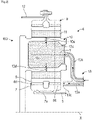
- the figure 1 describes a turbomachine 1 which comprises, in a conventional manner, a fan S, a low pressure compressor 1a, a high pressure compressor 1b, an annular combustion chamber 1c, a high pressure turbine 1d, a low pressure turbine 1e and a nozzle of 1 hour exhaust.
- the high pressure compressor 1b and the high pressure turbine 1d are connected by a high pressure shaft 2 and form with it a high pressure body (HP).
- the low pressure compressor 1a and the low pressure turbine 1e are connected by a low pressure shaft 3 and form with it a low pressure body (LP).
- the fan S is driven by a fan shaft 4 which is driven to the LP shaft 3 by means of a torque transmission device 100, in particular a reducer 6.
- This reducer 6 is generally of the planetary or planetary type.
- the reducer 6 is positioned in the upstream part of the turbine engine 1.
- a fixed structure comprising schematically, here, an upstream part 5a and a downstream part 5b which makes up the motor casing or stator 5 is arranged so as to form an enclosure E surrounding the reducer 6.
- This enclosure E is here closed upstream by seals at the level of a bearing allowing the crossing of the fan shaft 4, and downstream by seals at the level of the crossing of the LP shaft 3.
- the figure 2 and 3 show a reducer 6 which can take the form of different architectures depending on whether certain parts are fixed or rotating.
- the reducer 6 is connected to the BP shaft 3, for example via internal splines 7a.
- the BP shaft 3 drives a planet gear called the sun gear 7.
- the sun gear 7, whose axis of rotation coincides with that of the turbomachine X drives a series of gears called satellites 8, 8', which are evenly distributed over the same diameter around the axis of rotation X.
- Each satellite 8, 8' has teeth 8d, 8d' on its circumference. This diameter is equal to twice the operating center distance between the solar 7 and the satellites 8, 8'.
- the number of satellites 8, 8' is generally defined between three and seven for this type of application.
- the set of satellites 8, 8' is held by a frame called the planet carrier 10.
- Each satellite 8, 8' rotates around its own axis Y, Y', and meshes with crown 9.
- Each satellite 8, 8' is mounted free to rotate using a bearing 11, for example of the bearing or hydrostatic bearing type.
- the arrows of the picture 2 describe the routing of the oil in the reducer 6.
- the oil arrives in the reducer 6 from the stator part 5 in the distributor 13 by various means which will not be specified in this view because they are specific to one or more types of architecture.
- the distributor 13 is separated into 2 parts, each generally repeated with the same number of satellites 8, 8'.
- the injectors 13a have the function of lubricating the teeth 8d, 8d and the arms 13b have the function of lubricating the bearings 11.
- the oil is brought to the injectors 13a to come out through the ends 13c in order to lubricate with oil called cold ( HF ) the toothings 8d, 8d' of the satellites 8, 8', of the sun gear 7 and also of the ring gear 9.
- oil is brought to the injectors 13a to come out through the ends 13c in order to lubricate with oil called cold ( HF ) the toothings 8d, 8d' of the satellites 8, 8', of the sun gear 7
- the oil is also brought to the arm 13b and circulates via the supply mouth 13d of the bearing 11.
- the oil then circulates through the axle in one or more buffer zones 10c and then exits through the orifices 10d in order to lubricate the bearings 11 of the satellites 8, 8'.
- the reducer 6 comprises at least one oil collector 20 arranged next to a toothing 8d, 8d' or interposed between two toothings 8d, 8d', c' that is to say here the teeth 8d, 8d′ of the satellites 8, 8′.
- the picture 3 represents a single collector 20
- the reducer 6 comprises a collector 20 between two adjacent satellites 8, 8' and therefore comprises as many collectors 20 as there are satellites 8, 8', namely four in the example shown.
- the figure 4 , 5 , 6 represent two satellites 8, 8 'adjacent to the reducer 6 located on either side of one of the oil collectors 20.
- the oil collector 20 is configured to collect projected oil, in particular projected by centrifugation by at least one of the toothings 8d, 8d' belonging here to the satellites 8, 8'.
- the collector 20 comprises at least one wall 30, 30', in particular having a constant thickness, and here two walls 30, 30' which are in particular at a distance from each other and for example intercalated between two teeth 8d, 8d ' adjacent.
- the term "wall” means an outer wall which therefore extends outside the collector and can be directly exposed to an oil jet. Each of the walls therefore has an outer surface defining an outer surface of the collector.
- the two walls 30, 30' are in particular independent, the collector 20 having for example a general I shape and the walls 30, 30' extending laterally on the two longest sides of this I. These walls 30, 30 'have in particular surfaces 31, 31' curved convex opposite one another.
- Each wall 30, 30' has for example a generally curved shape and extends in particular respectively at least in part around the toothing 8d, 8d' in front of which it is located and an axis of revolution Y, Y' of this toothing 8d, 8d'.
- Each of the walls 30, 30' is in particular respectively formed at least in part by a lattice structure 50, also called a lattice.
- the lattice structure 50 notably has a constant thickness.
- the lattice structure 50 is in particular formed by a mesh 51.
- This mesh 51 may have a constant form or composition or, on the contrary, which varies.
- the grid 51 is composed of patterns 50a or parallelepiped meshes such as rectangles or squares.
- the lattice structure 50 is in particular formed by the spatial repetition, either for the material or for the void, of a single pattern or mesh 50a.
- the pattern 50a is in particular produced by the interconnection of simple shapes to be chosen in particular from spheres or ovoids and bars of constant (or variable) section, in particular circles, rectangles or octagons.
- the pattern 50a is arranged so that the voids between the material communicate so as to organize paths through the material for the passage of oil.
- Collector 20 also includes at least one recuperator 40a, 40b located at one end 30a, 30a', 30b, 30b' of wall 30, 30'.
- the collector 20 here comprises two recuperators 40a, 40b.
- a first 40a of recuperators extends between first ends 30a, 30a' of the two walls 30, 30' and at one end of the I-shape, and a second 40b of recuperators extends between second ends 30b, 30b' opposite these walls 30, 30' and at an opposite end of the I-shape.
- the recuperators 40a, 40b are configured to recover the oil captured by the walls 30, 30' and intended to flow from the walls 30, 30' to each of the recuperators 40a, 40b.
- the recuperators 40a, 40b have in particular a general U shape.
- the recuperators 40a, 40b comprise a bottom partition 41a, 41b which extends between two side partitions 42a, 42a', 42b, 42b'.
- the side partitions 42a, 42a', 42b, 42b' each have a generally curved shape and extend in the extension of the walls 30, 30'.
- the side partitions 42a, 42a', 42b, 42b' of the same wall 30, 30' are therefore also curved convex opposite one another.
- Each side partition 42a, 42a', 42b, 42b' has a generally curved shape and extends respectively in part around the toothing 8d, 8d' situated in lifelong screw and the axis of revolution Y, Y' of this toothing 8d, 8d'.
- the side partitions 42a, 42a', 42b, 42b' form with the bottom partition 41a, 41b the U-shape of each recuperator 40a, 40b.
- the side wall 42a of the first recuperator 40a in an extension of the wall 30 is the side wall 42a of the first recuperator 40a, the end 30a being between the wall 30 and the side wall 42a.
- the side wall 42b of the second recuperator 40b In the opposite extension of the wall 30 is the side wall 42b of the second recuperator 40b, the end 30b being between the wall 30 and the side wall 42b.
- Collector 20 thus has a cavity formed by walls 30, 30' and recuperators 40a, 40b.
- the oil projected by the teeth 8d, 8d′, penetrates into the material of the lattice structure 50 of the wall 30, 30′.
- the oil is then slowed down and flows through the lattice structure 50 and crosses the surfaces 31, 31' of the walls 30, 30' of the collector 20 in a direction referenced F.
- the oil is then directed towards the recuperator 40a , 40b of the collector 20 in a direction referenced F'.
- the oil (referenced 55 during its passage over the recuperator 40a, 40b) will then be evacuated.
- Each of the patterns 50a comprises in particular bars 52 interconnected.
- This pattern 50a occupies in particular a volume in the shape of a parallelepiped, in particular a rectangular parallelepiped having a long side L, an intermediate side I and a short side c.
- Some 52' of the bars 52 extend along edges 54 of this pattern 50a, here four bars 52' extend along four edges 54 of this pattern 50a, in particular the four edges 54 forming the largest dimension long L of the rectangular parallelepiped.
- Certain 52" of the bars 52 extend along faces of this pattern 50a, here four bars 52" extend along four faces of this pattern 50a, in particular on the faces forming the longest dimension of the rectangular parallelepiped , that is to say the two faces formed by the long dimensions L and intermediate I and the two faces formed by the long dimensions L and short c, for example by connecting together two of the vertices of the same face of the rectangular parallelepiped by describing a diagonal on each of the faces.
- the lattice structure 50 thus comprises here eight bars 52.
- Each of the bars 52 is terminated by a ball 53, located at a vertex of the rectangular parallelepiped.
- Several bars 52 can end with the same ball 53 if these bars end on the same vertex of the rectangular parallelepiped.
- the lattice structure 50 here comprises eight balls 53, that is to say a ball at each vertex of the rectangular parallelepiped.
- patterns 50a A particular example of patterns 50a has been described here but it is obvious that the lattice structure 50 can take an infinite number of shapes. There is indeed an infinity of patterns 50a that could be used instead of the one described here, more or less efficient depending on their shape.
- the trellis structure 50 makes it possible to recover the oil from the reducer 6 to then allow it to be evacuated gently.
- the level of porosity of the structure 50 makes it possible to slow down the flow of oil more or less intensely depending on the needs.
- the patterns 50a can also be oriented, in particular thanks to the positioning of the various bars 52.
- the patterns 50a can thus be produced by favoring a certain direction, making it possible to effectively recover the oil while preventing it from overflowing. It is for example possible to define the “absorption” gain as a function of the geometry of the lattice structure 50 in order to best improve the lubrication.
- the device 100 of the invention is in particular a reduction gear 6 with an epicyclic or planetary gear train.
- This device 100 could also be an accessory box also named by the English acronym AGB designating the Anglo-Saxon terms “ Accessory Gear Box ”, or a gear box also named by the English acronym RGB designating the Anglo-Saxon terms. Saxon “ Reduction Gear Box ". It could also be integrated into "straight" walls as a simple deflector.
- the invention also relates to a turbine engine 1, in particular of an aircraft, comprising an oil collector 20 as described above.
- the invention provides several advantages and in particular makes it possible to ensure good oil suction, to reduce losses by transfer of quantity of movement, to reduce the mass temperature of the satellites 8, 8' and the heating of the components and to increase the seizing margin.
Landscapes
- Engineering & Computer Science (AREA)
- General Engineering & Computer Science (AREA)
- Mechanical Engineering (AREA)
- Chemical & Material Sciences (AREA)
- Combustion & Propulsion (AREA)
- General Details Of Gearings (AREA)
Applications Claiming Priority (1)
| Application Number | Priority Date | Filing Date | Title |
|---|---|---|---|
| FR2011728A FR3116318B1 (fr) | 2020-11-16 | 2020-11-16 | Collecteur d’huile pour un dispositif de transmission de couple d’une turbomachine d’aéronef |
Publications (1)
| Publication Number | Publication Date |
|---|---|
| EP4001702A1 true EP4001702A1 (de) | 2022-05-25 |
Family
ID=74183399
Family Applications (1)
| Application Number | Title | Priority Date | Filing Date |
|---|---|---|---|
| EP21206907.4A Pending EP4001702A1 (de) | 2020-11-16 | 2021-11-08 | Ölsammler für eine drehmomentübertragungsvorrichtung eines luftfahrzeug-turbotriebwerks |
Country Status (3)
| Country | Link |
|---|---|
| US (1) | US11686217B2 (de) |
| EP (1) | EP4001702A1 (de) |
| FR (1) | FR3116318B1 (de) |
Citations (11)
| Publication number | Priority date | Publication date | Assignee | Title |
|---|---|---|---|---|
| FR2942284A1 (fr) | 2009-02-16 | 2010-08-20 | Snecma | Lubrification et refroidissement d'un reducteur a train d'engrenages epicycloidal |
| WO2011129076A1 (ja) | 2010-04-13 | 2011-10-20 | 川崎重工業株式会社 | 遊星歯車装置 |
| FR2987416A1 (fr) | 2012-02-23 | 2013-08-30 | Snecma | Dispositif de lubrification d'un reducteur epicycloidal. |
| EP2719927A1 (de) | 2012-10-12 | 2014-04-16 | Rolls-Royce plc | Ölrücklaufanordnung |
| FR3008462A1 (fr) | 2013-07-10 | 2015-01-16 | Hispano Suiza Sa | Integration d'un train d'engrenages dans un voile de pignon de boitier d'entrainement pour turbomachine |
| FR3008463A1 (fr) | 2013-07-10 | 2015-01-16 | Hispano Suiza Sa | Structure compacte de boitier d'entrainement pour turbomachine d'aeronef |
| FR3041054A1 (fr) | 2015-09-15 | 2017-03-17 | Hispano-Suiza | Dispositif d'alimentation en huile pour un reducteur a train epicycloidal. |
| FR3065773A1 (fr) | 2017-04-27 | 2018-11-02 | Safran Transmission Systems | Porte-satellites a cage pour un reducteur de vitesse a train epicycloidal |
| FR3073915A1 (fr) | 2017-11-17 | 2019-05-24 | Safran Transmission Systems | Cage de reducteur de vitesse a train planetaire ou epicycloidal de turbomachine |
| FR3076853A1 (fr) | 2018-01-16 | 2019-07-19 | Safran Transmission Systems | Collecteur d'huile pour reducteur de vitesse notamment de turbomachine, reducteur de vitesse et turbomachine associes |
| FR3092889A1 (fr) | 2019-02-14 | 2020-08-21 | Safran Transmission Systems | Lubrification d’un porte-satellites pour un reducteur mecanique de turbomachine, en particulier d’aeronef |
Family Cites Families (3)
| Publication number | Priority date | Publication date | Assignee | Title |
|---|---|---|---|---|
| BE756515A (fr) * | 1970-01-21 | 1971-03-01 | Gen Electric | Boite de transmission a engrenages avec un dispositif pour empecher l'elevation de la temperature et procede pour empecher cetteaugmentation |
| IT201800003231A1 (it) * | 2018-03-02 | 2019-09-02 | Ge Avio Srl | Sistema di recupero di lubrificante per un gruppo ingranaggio |
| GB201809373D0 (en) * | 2018-06-07 | 2018-07-25 | Rolls Royce Plc | A gearbox and a geared gas turbine engine |
-
2020
- 2020-11-16 FR FR2011728A patent/FR3116318B1/fr active Active
-
2021
- 2021-11-08 EP EP21206907.4A patent/EP4001702A1/de active Pending
- 2021-11-10 US US17/454,384 patent/US11686217B2/en active Active
Patent Citations (12)
| Publication number | Priority date | Publication date | Assignee | Title |
|---|---|---|---|---|
| FR2942284A1 (fr) | 2009-02-16 | 2010-08-20 | Snecma | Lubrification et refroidissement d'un reducteur a train d'engrenages epicycloidal |
| WO2011129076A1 (ja) | 2010-04-13 | 2011-10-20 | 川崎重工業株式会社 | 遊星歯車装置 |
| FR2987416A1 (fr) | 2012-02-23 | 2013-08-30 | Snecma | Dispositif de lubrification d'un reducteur epicycloidal. |
| EP2719927A1 (de) | 2012-10-12 | 2014-04-16 | Rolls-Royce plc | Ölrücklaufanordnung |
| FR3008462A1 (fr) | 2013-07-10 | 2015-01-16 | Hispano Suiza Sa | Integration d'un train d'engrenages dans un voile de pignon de boitier d'entrainement pour turbomachine |
| FR3008463A1 (fr) | 2013-07-10 | 2015-01-16 | Hispano Suiza Sa | Structure compacte de boitier d'entrainement pour turbomachine d'aeronef |
| FR3041054A1 (fr) | 2015-09-15 | 2017-03-17 | Hispano-Suiza | Dispositif d'alimentation en huile pour un reducteur a train epicycloidal. |
| FR3065773A1 (fr) | 2017-04-27 | 2018-11-02 | Safran Transmission Systems | Porte-satellites a cage pour un reducteur de vitesse a train epicycloidal |
| FR3073915A1 (fr) | 2017-11-17 | 2019-05-24 | Safran Transmission Systems | Cage de reducteur de vitesse a train planetaire ou epicycloidal de turbomachine |
| FR3076853A1 (fr) | 2018-01-16 | 2019-07-19 | Safran Transmission Systems | Collecteur d'huile pour reducteur de vitesse notamment de turbomachine, reducteur de vitesse et turbomachine associes |
| WO2019141920A1 (fr) | 2018-01-16 | 2019-07-25 | Safran Transmission Systems | Collecteur d'huile pour reducteur de vitesse notamment de turbomachine, reducteur de vitesse et turbomachine associés |
| FR3092889A1 (fr) | 2019-02-14 | 2020-08-21 | Safran Transmission Systems | Lubrification d’un porte-satellites pour un reducteur mecanique de turbomachine, en particulier d’aeronef |
Also Published As
| Publication number | Publication date |
|---|---|
| US11686217B2 (en) | 2023-06-27 |
| FR3116318B1 (fr) | 2023-07-28 |
| US20220154598A1 (en) | 2022-05-19 |
| FR3116318A1 (fr) | 2022-05-20 |
Similar Documents
| Publication | Publication Date | Title |
|---|---|---|
| FR3111400A1 (fr) | Reducteur mecanique de turbomachine d’aeronef | |
| EP3992494B1 (de) | Mechanisches reduktionsgetriebe für turbotriebwerk eines luftfahrzeugs | |
| EP3982009B1 (de) | Mechanisches reduktionsgetriebe für turbotriebwerk eines luftfahrzeugs | |
| FR3084427A1 (fr) | Dispositif de type reducteur mecanique pour une turbomachine | |
| FR3093550A1 (fr) | Reducteur mecanique de turbomachine d’aeronef | |
| EP3767134B1 (de) | Ölauffangbehälter für mechanisches reduktionsgetriebe eines luftfahrzeug-turbotriebwerks | |
| FR3146966A1 (fr) | Reducteur mecanique pour une turbomachine d’aeronef | |
| EP4151846A1 (de) | Turbomaschine eines luftfahrzeugs | |
| EP4033086B1 (de) | Turbotriebwerk für luftfahrzeug mit dreifacher strömung, das mit einem leistungsübertragungsmodul ausgestattet ist | |
| FR3143080A1 (fr) | Couronne pour un reducteur mecanique d’aeronef | |
| EP4407149B1 (de) | Anordnung für eine strömungsmaschine mit schmiermittelabführungsmitteln und strömungsmaschine mit einer solchen anordnung | |
| FR3116318A1 (fr) | Collecteur d’huile pour un dispositif de transmission de couple d’une turbomachine d’aéronef | |
| WO2024209148A1 (fr) | Couronne mobile pour un reducteur mecanique d'aeronef | |
| EP4242489B1 (de) | Mechanisches reduktionsgetriebe für flugzeugturbomaschine | |
| FR3158992A1 (fr) | Couronne pour un reducteur mecanique d’une turbomachine d’aeronef | |
| FR3153867A1 (fr) | Reducteur mecanique de turbomachine d’aeronef | |
| FR3164502A1 (fr) | Turbomachine pour un aeronef | |
| FR3158540A1 (fr) | Reducteur mecanique pour une turbomachine d’aeronef | |
| FR3167187A1 (fr) | Couronne mobile pour un reducteur mecanique d’aeronef | |
| FR3164503A1 (fr) | Turbomachine pour un aeronef | |
| EP4134562A1 (de) | Geriffelte welle | |
| FR3139602A1 (fr) | Turbomachine d’aeronef a reducteur mecanique | |
| WO2026003460A1 (fr) | Porte-satellites pour un reducteur mecanique de turbomachine d'aeronef | |
| EP4102108A1 (de) | Mechanisches bauteil für turbotriebwerk eines luftfahrzeugs | |
| WO2025109267A1 (fr) | Motoreducteur pour un aeronef |
Legal Events
| Date | Code | Title | Description |
|---|---|---|---|
| PUAI | Public reference made under article 153(3) epc to a published international application that has entered the european phase |
Free format text: ORIGINAL CODE: 0009012 |
|
| STAA | Information on the status of an ep patent application or granted ep patent |
Free format text: STATUS: REQUEST FOR EXAMINATION WAS MADE |
|
| 17P | Request for examination filed |
Effective date: 20211108 |
|
| AK | Designated contracting states |
Kind code of ref document: A1 Designated state(s): AL AT BE BG CH CY CZ DE DK EE ES FI FR GB GR HR HU IE IS IT LI LT LU LV MC MK MT NL NO PL PT RO RS SE SI SK SM TR |
|
| STAA | Information on the status of an ep patent application or granted ep patent |
Free format text: STATUS: EXAMINATION IS IN PROGRESS |
|
| 17Q | First examination report despatched |
Effective date: 20240610 |