EP4001726B1 - Dichtelement für rohre - Google Patents
Dichtelement für rohre Download PDFInfo
- Publication number
- EP4001726B1 EP4001726B1 EP21382853.6A EP21382853A EP4001726B1 EP 4001726 B1 EP4001726 B1 EP 4001726B1 EP 21382853 A EP21382853 A EP 21382853A EP 4001726 B1 EP4001726 B1 EP 4001726B1
- Authority
- EP
- European Patent Office
- Prior art keywords
- region
- sealing element
- section
- central stem
- pipes
- Prior art date
- Legal status (The legal status is an assumption and is not a legal conclusion. Google has not performed a legal analysis and makes no representation as to the accuracy of the status listed.)
- Active
Links
Images

Classifications
-
- F—MECHANICAL ENGINEERING; LIGHTING; HEATING; WEAPONS; BLASTING
- F16—ENGINEERING ELEMENTS AND UNITS; GENERAL MEASURES FOR PRODUCING AND MAINTAINING EFFECTIVE FUNCTIONING OF MACHINES OR INSTALLATIONS; THERMAL INSULATION IN GENERAL
- F16L—PIPES; JOINTS OR FITTINGS FOR PIPES; SUPPORTS FOR PIPES, CABLES OR PROTECTIVE TUBING; MEANS FOR THERMAL INSULATION IN GENERAL
- F16L55/00—Devices or appurtenances for use in, or in connection with, pipes or pipe systems
- F16L55/10—Means for stopping flow in pipes or hoses
- F16L55/11—Plugs
- F16L55/1141—Plugs the plug being made of elastic material
-
- F—MECHANICAL ENGINEERING; LIGHTING; HEATING; WEAPONS; BLASTING
- F16—ENGINEERING ELEMENTS AND UNITS; GENERAL MEASURES FOR PRODUCING AND MAINTAINING EFFECTIVE FUNCTIONING OF MACHINES OR INSTALLATIONS; THERMAL INSULATION IN GENERAL
- F16L—PIPES; JOINTS OR FITTINGS FOR PIPES; SUPPORTS FOR PIPES, CABLES OR PROTECTIVE TUBING; MEANS FOR THERMAL INSULATION IN GENERAL
- F16L57/00—Protection of pipes or objects of similar shape against external or internal damage or wear
- F16L57/005—Protection of pipes or objects of similar shape against external or internal damage or wear specially adapted for the ends of pipes
Definitions
- the object of the present application is to provide a sealing element for pipes.
- the invention proposes the development of a sealing element for pipes of simple manufacture and placement that has regions which facilitate the ejection of the part during the manufacture thereof inside a mould.
- tubular elements intended, for example, to create conduits to allow fluids to pass have been manufactured, they are usually accumulated or stored in open outdoor spaces and/or in closed areas. Since the two opposite ends of such conduits are exposed to the outside environment, the inside thereof is subject to possible dirt agents as well as the fact that small animals, such as insects, rodents, etc., can get inside.
- Another drawback detected is one related to the general rigidity of the cap, since it has been found that during the placement of the cap at the end of a tube, depending on how it is placed by the operator, it can deform in the area of the stem, being further placed, such that it is also desirable to obtain a higher degree of rigidity that reduces stresses.
- a protective cap for the end of pipes is known from prior art document no. RO 123 196 A1 .
- US 9340338 B1 and US 10640996 disclose other examples of a sealing member for pipes according to the preamble of claim 1.
- the present invention has been developed with the purpose of providing a sealing element which is configured as a novelty within the field of application and solves the aforementioned drawbacks, further contributing other additional advantages that will be obvious from the description below.
- An object of the present invention is therefore to provide a sealing element for pipes, being of the type that comprises a body of injection-mouldable plastic material, being made up of a central stem section that has at one end a circular head region acting as a grip area, including on a stem section in a downward direction from said head region, a first centring region with a general inverted frustoconical shape, a second circumferential outer contour region that is defined by at least two flexible flaps formed from a pair of diametrically opposed grooves and a third circumferential outer contour positioning region, the second region having a larger diameter than the first and third regions.
- the invention is characterised by including at least two spaced extensions, which protrude in the same direction perpendicular to the central stem section, which have a length equal to or less than the diameter of the third positioning region.
- These two extensions act as contact points linked to ejectors present in the mould for the manufacture of the tubular elements, in such a way that they facilitate removal and do not require the help of operators for the execution thereof, since they ensure the release of the part from the mould in each injection process of the parts at all times.
- each of the extensions is located in a region close to the two opposite ends of the central stem section.
- the fact that the two extensions are arranged in opposite areas with respect to the stem section facilitates the perpendicular ejection of the part from the cavity of the mould where it has been formed, preventing it from being caught in the cavity in an undesired way.
- the central stem has a cross-shaped cross-section.
- the cross-shaped cross-section comprised between the first and second regions has a decreasing configuration in a downstream direction from the first region towards the second region. In this way, the rigidity of the sealing element assembly is improved, while also allowing the flexibility of the flexible flaps.
- the sealing element described represents an innovative structure with structural and constituent features heretofore unknown for its intended purpose, reasons which, taken together with its usefulness, provide it with sufficient grounds for obtaining the requested exclusivity privilege.
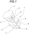
- the embodiment shown of the sealing element for pipes comprises a body (1) of injection-mouldable plastic material, for example, low density polyethylene (LDPE), with a degree of elasticity such that it makes it easier for the operator to assemble the cap since less effort is required to place it in the holes of a tube.
- LDPE low density polyethylene
- the body (1) is made up of an elongated central stem section (2), with a cross-shaped cross-section, which has at one end a circular head region (3) with a flat surface acting as a grip area for the user in the operations of placing and removing the sealing element at one end of the conduit, as well as abutment with the side wall of the tube, once it is assembled.
- the head (3) notably protrudes radially with respect to the central stem section (2).
- the central stem section (2) includes along the same and in a downstream direction from said head region (3) and separately, a first contour centring region (4) with a general inverted frustoconical shape provided to facilitate the fitting and therefore centring of the sealing element inside the conduit to be covered, a second circumferential outer contour region that is defined by two flexible flaps (5), which are formed from a pair of diametrically opposed grooves (6), and a third circumferential outer contour positioning region (7), the second region having a larger diameter than the first and third regions.
- the cross-shaped cross-section comprised between the first and second regions has a decreasing configuration in a downstream direction from the first region towards the second region, as can be seen more clearly in Figures 2 and 3 .
- the central stem section (2) includes at least two spaced extensions (8), which protrude in one same direction perpendicular to the central stem section (2), which have a length equal to or less than the diameter of the third positioning region (7).
- these extensions (8) are parallel to the grooves (6), such that it also allows them to be used as reference or guide points during the insertion action of the sealing element in a corresponding hole.
- the head region can have an outer diameter about 10 mm, the first centring region about 7.4 mm, the outer diameter of the flexible flaps about 10.2 mm, while the third positioning region can have a diameter about 7.4 mm.
Landscapes
- Engineering & Computer Science (AREA)
- General Engineering & Computer Science (AREA)
- Mechanical Engineering (AREA)
- Gasket Seals (AREA)
- Injection Moulding Of Plastics Or The Like (AREA)
- Package Frames And Binding Bands (AREA)
- Buffer Packaging (AREA)
Claims (4)
- Dichtelement für Rohre, umfassend einen Körper (1) aus spritzgießbarem Kunststoff, der aus einem zentralen Schaftabschnitt (2), der an einem Ende einen kreisförmigen Kopfbereich (3) aufweist, der als Griffbereich dient, einschließlich eines an einem Schaftabschnitt in einer Abwärtsrichtung ab dem Kopfbereich (3) befindlichen ersten Zentrierbereichs (4) mit einer allgemein umgekehrt kegelstumpfförmigen Form, eines zweiten umlaufenden Außenkonturbereichs, der durch mindestens zwei flexible Klappen (5) definiert ist, die aus einem Paar diametral gegenüberliegender Nuten (6) gebildet ist, und eines dritten umlaufenden Außenkonturpositionierungsbereichs, wobei der zweite Bereich einen größeren Durchmesser als der erste und der dritte Bereich aufweist, dadurch gekennzeichnet, dass er mindestens zwei voneinander entfernte Verlängerungen (8) umfasst, die in derselben Richtung senkrecht zum zentralen Schaftabschnitt (2) vorstehen, die eine Länge aufweisen, die gleich oder kleiner als der Durchmesser des dritten Positionierungsbereichs ist.
- Dichtelement für Rohre nach Anspruch 1, dadurch gekennzeichnet, dass sich jede der Verlängerungen (8) in einem Bereich nahe den beiden gegenüberliegenden Enden des zentralen Schaftabschnitts (2) befindet.
- Dichtelement für Rohre nach einem der vorhergehenden Ansprüche, dadurch gekennzeichnet, dass der zentrale Schaft (2) einen kreuzförmigen Querschnitt aufweist.
- Dichtelement für Rohre nach den Ansprüchen 1 und 3, dadurch gekennzeichnet, dass der kreuzförmige Querschnitt, der zwischen dem ersten und dem zweiten Bereich in einer Abwärtsrichtung enthalten ist, ab dem ersten Bereich in Richtung des zweiten Bereichs eine abnehmende Konfiguration aufweist.
Applications Claiming Priority (1)
| Application Number | Priority Date | Filing Date | Title |
|---|---|---|---|
| ES202032470U ES1261055Y (es) | 2020-11-17 | 2020-11-17 | Elemento obturador para tuberías |
Publications (3)
| Publication Number | Publication Date |
|---|---|
| EP4001726A1 EP4001726A1 (de) | 2022-05-25 |
| EP4001726B1 true EP4001726B1 (de) | 2023-08-02 |
| EP4001726C0 EP4001726C0 (de) | 2023-08-02 |
Family
ID=74625746
Family Applications (1)
| Application Number | Title | Priority Date | Filing Date |
|---|---|---|---|
| EP21382853.6A Active EP4001726B1 (de) | 2020-11-17 | 2021-09-22 | Dichtelement für rohre |
Country Status (3)
| Country | Link |
|---|---|
| US (1) | US20220154867A1 (de) |
| EP (1) | EP4001726B1 (de) |
| ES (1) | ES1261055Y (de) |
Families Citing this family (3)
| Publication number | Priority date | Publication date | Assignee | Title |
|---|---|---|---|---|
| ES2938573A1 (es) * | 2021-10-07 | 2023-04-12 | Cecotec Res And Development S L | Metodo de aspiracion automatizada por superficies |
| ES1269829Y (es) * | 2021-05-07 | 2021-09-24 | Amo Antonio Brao | Elemento obturador para tuberías |
| ES1287756Y (es) * | 2021-12-16 | 2022-06-01 | Amo Antonio Brao | Elemento obturador para tuberías |
Family Cites Families (16)
| Publication number | Priority date | Publication date | Assignee | Title |
|---|---|---|---|---|
| US1817775A (en) * | 1928-06-20 | 1931-08-04 | Harry E Sipe | Metallic coupling device |
| US3779374A (en) * | 1971-10-20 | 1973-12-18 | Vanguard Industries | Molded plastic fastener |
| JPH10223303A (ja) * | 1997-02-06 | 1998-08-21 | Yazaki Corp | 防水コネクタ用ゴム栓 |
| US5909991A (en) * | 1997-11-24 | 1999-06-08 | Arrow Sign Company | Self adjusting plug |
| USD456880S1 (en) * | 2001-04-11 | 2002-05-07 | Aqueduct Utility Pipe Contractor, Inc. | Plug for apertures |
| US6360779B1 (en) * | 2001-04-11 | 2002-03-26 | Aqueduct Utility Pipe Contractor, Inc. | Closure device for a pipe/wall aperture |
| USD571898S1 (en) * | 2006-05-05 | 2008-06-24 | Gilligan Steven R | Hole cover |
| US20080052878A1 (en) * | 2006-08-31 | 2008-03-06 | Lewis Jeffrey C | Fastener Clip with Seal |
| US20080141574A1 (en) * | 2006-12-15 | 2008-06-19 | Dustin Paul Jones | Color-coded identification plug |
| RO123196B1 (ro) * | 2007-04-06 | 2011-02-28 | Exitehnica S.R.L. | Capac protector, pentru capetele ţevilor netede |
| WO2011119411A1 (en) * | 2010-03-24 | 2011-09-29 | Illinois Tool Works Inc. | Serviceable snap-in fastener |
| DE102011000216A1 (de) * | 2011-01-19 | 2012-07-19 | Stiwa Holding Gmbh | Universelle Verschlussvorrichtung |
| US9216325B2 (en) * | 2013-03-14 | 2015-12-22 | Karsten Manufacturing Corporation | Shaft plugs for golf clubs and methods to manufacture golf clubs |
| US9340338B1 (en) * | 2014-05-16 | 2016-05-17 | Darren Doherty | Water pipe end cap |
| US10640996B2 (en) * | 2015-08-31 | 2020-05-05 | Michael Hartman | Hole cover |
| ES1236244Y (es) * | 2019-09-20 | 2020-01-14 | Amo Antonio Brao | Tapón para tuberías |
-
2020
- 2020-11-17 ES ES202032470U patent/ES1261055Y/es not_active Expired - Fee Related
-
2021
- 2021-09-02 US US17/464,799 patent/US20220154867A1/en not_active Abandoned
- 2021-09-22 EP EP21382853.6A patent/EP4001726B1/de active Active
Also Published As
| Publication number | Publication date |
|---|---|
| EP4001726A1 (de) | 2022-05-25 |
| US20220154867A1 (en) | 2022-05-19 |
| ES1261055U (es) | 2021-02-23 |
| ES1261055Y (es) | 2021-05-14 |
| EP4001726C0 (de) | 2023-08-02 |
Similar Documents
| Publication | Publication Date | Title |
|---|---|---|
| EP4001726B1 (de) | Dichtelement für rohre | |
| US9963862B2 (en) | Elastic membrane strainer for a drain | |
| DE102004032941B4 (de) | Klemmring und Rohrverbindung | |
| DE102005027816B4 (de) | Rohrverbindung | |
| DE112014001591B4 (de) | Staubabdeckung | |
| US20220356979A1 (en) | Sealing element for pipes | |
| US7736107B2 (en) | Clipping device | |
| EP1726865A2 (de) | Verbindungsanordnung mit Endabschnitten zweier zu verbindender Fluidleitungen | |
| EP2350401A2 (de) | Kunststoffablfuss- oder inspektionskammerteil mit hohlwandiger umfangswand sowie formanordnung dafür | |
| US6454308B1 (en) | Telescopic pipe and extendible suction pipe of vacuum cleaner using transparent material | |
| DE4410964A1 (de) | Kunstharzmanschette | |
| IE46130B1 (en) | Teat cup liners | |
| US20100089326A1 (en) | Teatcup liner | |
| RU2737786C2 (ru) | Картридж для доильного стакана и доильный стакан | |
| EP4086498A1 (de) | Dichtelement für rohre | |
| EP1726862A2 (de) | Verbindungsanordnung mit koaxialen Endabschnitten zweier zu verbindender Fluidleitungen | |
| ES1236244U (es) | Tapón para tuberías | |
| EP1356756B1 (de) | Kupplungsmuffe für die Verbindung eines Saugschlauchs mit einem Gehäuse | |
| EP1127224B1 (de) | Kugelgelenk | |
| JP6719318B2 (ja) | セルストレーナー | |
| CN106687346A (zh) | 排液阀 | |
| US20140312047A1 (en) | Water draining plug | |
| US20230194032A1 (en) | Sealing Element for Pipes | |
| KR20220039752A (ko) | 분배 팁 및 그 제조 방법 | |
| GB1564903A (en) | Socket for a stud for footwear |
Legal Events
| Date | Code | Title | Description |
|---|---|---|---|
| PUAI | Public reference made under article 153(3) epc to a published international application that has entered the european phase |
Free format text: ORIGINAL CODE: 0009012 |
|
| STAA | Information on the status of an ep patent application or granted ep patent |
Free format text: STATUS: THE APPLICATION HAS BEEN PUBLISHED |
|
| AK | Designated contracting states |
Kind code of ref document: A1 Designated state(s): AL AT BE BG CH CY CZ DE DK EE ES FI FR GB GR HR HU IE IS IT LI LT LU LV MC MK MT NL NO PL PT RO RS SE SI SK SM TR |
|
| STAA | Information on the status of an ep patent application or granted ep patent |
Free format text: STATUS: REQUEST FOR EXAMINATION WAS MADE |
|
| RBV | Designated contracting states (corrected) |
Designated state(s): AL AT BE BG CH CY CZ DE DK EE ES FI FR GB GR HR HU IE IS IT LI LT LU LV MC MK MT NL NO PL PT RO RS SE SI SK SM TR |
|
| 17P | Request for examination filed |
Effective date: 20220929 |
|
| GRAP | Despatch of communication of intention to grant a patent |
Free format text: ORIGINAL CODE: EPIDOSNIGR1 |
|
| STAA | Information on the status of an ep patent application or granted ep patent |
Free format text: STATUS: GRANT OF PATENT IS INTENDED |
|
| RIC1 | Information provided on ipc code assigned before grant |
Ipc: F16L 57/00 20060101ALI20230222BHEP Ipc: B65D 59/02 20060101ALI20230222BHEP Ipc: F16L 55/11 20060101AFI20230222BHEP |
|
| INTG | Intention to grant announced |
Effective date: 20230317 |
|
| GRAS | Grant fee paid |
Free format text: ORIGINAL CODE: EPIDOSNIGR3 |
|
| GRAA | (expected) grant |
Free format text: ORIGINAL CODE: 0009210 |
|
| STAA | Information on the status of an ep patent application or granted ep patent |
Free format text: STATUS: THE PATENT HAS BEEN GRANTED |
|
| AK | Designated contracting states |
Kind code of ref document: B1 Designated state(s): AL AT BE BG CH CY CZ DE DK EE ES FI FR GB GR HR HU IE IS IT LI LT LU LV MC MK MT NL NO PL PT RO RS SE SI SK SM TR |
|
| REG | Reference to a national code |
Ref country code: GB Ref legal event code: FG4D |
|
| REG | Reference to a national code |
Ref country code: CH Ref legal event code: EP |
|
| REG | Reference to a national code |
Ref country code: DE Ref legal event code: R096 Ref document number: 602021003995 Country of ref document: DE |
|
| REG | Reference to a national code |
Ref country code: IE Ref legal event code: FG4D |
|
| U01 | Request for unitary effect filed |
Effective date: 20230810 |
|
| U07 | Unitary effect registered |
Designated state(s): AT BE BG DE DK EE FI FR IT LT LU LV MT NL PT SE SI Effective date: 20230816 |
|
| U20 | Renewal fee for the european patent with unitary effect paid |
Year of fee payment: 3 Effective date: 20230926 |
|
| PG25 | Lapsed in a contracting state [announced via postgrant information from national office to epo] |
Ref country code: GR Free format text: LAPSE BECAUSE OF FAILURE TO SUBMIT A TRANSLATION OF THE DESCRIPTION OR TO PAY THE FEE WITHIN THE PRESCRIBED TIME-LIMIT Effective date: 20231103 |
|
| PG25 | Lapsed in a contracting state [announced via postgrant information from national office to epo] |
Ref country code: IS Free format text: LAPSE BECAUSE OF FAILURE TO SUBMIT A TRANSLATION OF THE DESCRIPTION OR TO PAY THE FEE WITHIN THE PRESCRIBED TIME-LIMIT Effective date: 20231202 |
|
| PG25 | Lapsed in a contracting state [announced via postgrant information from national office to epo] |
Ref country code: RS Free format text: LAPSE BECAUSE OF FAILURE TO SUBMIT A TRANSLATION OF THE DESCRIPTION OR TO PAY THE FEE WITHIN THE PRESCRIBED TIME-LIMIT Effective date: 20230802 Ref country code: NO Free format text: LAPSE BECAUSE OF FAILURE TO SUBMIT A TRANSLATION OF THE DESCRIPTION OR TO PAY THE FEE WITHIN THE PRESCRIBED TIME-LIMIT Effective date: 20231102 Ref country code: IS Free format text: LAPSE BECAUSE OF FAILURE TO SUBMIT A TRANSLATION OF THE DESCRIPTION OR TO PAY THE FEE WITHIN THE PRESCRIBED TIME-LIMIT Effective date: 20231202 Ref country code: HR Free format text: LAPSE BECAUSE OF FAILURE TO SUBMIT A TRANSLATION OF THE DESCRIPTION OR TO PAY THE FEE WITHIN THE PRESCRIBED TIME-LIMIT Effective date: 20230802 Ref country code: GR Free format text: LAPSE BECAUSE OF FAILURE TO SUBMIT A TRANSLATION OF THE DESCRIPTION OR TO PAY THE FEE WITHIN THE PRESCRIBED TIME-LIMIT Effective date: 20231103 |
|
| PG25 | Lapsed in a contracting state [announced via postgrant information from national office to epo] |
Ref country code: PL Free format text: LAPSE BECAUSE OF FAILURE TO SUBMIT A TRANSLATION OF THE DESCRIPTION OR TO PAY THE FEE WITHIN THE PRESCRIBED TIME-LIMIT Effective date: 20230802 |
|
| PG25 | Lapsed in a contracting state [announced via postgrant information from national office to epo] |
Ref country code: ES Free format text: LAPSE BECAUSE OF FAILURE TO SUBMIT A TRANSLATION OF THE DESCRIPTION OR TO PAY THE FEE WITHIN THE PRESCRIBED TIME-LIMIT Effective date: 20230802 |
|
| PG25 | Lapsed in a contracting state [announced via postgrant information from national office to epo] |
Ref country code: SM Free format text: LAPSE BECAUSE OF FAILURE TO SUBMIT A TRANSLATION OF THE DESCRIPTION OR TO PAY THE FEE WITHIN THE PRESCRIBED TIME-LIMIT Effective date: 20230802 Ref country code: RO Free format text: LAPSE BECAUSE OF FAILURE TO SUBMIT A TRANSLATION OF THE DESCRIPTION OR TO PAY THE FEE WITHIN THE PRESCRIBED TIME-LIMIT Effective date: 20230802 Ref country code: ES Free format text: LAPSE BECAUSE OF FAILURE TO SUBMIT A TRANSLATION OF THE DESCRIPTION OR TO PAY THE FEE WITHIN THE PRESCRIBED TIME-LIMIT Effective date: 20230802 Ref country code: CZ Free format text: LAPSE BECAUSE OF FAILURE TO SUBMIT A TRANSLATION OF THE DESCRIPTION OR TO PAY THE FEE WITHIN THE PRESCRIBED TIME-LIMIT Effective date: 20230802 Ref country code: SK Free format text: LAPSE BECAUSE OF FAILURE TO SUBMIT A TRANSLATION OF THE DESCRIPTION OR TO PAY THE FEE WITHIN THE PRESCRIBED TIME-LIMIT Effective date: 20230802 |
|
| REG | Reference to a national code |
Ref country code: DE Ref legal event code: R097 Ref document number: 602021003995 Country of ref document: DE |
|
| PG25 | Lapsed in a contracting state [announced via postgrant information from national office to epo] |
Ref country code: MC Free format text: LAPSE BECAUSE OF FAILURE TO SUBMIT A TRANSLATION OF THE DESCRIPTION OR TO PAY THE FEE WITHIN THE PRESCRIBED TIME-LIMIT Effective date: 20230802 |
|
| PLBE | No opposition filed within time limit |
Free format text: ORIGINAL CODE: 0009261 |
|
| STAA | Information on the status of an ep patent application or granted ep patent |
Free format text: STATUS: NO OPPOSITION FILED WITHIN TIME LIMIT |
|
| REG | Reference to a national code |
Ref country code: IE Ref legal event code: MM4A |
|
| PG25 | Lapsed in a contracting state [announced via postgrant information from national office to epo] |
Ref country code: IE Free format text: LAPSE BECAUSE OF NON-PAYMENT OF DUE FEES Effective date: 20230922 |
|
| 26N | No opposition filed |
Effective date: 20240503 |
|
| PG25 | Lapsed in a contracting state [announced via postgrant information from national office to epo] |
Ref country code: IE Free format text: LAPSE BECAUSE OF NON-PAYMENT OF DUE FEES Effective date: 20230922 |
|
| REG | Reference to a national code |
Ref country code: CH Ref legal event code: PL |
|
| U90 | Renewal fees not paid: noting of loss of rights |
Free format text: RENEWAL FEE NOT PAID FOR YEAR 04 Effective date: 20250422 |
|
| PG25 | Lapsed in a contracting state [announced via postgrant information from national office to epo] |
Ref country code: CH Free format text: LAPSE BECAUSE OF NON-PAYMENT OF DUE FEES Effective date: 20240930 |
|
| PG25 | Lapsed in a contracting state [announced via postgrant information from national office to epo] |
Ref country code: CY Free format text: LAPSE BECAUSE OF FAILURE TO SUBMIT A TRANSLATION OF THE DESCRIPTION OR TO PAY THE FEE WITHIN THE PRESCRIBED TIME-LIMIT; INVALID AB INITIO Effective date: 20210922 |
|
| U93 | Unitary patent lapsed |
Free format text: RENEWAL FEE NOT PAID Effective date: 20240930 |
|
| PG25 | Lapsed in a contracting state [announced via postgrant information from national office to epo] |
Ref country code: HU Free format text: LAPSE BECAUSE OF FAILURE TO SUBMIT A TRANSLATION OF THE DESCRIPTION OR TO PAY THE FEE WITHIN THE PRESCRIBED TIME-LIMIT; INVALID AB INITIO Effective date: 20210922 |
|
| PG25 | Lapsed in a contracting state [announced via postgrant information from national office to epo] |
Ref country code: TR Free format text: LAPSE BECAUSE OF FAILURE TO SUBMIT A TRANSLATION OF THE DESCRIPTION OR TO PAY THE FEE WITHIN THE PRESCRIBED TIME-LIMIT Effective date: 20230802 |