EP4001736A1 - Wasserdichte lampe - Google Patents
Wasserdichte lampe Download PDFInfo
- Publication number
- EP4001736A1 EP4001736A1 EP21207138.5A EP21207138A EP4001736A1 EP 4001736 A1 EP4001736 A1 EP 4001736A1 EP 21207138 A EP21207138 A EP 21207138A EP 4001736 A1 EP4001736 A1 EP 4001736A1
- Authority
- EP
- European Patent Office
- Prior art keywords
- strip
- baffle
- cover
- cavity
- wires
- Prior art date
- Legal status (The legal status is an assumption and is not a legal conclusion. Google has not performed a legal analysis and makes no representation as to the accuracy of the status listed.)
- Granted
Links
Images



Classifications
-
- F—MECHANICAL ENGINEERING; LIGHTING; HEATING; WEAPONS; BLASTING
- F21—LIGHTING
- F21S—NON-PORTABLE LIGHTING DEVICES; SYSTEMS THEREOF; VEHICLE LIGHTING DEVICES SPECIALLY ADAPTED FOR VEHICLE EXTERIORS
- F21S4/00—Lighting devices or systems using a string or strip of light sources
- F21S4/20—Lighting devices or systems using a string or strip of light sources with light sources held by or within elongate supports
-
- F—MECHANICAL ENGINEERING; LIGHTING; HEATING; WEAPONS; BLASTING
- F21—LIGHTING
- F21V—FUNCTIONAL FEATURES OR DETAILS OF LIGHTING DEVICES OR SYSTEMS THEREOF; STRUCTURAL COMBINATIONS OF LIGHTING DEVICES WITH OTHER ARTICLES, NOT OTHERWISE PROVIDED FOR
- F21V15/00—Protecting lighting devices from damage
- F21V15/01—Housings, e.g. material or assembling of housing parts
- F21V15/015—Devices for covering joints between adjacent lighting devices; End coverings
-
- F—MECHANICAL ENGINEERING; LIGHTING; HEATING; WEAPONS; BLASTING
- F21—LIGHTING
- F21V—FUNCTIONAL FEATURES OR DETAILS OF LIGHTING DEVICES OR SYSTEMS THEREOF; STRUCTURAL COMBINATIONS OF LIGHTING DEVICES WITH OTHER ARTICLES, NOT OTHERWISE PROVIDED FOR
- F21V19/00—Fastening of light sources or lamp holders
- F21V19/001—Fastening of light sources or lamp holders the light sources being semiconductors devices, e.g. LEDs
- F21V19/0015—Fastening arrangements intended to retain light sources
- F21V19/0025—Fastening arrangements intended to retain light sources the fastening means engaging the conductors of the light source, i.e. providing simultaneous fastening of the light sources and their electric connections
-
- F—MECHANICAL ENGINEERING; LIGHTING; HEATING; WEAPONS; BLASTING
- F21—LIGHTING
- F21V—FUNCTIONAL FEATURES OR DETAILS OF LIGHTING DEVICES OR SYSTEMS THEREOF; STRUCTURAL COMBINATIONS OF LIGHTING DEVICES WITH OTHER ARTICLES, NOT OTHERWISE PROVIDED FOR
- F21V27/00—Cable-stowing arrangements structurally associated with lighting devices, e.g. reels
- F21V27/02—Cable inlets
-
- F—MECHANICAL ENGINEERING; LIGHTING; HEATING; WEAPONS; BLASTING
- F21—LIGHTING
- F21V—FUNCTIONAL FEATURES OR DETAILS OF LIGHTING DEVICES OR SYSTEMS THEREOF; STRUCTURAL COMBINATIONS OF LIGHTING DEVICES WITH OTHER ARTICLES, NOT OTHERWISE PROVIDED FOR
- F21V31/00—Gas-tight or water-tight arrangements
- F21V31/04—Provision of filling media
-
- F—MECHANICAL ENGINEERING; LIGHTING; HEATING; WEAPONS; BLASTING
- F21—LIGHTING
- F21V—FUNCTIONAL FEATURES OR DETAILS OF LIGHTING DEVICES OR SYSTEMS THEREOF; STRUCTURAL COMBINATIONS OF LIGHTING DEVICES WITH OTHER ARTICLES, NOT OTHERWISE PROVIDED FOR
- F21V23/00—Arrangement of electric circuit elements in or on lighting devices
- F21V23/001—Arrangement of electric circuit elements in or on lighting devices the elements being electrical wires or cables
- F21V23/002—Arrangements of cables or conductors inside a lighting device, e.g. means for guiding along parts of the housing or in a pivoting arm
-
- F—MECHANICAL ENGINEERING; LIGHTING; HEATING; WEAPONS; BLASTING
- F21—LIGHTING
- F21Y—INDEXING SCHEME ASSOCIATED WITH SUBCLASSES F21K, F21L, F21S and F21V, RELATING TO THE FORM OR THE KIND OF THE LIGHT SOURCES OR OF THE COLOUR OF THE LIGHT EMITTED
- F21Y2103/00—Elongate light sources, e.g. fluorescent tubes
- F21Y2103/10—Elongate light sources, e.g. fluorescent tubes comprising a linear array of point-like light-generating elements
-
- F—MECHANICAL ENGINEERING; LIGHTING; HEATING; WEAPONS; BLASTING
- F21—LIGHTING
- F21Y—INDEXING SCHEME ASSOCIATED WITH SUBCLASSES F21K, F21L, F21S and F21V, RELATING TO THE FORM OR THE KIND OF THE LIGHT SOURCES OR OF THE COLOUR OF THE LIGHT EMITTED
- F21Y2115/00—Light-generating elements of semiconductor light sources
- F21Y2115/10—Light-emitting diodes [LED]
Definitions
- the present invention relates to the technical field of waterproof lamps, and in particular to a waterproof lamp with a wire.
- Lamps and lanterns mainly include lampshade, lamp holder, main board, and end structure seal.
- the end seal structure on the market is divided into two types: waterproof and non-waterproof.
- the wires are divided into tension devices and tension requirements. Waterproofing is generally achieved by filling the space with soft materials to achieve the waterproof effect.
- the present invention provides a waterproof lamp with a wire to solve the above technical problems.
- a waterproof lamp with wires including:
- said baffle cover is provided with a connecting rod on the side facing the inner baffle, and said inner baffle is provided with a connecting hole for mating with said connecting rod.
- said baffle cover is provided with said glue injection holes.
- said baffle cover is manufactured from a transparent material.
- said inner baffle is manufactured from a flexible material, and is in interference fit to said mounting cavity.
- said strip-shaped light body comprises a strip-shaped base and an strip-shaped optical element that are interlocked to form said mounting cavity.
- said strip-shaped optical element is a lampshade.
- said light source assembly comprises a strip-shaped circuit board disposed within said mounting cavity and a light emitting unit disposed with said strip-shaped circuit board facing said strip-shaped optical element.
- said strip-shaped circuit board is provided with pads at the end of said strip-shaped circuit board, said pads being located at or near said mounting opening.
- said strip-shaped circuit board is provided with a fixing hole at one end provided with a pad, and said inner baffle is provided with a post that fits into the fixing hole.
- said side of said baffle cover facing said inner baffle is a flat surface.
- said strip-shaped optical element is shorter at the end than said strip-shaped base, said portion of said baffle cover protruding towards said baffle cover in proximity to said strip-shaped optical element, said gluing cavity being divided into a smaller upper cavity and a larger lower cavity, said wire being located in said lower cavity.
- said end cover assembly further comprises an outer cover provided on the outside of said baffle cover, said outer cover being provided with a second threaded hole for said wire to pass through.
- said outer cover is provided with a protruding plurality of hock elements on the outer side around the second threaded hole, said hock element being distributed around said second threaded hole, at least one hock element being provided with a convex rib on the inner side, said end cover assembly further comprising a locking sleeve that circumferentially locks all the hock element.
- said hock element is provided with two symmetrically arranged hock elements, each hock element having a barb on the outer side, said locking sleeve having a locking hole on the side wall that fits into said barb.
- the waterproof lamp with wires of the present invention is provided with a gluing cavity at the end of the lamp body for gluing and encapsulation by means of an end cover assembly to improve the waterproof level, and the wires of the external plug connector are glued and encapsulated in said lamp body, and the end of the outer sheath covering of the wires is encapsulated in the gluing cavity to prevent water from entering the lamp body between the outer sheath covering of said external plug connector and the inner wires to further improve the waterproof reliability.
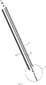
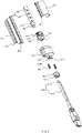
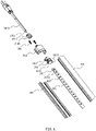
- the waterproof lamp with wires of this embodiment includes a strip-shaped lamp body 100, a light source assembly 200 and an end cover assembly 300.
- the strip-shaped lamp body 100 is provided with a mounting cavity 101 extending along its length and having a mounting opening 102 at an end; the light source assembly 200 is provided in said mounting cavity 101; the end cover assembly 300 is used to encapsulate said mounting opening 102.
- Said mounting opening 102 may be provided at only one end of said mounting cavity 101 or both ends, in this embodiment, both ends are provided with a mounting opening 102, one end of which does not need to be connected to electricity and therefore can be sealed using a prior art waterproof end cover, while the end of the other end of the mounting opening 102 needs to be sealed by an end cover assembly 300, in this embodiment, said end cover assembly 300 includes an inner baffle 301, a baffle cover 302, and an external plug 303.
- the inner baffle 301 is provided in said mounting cavity 101 near said mounting opening 102 for blocking glue, so that neutral silicone will not spill into the interior of the lamp body during production, improving production efficiency; further, said inner baffle 301 is made of a flexible material, and is overfitted with said mounting cavity 101, and the overfitting can improve the effect of blocking glue.
- Baffle cover 302 is provided at the end of said strip-shaped light body 100 for encapsulating said mounting opening 102, and the cover is provided with a first threaded hole 3021, and a gluing cavity 400 is formed between said baffle cover 302 and inner baffle 301, and said gluing cavity 400 is provided with a glue filling hole 401; during manufacture, neutral glue is filled in through the glue filling hole, and neutral glue flows out from the gap between baffle cover 302 and mounting opening 102 and from the first threaded hole 3021, which indicates that the glue injection is complete. Further, said baffle cover 302 is manufactured from a transparent material so that the extent of glue filling can be seen, allowing the glue filling process to be controlled and preventing overfilling or not filling.
- said baffle 302 is provided with a connection bar 3022 on the side facing the inner baffle 301, and said inner baffle 301 is provided with a connection hole 3012 that fits with said connection bar 3022.
- said baffle cover 302 is provided with said glue injection hole 401 for the convenience of glue injection; alternatively, the glue injection hole 401 may also be provided in said strip-shaped light body 100.
- the external plug 303 has a wire 3031 that passes through said first threaded hole 3021 into said mounting cavity 101 and is electrically connected to said light source assembly 300, said wire 3031 comprising a plurality of inner wires 3033 and an outer sheath 3034 that covers all of the inner wires 3033, the end of said outer sheath 3034 being located in said glue injection cavity 400.
- the end of the outer sheathing covering 3034 is not sealed, water will seep into the lamp body between the outer sheathing covering of the wires and the inner wires due to the pressure difference between the inside and outside of the lamp, and the above structure avoids this problem while accomplishing an effective seal of the mounting opening 102.
- said strip-shaped light body 100 includes a strip-shaped base 103 and a strip-shaped optical element 104 which are docked to each other to form said mounting cavity 101.
- said strip-shaped optical element 104 Shaped with a slot 1031 on both sides, said strip-shaped optical element 104 extending downwardly on both sides to form a card edge 1041, said card edge 1041 inserted into the slot 1031 to achieve a connection, before the connection the strip-shaped base 103 is dotted with neutral silicone, the strip-shaped optical element 104 is connected to the strip-shaped base 103, and The gap filling is to achieve the waterproof effect in the circumferential direction of the installation cavity 101 .
- the strip-shaped optical element 104 is used to distribute the light of the light source, and may be a lens or an ordinary lampshade, and the lampshade may incorporate diffusion powder to make the light output more uniform, and in this embodiment, said strip-shaped optical element 104 is a lampshade with an arched cross-section.
- Said light source assembly 200 may be a variety of devices that emit light via electricity, and for ease of manufacture and installation, said light source assembly 200 in this embodiment comprises a strip-shaped circuit board 201 provided within said mounting cavity 101 and a light emitting unit 202 provided within said strip-shaped circuit board 201 toward said strip-shaped optical element 104. Further, said light emitting unit 202 is an LED chip. Said strip-shaped base 103 is provided with a mounting slot 1032 penetrating said strip-shaped circuit board 201.
- Said external plug 303 is electrically connected to the strip-shaped circuit board 201 in many ways, either by plugging or by soldering, in this embodiment, said strip-shaped circuit board 201 is provided with pads 2011 at the end of said strip-shaped circuit board 201, said pads 2011 being located at or near said mounting opening 102.
- Said external plug 303 is electrically connected by soldering the inner wires 3033, generally, the inner wires 3033 are provided with two positive and negative terminals, correspondingly, there are also two pads 2011 are also provided.
- said strip-shaped circuit board 201 is provided with a fixing hole 2012 at one end of the pad 2011, and said inner baffle 301 is provided with a tab 3011 that fits into this fixing hole 2012. Said strip-shaped circuit board 201 and inner baffle 301 are connected to achieve fixation.
- said baffle cover 302 needs to be matched to the mounting opening 102. As shown in FIG. 7 , in an alternative embodiment, said baffle cover 302 is flush on the side facing said inner baffle 301. If said strip-shaped optical element 104 is flush with said strip-shaped base 103 at the end, at that point said baffle cover 302 may be located on the outside of the end. If said strip-shaped optical element 104 is shorter at the end than said strip-shaped base 103, the mounting opening 102 forms a step, at which point the baffle cover 302 may be mounted flush with said strip-shaped optical element 104 at the end within the strip-shaped base 103.
- said strip-shaped optical element 104 is shorter at the end than said strip-shaped base 103, said portion of said baffle cover 302 near said strip-shaped optical element 104 protrudes in the direction of said baffle cover 302, said glue injection cavity 400 is divided into a smaller upper cavity 402 and a larger lower cavity 403, said wire 3031 is located in said lower cavity 403, and wire 3031 is provided in the lower cavity 403.
- the above structure allows for complete encapsulation of the wire 3031 while reducing the amount of glue.
- said end cover assembly 300 further comprises an outer cover 304 provided on the outside of said baffle cover 302, said outer cover 304 being provided with a second threaded hole 3041 for said wire 3031 to pass through. Since there will be adhesive spillage between the baffle cover 302 and said mounting opening 102, the outer cover 304 is added to wrap around the baffle cover 302 for aesthetic considerations. The outer cover 304 is secured by screws 305 to said strip-shaped light body 100, while pressing to secure said baffle cover 302.
- the outer side of said outer cover 304 is provided with a protruding plurality of hock elements 3042 around the second threaded hole 3041, said hock element 3042 is distributed around said second threaded hole 3041, at least one hock element 3042 is provided with a convex rib 3043 on the inner side, and said end cover assembly 300 further comprises a locking sleeve 3045 that circumferentially locks all hock element 3042.
- the above structure in the second threaded hole 3041 is positioned to compress the wire 3031 to achieve a wire pull-proof effect, which is efficient and convenient in terms of production efficiency.
- the lock sleeve 3045 is also secured in many ways, and in this embodiment, said hock element 3042 is provided with two symmetrically arranged hock elements, each hock element 3042 having a barb 3046 on the outer side, and said lock sleeve 3045 is provided with a lock hole 3047 in the side wall that fits with said barb 3046.
Landscapes
- Engineering & Computer Science (AREA)
- General Engineering & Computer Science (AREA)
- Arrangement Of Elements, Cooling, Sealing, Or The Like Of Lighting Devices (AREA)
- Non-Portable Lighting Devices Or Systems Thereof (AREA)
Applications Claiming Priority (1)
| Application Number | Priority Date | Filing Date | Title |
|---|---|---|---|
| CN202011265825.8A CN112728442A (zh) | 2020-11-13 | 2020-11-13 | 一种带导线的防水灯具 |
Publications (2)
| Publication Number | Publication Date |
|---|---|
| EP4001736A1 true EP4001736A1 (de) | 2022-05-25 |
| EP4001736B1 EP4001736B1 (de) | 2025-07-30 |
Family
ID=75597548
Family Applications (1)
| Application Number | Title | Priority Date | Filing Date |
|---|---|---|---|
| EP21207138.5A Active EP4001736B1 (de) | 2020-11-13 | 2021-11-09 | Wasserdichte lampe |
Country Status (2)
| Country | Link |
|---|---|
| EP (1) | EP4001736B1 (de) |
| CN (1) | CN112728442A (de) |
Cited By (1)
| Publication number | Priority date | Publication date | Assignee | Title |
|---|---|---|---|---|
| CN116221687A (zh) * | 2022-12-27 | 2023-06-06 | 广州市莱帝亚照明股份有限公司 | 一种灯带及其安装方法 |
Citations (5)
| Publication number | Priority date | Publication date | Assignee | Title |
|---|---|---|---|---|
| CN203771142U (zh) * | 2014-03-31 | 2014-08-13 | 赐建科技股份有限公司 | Led灯具封装装置 |
| EP2960576A1 (de) * | 2014-06-25 | 2015-12-30 | Lin, Wanjiong | Led-lampe mit wasserdichter struktur |
| CN110043812A (zh) * | 2019-04-28 | 2019-07-23 | 赛尔富电子有限公司 | 一种互联灯具 |
| US20190368720A1 (en) * | 2018-05-31 | 2019-12-05 | Wanjiong Lin | LED Lamp |
| CN111853572A (zh) * | 2020-07-02 | 2020-10-30 | 赛尔富电子有限公司 | 一种防水条形灯 |
Family Cites Families (8)
| Publication number | Priority date | Publication date | Assignee | Title |
|---|---|---|---|---|
| KR200359019Y1 (ko) * | 2004-05-07 | 2004-08-21 | 만 석 김 | 방수성 전구 소켓 |
| TWM459371U (zh) * | 2013-02-20 | 2013-08-11 | Fortop Ind Co Ltd | 燈泡座 |
| CN203907486U (zh) * | 2014-05-27 | 2014-10-29 | 宁波港普光电科技有限公司 | 恒压迷你小射灯 |
| CN105226172B (zh) * | 2015-09-08 | 2017-07-14 | 李峰 | 防水封装结构及其一体成型处理工艺 |
| CN207049883U (zh) * | 2017-08-04 | 2018-02-27 | 浙江点金照明有限公司 | 三防灯端盖 |
| CN207500857U (zh) * | 2017-10-31 | 2018-06-15 | 浙江尧亮照明工程有限公司 | 灯具防水结构 |
| CN110686220A (zh) * | 2018-07-05 | 2020-01-14 | 东莞市铭皓照明有限公司 | 一种应用于灯带的快速拆装防拉接线盒 |
| CN214580582U (zh) * | 2020-11-13 | 2021-11-02 | 赛尔富电子有限公司 | 一种带外接导线的防水灯具 |
-
2020
- 2020-11-13 CN CN202011265825.8A patent/CN112728442A/zh active Pending
-
2021
- 2021-11-09 EP EP21207138.5A patent/EP4001736B1/de active Active
Patent Citations (5)
| Publication number | Priority date | Publication date | Assignee | Title |
|---|---|---|---|---|
| CN203771142U (zh) * | 2014-03-31 | 2014-08-13 | 赐建科技股份有限公司 | Led灯具封装装置 |
| EP2960576A1 (de) * | 2014-06-25 | 2015-12-30 | Lin, Wanjiong | Led-lampe mit wasserdichter struktur |
| US20190368720A1 (en) * | 2018-05-31 | 2019-12-05 | Wanjiong Lin | LED Lamp |
| CN110043812A (zh) * | 2019-04-28 | 2019-07-23 | 赛尔富电子有限公司 | 一种互联灯具 |
| CN111853572A (zh) * | 2020-07-02 | 2020-10-30 | 赛尔富电子有限公司 | 一种防水条形灯 |
Cited By (1)
| Publication number | Priority date | Publication date | Assignee | Title |
|---|---|---|---|---|
| CN116221687A (zh) * | 2022-12-27 | 2023-06-06 | 广州市莱帝亚照明股份有限公司 | 一种灯带及其安装方法 |
Also Published As
| Publication number | Publication date |
|---|---|
| CN112728442A (zh) | 2021-04-30 |
| EP4001736B1 (de) | 2025-07-30 |
Similar Documents
| Publication | Publication Date | Title |
|---|---|---|
| US10134939B2 (en) | Optical sensor module and a wearable device including the same | |
| CN100431180C (zh) | 发射和/或接收电磁辐射的半导体元器件 | |
| KR100904152B1 (ko) | 히트싱크 지지부를 갖는 리드프레임, 그것을 사용한 발광다이오드 패키지 제조방법 및 그것에 의해 제조된 발광다이오드 패키지 | |
| US8132955B2 (en) | Lamp body used in the LED light string | |
| US10914428B2 (en) | LED light apparatus | |
| KR20090044306A (ko) | 발광다이오드 패키지 | |
| CN110043812A (zh) | 一种互联灯具 | |
| EP4001736B1 (de) | Wasserdichte lampe | |
| CN214580582U (zh) | 一种带外接导线的防水灯具 | |
| KR101367381B1 (ko) | Led 패키지 | |
| JP2007242711A (ja) | Led発光装置 | |
| CN221466601U (zh) | Led封装结构和发光设备 | |
| CN217981943U (zh) | 一种发射端组件及光电耦合装置 | |
| JP6660580B2 (ja) | 照明器具 | |
| CN109611706A (zh) | 一种led照明灯具 | |
| KR20120004162U (ko) | 엘이디 조명 | |
| CN212537622U (zh) | Led灯具 | |
| CA2592671A1 (en) | Light-bulb conductive device | |
| CN223859586U (zh) | 一种led模块的端部封装结构以及具备端部封装结构的led模块 | |
| CN215731677U (zh) | 一种防溢锡贴片式二极管 | |
| CN220771076U (zh) | 一种防水led灯 | |
| CN223297994U (zh) | 一种显示rgb-led灯珠结构 | |
| CN218039956U (zh) | 插座电连接器 | |
| CN218763287U (zh) | 一种填胶密封式防水led灯泡 | |
| CN116154080B (zh) | Led封装结构和发光设备 |
Legal Events
| Date | Code | Title | Description |
|---|---|---|---|
| PUAI | Public reference made under article 153(3) epc to a published international application that has entered the european phase |
Free format text: ORIGINAL CODE: 0009012 |
|
| STAA | Information on the status of an ep patent application or granted ep patent |
Free format text: STATUS: THE APPLICATION HAS BEEN PUBLISHED |
|
| AK | Designated contracting states |
Kind code of ref document: A1 Designated state(s): AL AT BE BG CH CY CZ DE DK EE ES FI FR GB GR HR HU IE IS IT LI LT LU LV MC MK MT NL NO PL PT RO RS SE SI SK SM TR |
|
| STAA | Information on the status of an ep patent application or granted ep patent |
Free format text: STATUS: REQUEST FOR EXAMINATION WAS MADE |
|
| 17P | Request for examination filed |
Effective date: 20221125 |
|
| RBV | Designated contracting states (corrected) |
Designated state(s): AL AT BE BG CH CY CZ DE DK EE ES FI FR GB GR HR HU IE IS IT LI LT LU LV MC MK MT NL NO PL PT RO RS SE SI SK SM TR |
|
| STAA | Information on the status of an ep patent application or granted ep patent |
Free format text: STATUS: EXAMINATION IS IN PROGRESS |
|
| 17Q | First examination report despatched |
Effective date: 20240909 |
|
| GRAP | Despatch of communication of intention to grant a patent |
Free format text: ORIGINAL CODE: EPIDOSNIGR1 |
|
| STAA | Information on the status of an ep patent application or granted ep patent |
Free format text: STATUS: GRANT OF PATENT IS INTENDED |
|
| INTG | Intention to grant announced |
Effective date: 20250225 |
|
| RIC1 | Information provided on ipc code assigned before grant |
Ipc: F21Y 103/10 20160101ALN20250214BHEP Ipc: F21Y 115/10 20160101ALN20250214BHEP Ipc: F21V 31/04 20060101ALI20250214BHEP Ipc: F21V 27/02 20060101ALI20250214BHEP Ipc: F21V 15/015 20060101ALI20250214BHEP Ipc: F21S 4/20 20160101AFI20250214BHEP |
|
| GRAS | Grant fee paid |
Free format text: ORIGINAL CODE: EPIDOSNIGR3 |
|
| GRAA | (expected) grant |
Free format text: ORIGINAL CODE: 0009210 |
|
| STAA | Information on the status of an ep patent application or granted ep patent |
Free format text: STATUS: THE PATENT HAS BEEN GRANTED |
|
| AK | Designated contracting states |
Kind code of ref document: B1 Designated state(s): AL AT BE BG CH CY CZ DE DK EE ES FI FR GB GR HR HU IE IS IT LI LT LU LV MC MK MT NL NO PL PT RO RS SE SI SK SM TR |
|
| REG | Reference to a national code |
Ref country code: GB Ref legal event code: FG4D |
|
| REG | Reference to a national code |
Ref country code: CH Ref legal event code: EP |
|
| REG | Reference to a national code |
Ref country code: DE Ref legal event code: R096 Ref document number: 602021034994 Country of ref document: DE |
|
| REG | Reference to a national code |
Ref country code: IE Ref legal event code: FG4D |
|
| REG | Reference to a national code |
Ref country code: NL Ref legal event code: MP Effective date: 20250730 |
|
| REG | Reference to a national code |
Ref country code: AT Ref legal event code: MK05 Ref document number: 1819270 Country of ref document: AT Kind code of ref document: T Effective date: 20250730 |
|
| PG25 | Lapsed in a contracting state [announced via postgrant information from national office to epo] |
Ref country code: PT Free format text: LAPSE BECAUSE OF FAILURE TO SUBMIT A TRANSLATION OF THE DESCRIPTION OR TO PAY THE FEE WITHIN THE PRESCRIBED TIME-LIMIT Effective date: 20251202 |
|
| PG25 | Lapsed in a contracting state [announced via postgrant information from national office to epo] |
Ref country code: IS Free format text: LAPSE BECAUSE OF FAILURE TO SUBMIT A TRANSLATION OF THE DESCRIPTION OR TO PAY THE FEE WITHIN THE PRESCRIBED TIME-LIMIT Effective date: 20251130 |
|
| PGFP | Annual fee paid to national office [announced via postgrant information from national office to epo] |
Ref country code: DE Payment date: 20251128 Year of fee payment: 5 |
|
| PG25 | Lapsed in a contracting state [announced via postgrant information from national office to epo] |
Ref country code: NO Free format text: LAPSE BECAUSE OF FAILURE TO SUBMIT A TRANSLATION OF THE DESCRIPTION OR TO PAY THE FEE WITHIN THE PRESCRIBED TIME-LIMIT Effective date: 20251030 |
|
| REG | Reference to a national code |
Ref country code: LT Ref legal event code: MG9D |
|
| PG25 | Lapsed in a contracting state [announced via postgrant information from national office to epo] |
Ref country code: AT Free format text: LAPSE BECAUSE OF FAILURE TO SUBMIT A TRANSLATION OF THE DESCRIPTION OR TO PAY THE FEE WITHIN THE PRESCRIBED TIME-LIMIT Effective date: 20250730 |
|
| PG25 | Lapsed in a contracting state [announced via postgrant information from national office to epo] |
Ref country code: FI Free format text: LAPSE BECAUSE OF FAILURE TO SUBMIT A TRANSLATION OF THE DESCRIPTION OR TO PAY THE FEE WITHIN THE PRESCRIBED TIME-LIMIT Effective date: 20250730 |
|
| PG25 | Lapsed in a contracting state [announced via postgrant information from national office to epo] |
Ref country code: NL Free format text: LAPSE BECAUSE OF FAILURE TO SUBMIT A TRANSLATION OF THE DESCRIPTION OR TO PAY THE FEE WITHIN THE PRESCRIBED TIME-LIMIT Effective date: 20250730 Ref country code: HR Free format text: LAPSE BECAUSE OF FAILURE TO SUBMIT A TRANSLATION OF THE DESCRIPTION OR TO PAY THE FEE WITHIN THE PRESCRIBED TIME-LIMIT Effective date: 20250730 |
|
| PG25 | Lapsed in a contracting state [announced via postgrant information from national office to epo] |
Ref country code: GR Free format text: LAPSE BECAUSE OF FAILURE TO SUBMIT A TRANSLATION OF THE DESCRIPTION OR TO PAY THE FEE WITHIN THE PRESCRIBED TIME-LIMIT Effective date: 20251031 |
|
| PG25 | Lapsed in a contracting state [announced via postgrant information from national office to epo] |
Ref country code: SE Free format text: LAPSE BECAUSE OF FAILURE TO SUBMIT A TRANSLATION OF THE DESCRIPTION OR TO PAY THE FEE WITHIN THE PRESCRIBED TIME-LIMIT Effective date: 20250730 |
|
| PG25 | Lapsed in a contracting state [announced via postgrant information from national office to epo] |
Ref country code: LV Free format text: LAPSE BECAUSE OF FAILURE TO SUBMIT A TRANSLATION OF THE DESCRIPTION OR TO PAY THE FEE WITHIN THE PRESCRIBED TIME-LIMIT Effective date: 20250730 |
|
| PG25 | Lapsed in a contracting state [announced via postgrant information from national office to epo] |
Ref country code: BG Free format text: LAPSE BECAUSE OF FAILURE TO SUBMIT A TRANSLATION OF THE DESCRIPTION OR TO PAY THE FEE WITHIN THE PRESCRIBED TIME-LIMIT Effective date: 20250730 Ref country code: PL Free format text: LAPSE BECAUSE OF FAILURE TO SUBMIT A TRANSLATION OF THE DESCRIPTION OR TO PAY THE FEE WITHIN THE PRESCRIBED TIME-LIMIT Effective date: 20250730 |
|
| PG25 | Lapsed in a contracting state [announced via postgrant information from national office to epo] |
Ref country code: RS Free format text: LAPSE BECAUSE OF FAILURE TO SUBMIT A TRANSLATION OF THE DESCRIPTION OR TO PAY THE FEE WITHIN THE PRESCRIBED TIME-LIMIT Effective date: 20251030 |
|
| PG25 | Lapsed in a contracting state [announced via postgrant information from national office to epo] |
Ref country code: ES Free format text: LAPSE BECAUSE OF FAILURE TO SUBMIT A TRANSLATION OF THE DESCRIPTION OR TO PAY THE FEE WITHIN THE PRESCRIBED TIME-LIMIT Effective date: 20250730 |
|
| PG25 | Lapsed in a contracting state [announced via postgrant information from national office to epo] |
Ref country code: RO Free format text: LAPSE BECAUSE OF FAILURE TO SUBMIT A TRANSLATION OF THE DESCRIPTION OR TO PAY THE FEE WITHIN THE PRESCRIBED TIME-LIMIT Effective date: 20250730 |
|
| PG25 | Lapsed in a contracting state [announced via postgrant information from national office to epo] |
Ref country code: SM Free format text: LAPSE BECAUSE OF FAILURE TO SUBMIT A TRANSLATION OF THE DESCRIPTION OR TO PAY THE FEE WITHIN THE PRESCRIBED TIME-LIMIT Effective date: 20250730 |
|
| PG25 | Lapsed in a contracting state [announced via postgrant information from national office to epo] |
Ref country code: DK Free format text: LAPSE BECAUSE OF FAILURE TO SUBMIT A TRANSLATION OF THE DESCRIPTION OR TO PAY THE FEE WITHIN THE PRESCRIBED TIME-LIMIT Effective date: 20250730 |
|
| PG25 | Lapsed in a contracting state [announced via postgrant information from national office to epo] |
Ref country code: IT Free format text: LAPSE BECAUSE OF FAILURE TO SUBMIT A TRANSLATION OF THE DESCRIPTION OR TO PAY THE FEE WITHIN THE PRESCRIBED TIME-LIMIT Effective date: 20250730 |
|
| PG25 | Lapsed in a contracting state [announced via postgrant information from national office to epo] |
Ref country code: CZ Free format text: LAPSE BECAUSE OF FAILURE TO SUBMIT A TRANSLATION OF THE DESCRIPTION OR TO PAY THE FEE WITHIN THE PRESCRIBED TIME-LIMIT Effective date: 20250730 |
|
| PG25 | Lapsed in a contracting state [announced via postgrant information from national office to epo] |
Ref country code: SK Free format text: LAPSE BECAUSE OF FAILURE TO SUBMIT A TRANSLATION OF THE DESCRIPTION OR TO PAY THE FEE WITHIN THE PRESCRIBED TIME-LIMIT Effective date: 20250730 Ref country code: EE Free format text: LAPSE BECAUSE OF FAILURE TO SUBMIT A TRANSLATION OF THE DESCRIPTION OR TO PAY THE FEE WITHIN THE PRESCRIBED TIME-LIMIT Effective date: 20250730 |