EP4001751A1 - Luminaire d'éclairage public à capteur d'humidité intégré - Google Patents
Luminaire d'éclairage public à capteur d'humidité intégré Download PDFInfo
- Publication number
- EP4001751A1 EP4001751A1 EP21207810.9A EP21207810A EP4001751A1 EP 4001751 A1 EP4001751 A1 EP 4001751A1 EP 21207810 A EP21207810 A EP 21207810A EP 4001751 A1 EP4001751 A1 EP 4001751A1
- Authority
- EP
- European Patent Office
- Prior art keywords
- light
- street light
- cover
- sensor
- electrode
- Prior art date
- Legal status (The legal status is an assumption and is not a legal conclusion. Google has not performed a legal analysis and makes no representation as to the accuracy of the status listed.)
- Pending
Links
Images


Classifications
-
- F—MECHANICAL ENGINEERING; LIGHTING; HEATING; WEAPONS; BLASTING
- F21—LIGHTING
- F21V—FUNCTIONAL FEATURES OR DETAILS OF LIGHTING DEVICES OR SYSTEMS THEREOF; STRUCTURAL COMBINATIONS OF LIGHTING DEVICES WITH OTHER ARTICLES, NOT OTHERWISE PROVIDED FOR
- F21V23/00—Arrangement of electric circuit elements in or on lighting devices
- F21V23/04—Arrangement of electric circuit elements in or on lighting devices the elements being switches
- F21V23/0442—Arrangement of electric circuit elements in or on lighting devices the elements being switches activated by means of a sensor, e.g. motion or photodetectors
-
- F—MECHANICAL ENGINEERING; LIGHTING; HEATING; WEAPONS; BLASTING
- F21—LIGHTING
- F21W—INDEXING SCHEME ASSOCIATED WITH SUBCLASSES F21K, F21L, F21S and F21V, RELATING TO USES OR APPLICATIONS OF LIGHTING DEVICES OR SYSTEMS
- F21W2131/00—Use or application of lighting devices or systems not provided for in codes F21W2102/00-F21W2121/00
- F21W2131/10—Outdoor lighting
- F21W2131/103—Outdoor lighting of streets or roads
Definitions
- the present invention relates to a street lamp which is set up to change the light output depending on the weather.
- the weather has a strong influence on visibility in road traffic.
- the requirements for the lighting task change with fog, rain or snow.
- the lighting which is perceived as ideal when it is dry and when visibility is good, can lead to strong scattering or glare in precipitation and fog, which is perceived as unpleasant, tiring or tiring for road users. This can also lead to impairment of road safety.
- Such systems for detecting fog are e.g. LiDAR or IR sensors, which provide information about the particle density or the amount of rain in the air via the reflection curves of the emitted light.
- sensors are known which directly detect the wetness of the road.
- the sensor systems mentioned are complex and are therefore provided outside the lamp for controlling preferably a plurality of lamps.
- Object of the present invention is to provide a street light, which in the simplest possible way can provide weather-dependent light output without great design effort.
- the object is achieved by a street light according to claim 1.
- a special feature of the street light of the present invention is that a moisture sensor is integrated directly into the light.
- the moisture sensor can be designed in various ways, with capacitive systems, which are structurally very simple, being particularly preferred.
- sensors can also be used which are based, for example, on a sound measurement or an optical principle.
- the moisture sensors are accommodated in the street light itself, namely under a light cover, e.g. a transparent light cover, or under a housing component of the light.
- the humidity sensors are therefore completely concealed and not directly exposed to the weather environment.
- the structurally simple sensors have the advantage that inside the lights they are simply connected to a control unit in the light itself and the control unit can change the light emission according to the measured humidity.
- a connection to an external measuring device is not necessary.
- the lamp can be sealed with the integrated moisture sensor in the same way as with conventional lamps.
- the street light has a moisture sensor which is set up to measure a change in capacitance, the capacitance being measured between two electrodes and a first of the electrodes being integrated in the housing component or one of the electrodes is formed by the housing component itself, which in this case is metallic.
- the capacitance measured between the two electrodes changes with humidity because the dielectric constant of water or snow is much higher than the dielectric constant of air. Therefore, if there are raindrops or snow in the area of the electrodes, for example on the outside of the housing, the capacitance changes because the capacitance between electrodes depends on the dielectric surrounding the electrodes.
- This construction is very simple because at least one of the electrodes can be integrated into the housing or can be formed by the housing itself. It is also not a problem if, according to one embodiment, the housing is provided with an insulating lacquer on the outside. The film of moisture on the outside over the insulation also causes the change in capacitance, which is sufficient to detect the moisture.
- a counter-electrode of the first electrode is attached to an inside of the housing component, electrically insulated from the first electrode, or is integrated in the housing component or in the lamp cover, electrically insulated from the first electrode.
- the moisture sensor has a plurality of first electrodes, which are integrated in an insulating body of the lamp cover, and a counter-electrode, which is attached to or behind the lamp cover in an electrically insulated manner.
- the plurality of first electrodes can be arranged next to one another in strips, for example, and the counter-electrode by a ring-shaped Arrangement may be formed around the first electrodes. This structure ensures that when there is moisture on the sensor, the capacitance between the first electrode and the counter-electrode changes more than in the case of a structure with only two electrodes. This makes the measurement more sensitive.
- a plurality of first electrodes are arranged in an insulating body of the street light and a counter-electrode is formed by the housing component, which is metallic.
- the housing component which is metallic.
- the humidity sensor is based on an optical measuring principle and the humidity sensor is fitted behind a light cover that is transparent.
- the lamp cover can, for example, be the same transparent lamp cover that is already present as the light exit surface of the street lamp. Because the optical sensor is installed behind the cover, it is also fully integrated into the luminaire.
- the humidity sensor is set up to emit a light pulse from a transmitter, which passes through the transparent lamp cover and, in the case of a drop of water on the outside of the transparent lamp cover, is scattered back by this to a receiver of the humidity sensor through the transparent cover.
- This measuring principle is very precise and even makes it possible to distinguish different types of precipitation such as rain or snow, since the back reflection of the size and type of water droplets resting on the transparent cover.
- the transparent cover is designed at least partially as a lens. This embodiment makes it possible to further increase the measurement sensitivity, because the light beam reflected by a water drop can be bundled onto a sensor element inside the lamp through the lens.
- the light emitted by the moisture sensor is in the infrared range.
- Light in the infrared range can be easily detected electronically and also has the advantage that interference, such as extraneous light hitting the sensor from a vehicle headlight, does not affect the measurement result.
- the moisture sensor comprises a radar sensor module, in particular a Doppler radar sensor module, a vibration sensor, a piezo sound pickup or a microphone, wherein the moisture sensor is attached to an inside of the lamp cover or the housing component and is set up to detect sound waves which caused by raindrops hitting the lamp cover or housing.
- the raindrops hitting the luminaire cover or housing generate sound waves that are characteristic of the intensity of the precipitation. The detection of the sound waves therefore even allows a rain intensity to be detected quantitatively.
- the moisture sensor includes a radio frequency identification, RFID, antenna on an inside of the light cover attached and arranged to measure an impedance change.
- RFID radio frequency identification
- This embodiment is particularly easy to implement since the RFID antenna for measuring an impedance change does not make any special demands on the exact positioning.
- This embodiment is preferred for non-metallic lamp covers or housings.
- the street lamp also has a temperature gauge, wherein the control device further changes the light output more sharply when the temperature gauge indicates a temperature below freezing point.
- the temperature meter serves to further interpret the measurement results of the humidity sensor, in particular to distinguish between rain and snow. Even if the humidity sensor is designed to distinguish a rain-soaked surface from a snow-covered surface, this measurement is falsified by the fact that a snow cover is melted again relatively quickly due to the heat generated by the lamp. However, a separate temperature sensor can be used to conclude that there is still snow cover at least on surfaces outside of the light, while only a rain-wet surface is detected on the light itself at the moisture sensor.
- the results of the temperature measurement are processed by the light's control unit to change the light output in addition to the measurement results of the humidity sensor.
- the invention relates to a street lamp with an integrated moisture sensor. Only a section of the street light is shown in each of the figures which the humidity sensor is integrated.
- the capacitive measuring method includes an electronic circuit for measuring the capacitance between at least two electrodes.
- the at least two electrodes are electrically connected to a measuring system in the lamp.
- Moisture such as fog, dew, rain or snow changes the dielectric constant of the material in the area of the electrodes, which changes the capacitance.
- the amount of change in capacitance provides information about the amount of moisture. Contamination also has a direct impact on capacity. Therefore, in the embodiments, not the absolute capacitances but only the relative changes in capacitance are measured. This means that the influence of dirt, which has a permanent effect on the luminaire, can be suppressed.
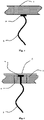
- FIG 1 an embodiment is shown in which an electrode 2 is mounted on the inside of a housing portion 1 of the lamp.
- the electrode 2 is connected to the measuring system via a measuring line 3 via a bleeder resistor.
- the measuring line to the housing section 1, which serves as the second electrode in this embodiment, is not shown.
- the figure 2 shows an alternative embodiment in which the electrode 2 is integrated into the housing section 1 with an insulating body 4 . Furthermore, an insulating coating 5 is provided on the housing section and the measuring electrode 2 as protection against contact with the outside. As in the embodiment after figure 1 In this case, the housing 1 serves as a counter-electrode for the measuring electrode 2.
- the figure 3 shows a further embodiment in which a measuring electrode 2 is similar to that in figure 2 is arranged in an insulating body 4 and under a contact protection 5 in a section of the housing 5 .
- the counter-electrode is not formed by the housing itself, but by a separate electrode 6 which is arranged in the insulating body 4 at a distance from the first measuring electrode 2 . Both electrodes 2 and 6 are therefore separated from one another and from the lamp cover 1 via the insulating body 4 .
- the figure 4 shows a variant of the moisture sensor with a plurality of first electrodes 2a-2d and a counter-electrode 6, which surrounds the plurality of first electrodes 2a-2d arranged in strips.
- the electrodes 2a-2d are separated from each other and from the counter-electrode 6 by an insulating body 4.
- FIG. The entire arrangement is arranged in a section of the lamp housing 1 . Due to the larger number of separate measuring electrodes, a more precise moisture measurement can be achieved.
- a light pulse is emitted by a transmitter located under a transparent lamp cover in the form of a lens 8 inside the lamp located. If this light pulse hits water droplets 7 on the outside of the lamp, light is scattered back from these water droplets. This scattered light is measured with a receiver 10 below the transparent lamp cover. The measurement signal can therefore be used directly as an indication of water droplets on the outside of the lamp.
- the transmitter and receiver 10 can be formed by a LiDAR transmitter/receiver, for example.
- the advantage of a lens 8 over a flat, transparent cover is that the light reflected back is focused onto the receiver, so that the measurement sensitivity is increased.
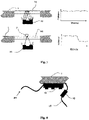
- a sensor element 12 for measuring sound waves is attached to the underside of a housing section 1 of the lamp.
- the sensor element 12 can be formed, for example, by a Doppler radar sensor module, a vibration sensor, a piezo sound pickup or a sensitive microphone.
- a drop of water 7 hits the outer surface of the lamp housing 1, sound waves are generated. These sound waves can be detected by the sensor 12.
- the singular event of a water drop creates a detectable amplitude compared to the background noise, as shown in the HF-time diagram. This event can be evaluated as the impact of a drop of water by downstream electronics. Due to the frequency of such singular events, a measure for the number of water drops per unit of time can even be determined.
- the figure 7 shows an embodiment of the moisture sensor with optical determination of water particles.
- a transparent cover 14 is in one Integrated housing section 1 of the lamp.
- a transmitter and receiver module 10 emits light, for example in the infrared range, and is reflected on a surface of the transparent cover 14 .
- the amount of reflected light at receiver 10 is reduced.
- the proportion of the measured reflected light is therefore reduced when a drop of water 7 rests on the transparent cover 14 .
- the difference in reflection can therefore be used to determine water droplets or a continuous film of moisture on the cover 14 .
- the figure 8 shows a variant of an embodiment with capacitive measurement.
- the combination of an electronic ballast is used to measure the relative capacitance between an LED module 16 and a portion of the lamp housing 1 .
- a line 18 is led out, which is connected to the housing section 1 with a bleeder resistor 19 .
- the discharge resistance 19 ensures that when the housing 1 is touched, a maximum touch current is not exceeded.
- the electronic ballast of the LEDs is connected to the line 20 with the LED module 16 .
- an electronic circuit is also provided inside the lamp, which receives the measurement signal from the moisture sensor and is set up to regulate the light output of the lamp.
- the streetlight changes its light distribution and/or light color and/or its luminous flux with the purpose of improving visibility for road users.
- the electronic control device in the street light is therefore set up to change the light output, in particular to change the light color towards a lower blue component and a higher red component, since the red component of the light leads to less glare. Although this degrades the color rendering compared to white light, the contrast is increased at the same time because road users are less dazzled.
- the level of lighting can also be reduced overall in order to reduce the glare of road users in rain, fog or snow.
- the lamps in the lamp can be easily dimmed by the control device of the lamp.
- the light distribution of the luminaire can also be modified to lower the illuminance on the rain-slicked surface, thereby reducing glare. In this case, the light distribution is changed to a wider light distribution.
- the automatic, weather-dependent adjustment of luminous flux, light color and/or light distribution therefore improves the visual comfort for road users in adverse weather conditions.
Landscapes
- Engineering & Computer Science (AREA)
- General Engineering & Computer Science (AREA)
- Investigating Or Analyzing Materials By The Use Of Electric Means (AREA)
- Investigating Or Analysing Materials By Optical Means (AREA)
Applications Claiming Priority (1)
| Application Number | Priority Date | Filing Date | Title |
|---|---|---|---|
| DE102020129841.2A DE102020129841A1 (de) | 2020-11-12 | 2020-11-12 | Straßenleuchte mit integriertem Feuchtigkeitssensor |
Publications (1)
| Publication Number | Publication Date |
|---|---|
| EP4001751A1 true EP4001751A1 (fr) | 2022-05-25 |
Family
ID=78820850
Family Applications (1)
| Application Number | Title | Priority Date | Filing Date |
|---|---|---|---|
| EP21207810.9A Pending EP4001751A1 (fr) | 2020-11-12 | 2021-11-11 | Luminaire d'éclairage public à capteur d'humidité intégré |
Country Status (2)
| Country | Link |
|---|---|
| EP (1) | EP4001751A1 (fr) |
| DE (1) | DE102020129841A1 (fr) |
Citations (7)
| Publication number | Priority date | Publication date | Assignee | Title |
|---|---|---|---|---|
| GB2412735A (en) * | 2004-04-01 | 2005-10-05 | Wrc Plc | Acoustic rain sensor |
| US20110054794A1 (en) * | 2009-08-28 | 2011-03-03 | Teder Rein S | Optical moisture sensor |
| WO2014147524A1 (fr) * | 2013-03-18 | 2014-09-25 | Koninklijke Philips N.V. | Procédés et appareils de gestion d'informations et de commande de réseaux d'éclairage extérieur |
| WO2016156563A1 (fr) * | 2015-04-01 | 2016-10-06 | Philips Lighting Holding B.V. | Luminaire détectant les précipitations |
| EP3611668A1 (fr) * | 2018-08-17 | 2020-02-19 | Fundacio per a la Universitat Oberta de Catalunya | Capteurs d'humidité |
| WO2020053342A1 (fr) * | 2018-09-12 | 2020-03-19 | Schreder S.A. | Système de luminaire permettant de déterminer des informations météorologiques |
| KR20200117648A (ko) * | 2019-04-05 | 2020-10-14 | 박순구 | 5세대 이동통신 기반에서의 스몰 셀 기지국 장치를 이용한 조명관리 서비스 시스템 |
Family Cites Families (6)
| Publication number | Priority date | Publication date | Assignee | Title |
|---|---|---|---|---|
| US6020744A (en) | 1997-11-04 | 2000-02-01 | Zellweger Uster, Inc. | Moisture sensor |
| CN101706459B (zh) | 2009-02-01 | 2013-05-01 | 杨厚荣 | 一种微波雷达水份传感器 |
| EP2233826B1 (fr) | 2009-03-17 | 2015-12-16 | Thorn Europhane S.A. | Unité d'éclairage et luminaire pour éclairage de route et/ou de rue |
| WO2012172470A1 (fr) | 2011-06-13 | 2012-12-20 | Koninklijke Philips Electronics N.V. | Système d'éclairage extérieur à commande adaptative et procédé de fonctionnement de celui-ci |
| US8739623B2 (en) | 2012-03-09 | 2014-06-03 | The University Of Kentucky Research Foundation | Moisture sensors on conductive substrates |
| WO2016060938A2 (fr) | 2014-10-08 | 2016-04-21 | RF Micron, Inc. | Étiquette(s) et capteurs d'humidité d'identification par radiofréquence (rfid) présentant une détection étendue par l'intermédiaire de capillaires |
-
2020
- 2020-11-12 DE DE102020129841.2A patent/DE102020129841A1/de active Pending
-
2021
- 2021-11-11 EP EP21207810.9A patent/EP4001751A1/fr active Pending
Patent Citations (7)
| Publication number | Priority date | Publication date | Assignee | Title |
|---|---|---|---|---|
| GB2412735A (en) * | 2004-04-01 | 2005-10-05 | Wrc Plc | Acoustic rain sensor |
| US20110054794A1 (en) * | 2009-08-28 | 2011-03-03 | Teder Rein S | Optical moisture sensor |
| WO2014147524A1 (fr) * | 2013-03-18 | 2014-09-25 | Koninklijke Philips N.V. | Procédés et appareils de gestion d'informations et de commande de réseaux d'éclairage extérieur |
| WO2016156563A1 (fr) * | 2015-04-01 | 2016-10-06 | Philips Lighting Holding B.V. | Luminaire détectant les précipitations |
| EP3611668A1 (fr) * | 2018-08-17 | 2020-02-19 | Fundacio per a la Universitat Oberta de Catalunya | Capteurs d'humidité |
| WO2020053342A1 (fr) * | 2018-09-12 | 2020-03-19 | Schreder S.A. | Système de luminaire permettant de déterminer des informations météorologiques |
| KR20200117648A (ko) * | 2019-04-05 | 2020-10-14 | 박순구 | 5세대 이동통신 기반에서의 스몰 셀 기지국 장치를 이용한 조명관리 서비스 시스템 |
Also Published As
| Publication number | Publication date |
|---|---|
| DE102020129841A1 (de) | 2022-05-12 |
Similar Documents
| Publication | Publication Date | Title |
|---|---|---|
| DE102010026564B4 (de) | Verfahren zum Detektieren der Sichtverhältnisse außerhalb eines Kraftfahrzeuges | |
| EP2542881B1 (fr) | Procédé et dispositif de détection de brouillard par spectroscopie | |
| EP0981470B1 (fr) | Capteur optique | |
| EP1424252B1 (fr) | Capteur optique | |
| DE3203091C2 (de) | Einrichtung zum Steuern der Scheibenreinigungsanlage eines Kraftfahrzeugs | |
| DE112004000035B4 (de) | Sensoranordnung zur Abstands- und/oder Geschwindigkeitsmessung | |
| EP3270362B1 (fr) | Détecteur d'incendie comprenant une chambre de mesure et un support de circuit destiné à disposer ensemble un détecteur d'incendie de la chambre de mesure et au moins un autre capteur destiné à détecter une grandeur de mesure dans l'environnement à l'extérieur du détecteur d'incendie | |
| DE102004001699A1 (de) | Brandmelder | |
| DE4300896C1 (de) | Verfahren und Vorrichtung zur Ermittlung des Fahrbahnoberflächenzustandes | |
| EP1068112A1 (fr) | Detecteur de pluie | |
| EP3128493A1 (fr) | Detecteur de fumee a ecran diffusant dote d'une chambre de mesure optique logee dans le boitier de detecteur et d'une surface reflechissante sur un cote interieur d'un capot de detecteur en tant que partie du boitier de detecteur | |
| DE102018121454A1 (de) | Anzeigevorrichtung mit Beschlagserkennungseinrichtung und Verfahren zum Betreiben einer Beschlagserkennung, ein Außenspiegel sowie ein Kraftfahrzeug | |
| DE102014004451A1 (de) | Verfahren und Sensoreinheit zur Detektion eines Benetzungsgrades einer Scheibe | |
| DE102016103722A1 (de) | Optische Sensorvorrichtung mit zusätzlicher kapazitiver Sensorik | |
| DE102011008556A1 (de) | Beleuchtungsvorrichtung für ein Fahrzeug und Verfahren zur Überwachung einer Beleuchtungsvorrichtung | |
| DE102010023856A1 (de) | Sensor zur berührungslosen Bestimmung der Fahrbahnbeschaffenheit und dessen Verwendung | |
| DE102008048090B3 (de) | Kanalsystem für Küchenabluft | |
| WO2019086246A1 (fr) | Procédé de détermination d'un type d'hydrométéore | |
| EP4001751A1 (fr) | Luminaire d'éclairage public à capteur d'humidité intégré | |
| DE102005010657B4 (de) | Objekterfassungsvorrichtung | |
| EP1421403A2 (fr) | Dispositif de detection optique | |
| EP1908652B1 (fr) | Détecteur de pluie | |
| DE19608535A1 (de) | Vorrichtung zum Erkennen von auf der Straße befindlichem Eis | |
| DE202005010570U1 (de) | Berührungsempfindlicher Sensor auf Basis eines Lichtleiters | |
| DE10049851C1 (de) | Vorrichtung zum Erkennen der strahlungsmäßigen Durchlässigkeit von vor Sensoren angebrachten Elementen |
Legal Events
| Date | Code | Title | Description |
|---|---|---|---|
| PUAI | Public reference made under article 153(3) epc to a published international application that has entered the european phase |
Free format text: ORIGINAL CODE: 0009012 |
|
| STAA | Information on the status of an ep patent application or granted ep patent |
Free format text: STATUS: THE APPLICATION HAS BEEN PUBLISHED |
|
| AK | Designated contracting states |
Kind code of ref document: A1 Designated state(s): AL AT BE BG CH CY CZ DE DK EE ES FI FR GB GR HR HU IE IS IT LI LT LU LV MC MK MT NL NO PL PT RO RS SE SI SK SM TR |
|
| STAA | Information on the status of an ep patent application or granted ep patent |
Free format text: STATUS: REQUEST FOR EXAMINATION WAS MADE |
|
| 17P | Request for examination filed |
Effective date: 20221110 |
|
| RBV | Designated contracting states (corrected) |
Designated state(s): AL AT BE BG CH CY CZ DE DK EE ES FI FR GB GR HR HU IE IS IT LI LT LU LV MC MK MT NL NO PL PT RO RS SE SI SK SM TR |
|
| STAA | Information on the status of an ep patent application or granted ep patent |
Free format text: STATUS: EXAMINATION IS IN PROGRESS |
|
| 17Q | First examination report despatched |
Effective date: 20240621 |