EP4001755B1 - Brennstoffbefeuerter brenner mit interner abgasrückführung - Google Patents
Brennstoffbefeuerter brenner mit interner abgasrückführung Download PDFInfo
- Publication number
- EP4001755B1 EP4001755B1 EP21207800.0A EP21207800A EP4001755B1 EP 4001755 B1 EP4001755 B1 EP 4001755B1 EP 21207800 A EP21207800 A EP 21207800A EP 4001755 B1 EP4001755 B1 EP 4001755B1
- Authority
- EP
- European Patent Office
- Prior art keywords
- combustion air
- burner
- chamber
- fuel
- exhaust gas
- Prior art date
- Legal status (The legal status is an assumption and is not a legal conclusion. Google has not performed a legal analysis and makes no representation as to the accuracy of the status listed.)
- Active
Links
Images


Classifications
-
- F—MECHANICAL ENGINEERING; LIGHTING; HEATING; WEAPONS; BLASTING
- F23—COMBUSTION APPARATUS; COMBUSTION PROCESSES
- F23D—BURNERS
- F23D14/00—Burners for combustion of a gas, e.g. of a gas stored under pressure as a liquid
- F23D14/20—Non-premix gas burners, i.e. in which gaseous fuel is mixed with combustion air on arrival at the combustion zone
-
- F—MECHANICAL ENGINEERING; LIGHTING; HEATING; WEAPONS; BLASTING
- F23—COMBUSTION APPARATUS; COMBUSTION PROCESSES
- F23C—METHODS OR APPARATUS FOR COMBUSTION USING FLUID FUEL OR SOLID FUEL SUSPENDED IN A CARRIER GAS OR AIR
- F23C9/00—Combustion apparatus characterised by arrangements for returning combustion products or flue gases to the combustion chamber
- F23C9/006—Combustion apparatus characterised by arrangements for returning combustion products or flue gases to the combustion chamber the recirculation taking place in the combustion chamber
-
- F—MECHANICAL ENGINEERING; LIGHTING; HEATING; WEAPONS; BLASTING
- F23—COMBUSTION APPARATUS; COMBUSTION PROCESSES
- F23D—BURNERS
- F23D11/00—Burners using a direct spraying action of liquid droplets or vaporised liquid into the combustion space
- F23D11/36—Details
- F23D11/40—Mixing tubes; Burner heads
- F23D11/402—Mixing chambers downstream of the nozzle
-
- F—MECHANICAL ENGINEERING; LIGHTING; HEATING; WEAPONS; BLASTING
- F23—COMBUSTION APPARATUS; COMBUSTION PROCESSES
- F23D—BURNERS
- F23D14/00—Burners for combustion of a gas, e.g. of a gas stored under pressure as a liquid
- F23D14/46—Details
- F23D14/62—Mixing devices; Mixing tubes
- F23D14/64—Mixing devices; Mixing tubes with injectors
-
- F—MECHANICAL ENGINEERING; LIGHTING; HEATING; WEAPONS; BLASTING
- F23—COMBUSTION APPARATUS; COMBUSTION PROCESSES
- F23D—BURNERS
- F23D17/00—Burners for combustion simultaneously or alternately of gaseous or liquid or pulverulent fuel
- F23D17/002—Burners for combustion simultaneously or alternately of gaseous or liquid or pulverulent fuel gaseous or liquid fuel
-
- F—MECHANICAL ENGINEERING; LIGHTING; HEATING; WEAPONS; BLASTING
- F23—COMBUSTION APPARATUS; COMBUSTION PROCESSES
- F23D—BURNERS
- F23D99/00—Subject matter not provided for in other groups of this subclass
-
- F—MECHANICAL ENGINEERING; LIGHTING; HEATING; WEAPONS; BLASTING
- F23—COMBUSTION APPARATUS; COMBUSTION PROCESSES
- F23C—METHODS OR APPARATUS FOR COMBUSTION USING FLUID FUEL OR SOLID FUEL SUSPENDED IN A CARRIER GAS OR AIR
- F23C2202/00—Fluegas recirculation
- F23C2202/30—Premixing fluegas with combustion air
-
- F—MECHANICAL ENGINEERING; LIGHTING; HEATING; WEAPONS; BLASTING
- F23—COMBUSTION APPARATUS; COMBUSTION PROCESSES
- F23D—BURNERS
- F23D2204/00—Burners adapted for simultaneous or alternative combustion having more than one fuel supply
- F23D2204/10—Burners adapted for simultaneous or alternative combustion having more than one fuel supply gaseous and liquid fuel
Definitions
- Disclosed aspects relate to fuel-fired burners having exhaust gas recycling.
- Oxides of nitrogen in the form of nitrogen oxide (i.e., NO) and nitrogen dioxide (NO 2 ) that can collectively be referred to as NOx, are generated by the burning of fossil fuels in the air which provides the nitrogen and the oxygen in the form of diatomic gases for forming NOx.
- NOx emitted from motor vehicles
- NOx from fossil fuel-fired industrial and commercial heating equipment e.g., furnaces, ovens
- NOx is known to emit NOx and thus, besides motor vehicles, is also recognized to be a major contributor to poor air quality and also smog.
- One conventional method to achieve EGR for industrial fuel-fired burners is to have the exhaust gas externally piped back from the exhaust stack to the combustion air intake where it can enter the combustion air fan to be mixed with the combustion air, where this exhaust gas and air mixture is sent to an air inlet of the burner.
- This known EGR arrangement needs additional piping and apparatus around (external to) the fuel-fired burner.
- This known EGR arrangement also involves an enlargement (or up-sizing) of the combustion air fan to handle the increased volume of the added flue gas. Larger air fans result in increased cost and also use more electricity per unit of heat produced.
- the fan materials of construction generally need upgrading to higher temperature capable alloys needed to handle the additional temperature and corrosive compositions generally present in the exhaust gas.
- EP 0 657 689 A1 discloses a fuel fired burner and method of its operation.
- the burner features a refractory lined burner housing having a fuel inlet coupled to a fuel pipe coupled to a burner nozzle.
- the burner features a hot flue gas recycle port and a combustion air inlet coupled to a combustion air nozzle.
- the combustion air nozzle circumscribes the fuel nozzle.
- the combustion air nozzle is configured to direct the combustion air into a chamber, thereby sucking flue gas through an annular gap into the chamber using a jet pump effect.
- the method and the burner according to the invention recognize in order to more economically implement EGR for fuel-fired burners, what is needed is a fuel-fired burner arrangement that lowers capital and operating costs by reducing the complexity of the EGR for the burner.
- the method and the burner according to the invention accomplish this by utilizing a jet pump arrangement that is located entirely inside the burner housing which eliminates the previously needed externally positioned hot exhaust gas piping, as well as the special fan and associated controls needed to mix the exhaust gas and the combustion air in proper proportions.
- the invention comprises a fuel-fired burner that includes a combustion air inlet for receiving combustion air coupled to a combustion air nozzle at an input to a second chamber within a burner housing spaced apart from a third chamber that is within the second chamber.
- the combustion air nozzle directs the combustion air into the third chamber.
- a fuel pipe having a fuel inlet is coupled to a burner nozzle secured to a burner mounting plate having a recycle port(s) for receiving hot exhaust gas provided to the second chamber.
- a jet pump located entirely inside the burner housing is configured to receive the exhaust gas from the second chamber.
- the jet pump operates by flowing the combustion air through the combustion air nozzle which suctions in the hot exhaust gas through the recycle port into an exhaust gas path bounded by the second chamber then into a gas mixing zone extending from an output of the combustion air nozzle to an input end of the third chamber for mixing the hot exhaust gas and the combustion air.
- the invention comprises a fuel-fired burner including EGR including a jet pump arrangement located entirely inside the burner housing that mixes exhaust gas with combustion air.
- the term "jet pump” refers to a passive pump (meaning the pump is not supplied any electrical power), where the jet pump is configured so that a small jet of a fluid that is in rapid motion lifts or otherwise moves by its impulse a large quantity of the fluid with which it mingles, in this case, exhaust gas.
- a jet pump thus operates by what is more generally called the Venturi effect.
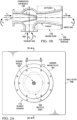
- FIG. 1A depicts a cross-sectional view of an example fuel-fired burner 100 shown as a fuel burner, according to an embodiment of the invention, including EGR comprising a jet pump arrangement provided entirely inside the burner housing 110 that mixes hot exhaust gas (also known as flue gas) received through a recycle port 164 formed (such as cut) in a burner mounting plate 161 to a recycled exhaust gas path (exhaust gas path) 165.
- the exhaust gas path 165 is bounded by an outside of a third chamber 168 and an inside of a second chamber 152 which enables the exhaust gas to flow into a gas mixing zone 178 as shown between the combustion air nozzle 136 and the input to the third chamber 168.
- the burner mounting plate 161 closes and seals the burner housing 110 (sealed other than the recycle port 164) on the side of the fuel-fired burner 100 having the burner nozzle 167.
- a fuel pipe 112 having a fuel inlet 111 is coupled to the burner nozzle 167.
- the fuel-fired burner 100 also includes another plate shown as a wall plate 156 that can represent a mounting wall in the customer's application for the fuel-fired burner 100.
- FIG. 1A shows the burner discharge sleeve 190 connected to the third chamber 168 by a weld region 169.
- the wall plate 156 is shown provided with a hole in its center region to enable insertion and thus the connection of the burner discharge sleeve 190 two the third chamber 168.
- a wall plate 156 with a hole in the center region is generally provided by the customer.
- the burner discharge sleeve 190 can be connected (e.g., welded) to the third chamber 168 as shown in FIG. 1A .
- the burner discharge sleeve 190 can be connected (e.g., welded) to the portion of the burner mounting plate 161 radially inside the recycle port 164. Both of these options allow for the fuel-fired burner 100 to be inserted into the customer's application chamber, such as a boiler, furnace or a heater, as a single unit.
- the wall plate 156 comprises a generic plate that represents the wall of another apparatus that receives heat from combustion performed by the fuel-fired burner 100, such as a boiler, furnace, or heater.
- the wall plate 156 generally has an opening large enough for the burner discharge sleeve 190 to pass through for mounting and still have enough surface area to place welded mounting studs on the wall plate 156.
- the burner mounting plate 161 generally includes mounting holes in the flange portion and the recycle port(s) 164 in the central area as shown in FIG. 2A described below.
- the burner mounting plate 161 is generally welded to the third chamber 168 as shown in FIG.
- the burner mounting plate 161 generally has a dimension generally being a diameter that is larger than the burner housing 110 (and the opening in the application wall) to create a mounting flange with holes for the studs of the wall plate 156 to pass through.
- the gas mixing zone 178 is between an output of a combustion air nozzle 136 and the burner mounting plate 161.
- the gas mixing zone 178 is for mixing hot exhaust gas with combustion air propelled by a combustion air fan 191 through ducting 192 to a combustion air inlet 113 that flows through the combustion air nozzle 136 to provide an internal EGR.
- combustion air fan 191 can also be located in other locations.
- the combustion air fan 191 is generally mounted away from the fuel-fired burner 100 and is ducted to the combustion air inlet 113 as shown in FIG. 1A . In some other arrangements, particularly if the air flow and pressure needs of the fuel-fired burner are lower, the combustion air fan 191 can be mounted directly onto the combustion air inlet 113 of the fuel-fired burner 100 so that no ducting 192 is needed.
- the burner discharge sleeve 190 can be made of a refractory material, such as configured as a block.
- the third chamber 168 would be extended slightly past the plane of the burner mounting plate 161 to slide as an open cylinder into an opening of this block.
- the internal flared shape for the burner discharge sleeve 190 is generally maintained whether the burner discharge sleeve 190 comprises a block or comprises sheet metal.
- the burner discharge sleeve 190 can represent any firing chamber that such a fuel-fired burner can fire into, such as a boiler or a heater.
- the size of the recycle port(s) 164 can be designed to determine the amount of exhaust flowing into the exhaust gas path 165 to be utilized by the jet pump.
- the recycle port(s) 164 can be sized and fixed in their size based on the amount of suction that is produced by the jet pump at a given combustion air flow rate.
- the materials of construction for the combustion air fan 191 can vary, but most combustion fans comprise steel.
- the size of the combustion air fan 191 is selected by the fuel-fired burner designer to meet the pressure and volume requirements for the combustion air.
- the design of the combustion air fan depends on the rotations per minute (rpm), wheel (or blower impeller) diameter, and the wheel width. A bigger wheel in the combustion fan provides a higher volume of combustion air.
- a combustion air fan 191 provides the proper combustion air volume and pressure through the combustion air inlet 113 into the burner housing 110, which is connected to the jet pump nozzle.
- the fuel, and the air can be controlled using individual valves on the air and fuel lines that are driven by a control signal from the system that monitors the stack exhaust oxygen level. Alternatively, such valves can be driven by controllers for measuring the air and fuel flow and holding these flows to a preset ratio.
- the air exiting the combustion air nozzle 136 functioning as a jet pump nozzle drives the jet pump to suck in exhaust gas from the recycle port 164 through the exhaust gas path 165 to the gas mixing zone 178.
- the jet pump utilizing a centrally positioned combustion air nozzle 136 creates a negative pressure condition when the combustion air fan 191 is operating.
- This negative pressure is operable to pull hot exhaust gas from the exhaust gas path 165 into the gas mixing zone 178 without the use of an additional fan or the need to up-size the combustion air fan 191.
- the exhaust gas enters the burner housing 110 as described above through the recycle port 164 in the burning mounting plate 161 of the burner, where the exhaust gas is suctioned into the exhaust gas path 165 then into the gas mixing zone 178 where it is mixed with the combustion air, and then passes through the third chamber 168 into the burner discharge sleeve 190 where the exhaust gas and air mixture can be mixed with fuel in various ways to provide a flame emerging from the burner nozzle 167.
- the resulting mixture of combustion air, exhaust gas, and fuel gas results in a combustion which produces a flame with a lower level of NOx emissions as compared to a flame without EGR. It is this lower level of NOx emissions provided by disclosed fuel-fired burners that is believed to make disclosed fuel-fired burners and related aspects particularly valuable. Disclosed aspects create this low NOx emissions result without the use of external hot exhaust gas piping, without the need for an upsized and/or upgraded combustion air fan, or additional controls, and without the associated safety concerns of having external hot exhaust piping running through the work area of a plant.
- the disclosed fuel-fired burner comprising a jet pump arrangement are sized and located entirely inside the burner housing 110.
- the combustion air fan 191 provides the proper combustion air volume and pressure into the burner housing 110, which is connected to the combustion air nozzle 136.
- the combustion air nozzle 136 ejects high velocity combustion air outward from its outlet including into the third chamber 168.
- the high velocity combustion air exiting the combustion air nozzle 136 drives the jet pump.
- the jet pump which can include more than one combustion air nozzle 136, creates a negative pressure condition when the combustion air fan 191 is operating that suctions in hot exhaust gas through the recycle port 164 through the exhaust gas path 165 to the gas mixing zone 178.
- a butterfly type control valve in the combustion air and fuel supply lines with control by a control system in the plant where the fuel-fired burner 100 is installed, where the control system can provide air and fuel ratio control for the fuel-fired burner 100.
- the fuel-fired burner 100 is connected to the plant's fuel and air control system. described combustion air blowers connected to the burner, and combustion air blowers connected via duct work.
- This is an alternative to the ducted air arrangement shown in FIG. 1A including ducting 192, where control valve for the air would typically be placed in the ducting 192 either by the manufacturer of the fuel-fired burner 100, or by others.
- This negative pressure suctions exhaust gas from the recycle port 164 to the exhaust gas path 165 into the gas mixing zone 178 without the use of an additional fan or the need to up-size the combustion air fan.
- the exhaust gas thus enters the burner housing 110 through recycle port(s) 164 in the burner mounting plate 161 which is transported by an interior sleeve referred to herein as the exhaust gas path 165, and is mixed in the gas mixing zone 178 with the combustion air, and then passes into the burner discharge sleeve 190 where it can be mixed with fuel in various ways to provide a flame at the burner outlet around the burner nozzle 167.
- FIG. 1B depicts a generalized jet pump, with the various regions of the jet pump with their respective reference numbers shown in FIG. 1A added to so that the jet pump can be considered to be a disclosed internal jet pump now shown as fuel-fired burner portion 150.
- a high velocity jet of gas shown as q 1 at a pressure of Pi corresponds to combustion air propelled by the combustion air fan 191 shown in FIG. 1A after it exits a combustion air nozzle 136 positioned in the burner housing 110 with an arrow depicting this combustion air 171 flowing in the gas mixing zone 178 as shown in FIG. 1A .
- the "qd" in FIG. 1B shown at a pressure of P d at an output of the fuel-fired burner portion 150 is the mixed gas (combustion air mixed with the hot recycled exhaust gas).
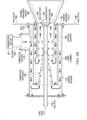
- FIGs. 2A-C depict various views of the example fuel-fired burner including EGR comprising a jet pump arrangement provided inside the burner housing that mixes hot exhaust gas with combustion air to provide internal exhaust gas recycle as shown in FIG. 1A , according to an embodiment.
- EGR comprising a jet pump arrangement provided inside the burner housing that mixes hot exhaust gas with combustion air to provide internal exhaust gas recycle as shown in FIG. 1A , according to an embodiment.
- FIG. 2A depicts a back view looking at the burner mounting plate 161 of an example fuel-fired burner and the wall plate 156 attached (shown as bolted on by bolts 173) to the burner mounting plate 161 that closes the burner housing 110.
- the recycle ports 164 are generally cut into the burning mounting plate 161, where the recycle ports 164 are shown only by example as being an annular-shaped region.
- FIG. 2B depicts a fuel-fired burner taken along the cut line B-B shown in FIG 2A .
- This FIG. depicts the direction of flow for the combustion air and the hot exhaust gas.
- the hot exhaust gas can be seen to make a turn inwards after flowing past the third chamber 168.
- FIG. 2C depicts a side cut view of the fuel-fired burner shown in FIG 2A .
- the third chamber 168 can be seen to be fully open on its side facing the output of the combustion air nozzle 136.
- a further benefit disclosed fuel-fired burners is that combustion air in the burner housing 110 cools the exhaust gas in the exhaust gas path framed by the second chamber 152.
- the second chamber 152 generally comprises steel which is known to be thermally conductive, the combustion air also cools the second chamber 152. This cooling of the hot exhaust gas also transfers heat to the combustion air used for combustion, which in turn, increases the overall thermal efficiency of the combustion process for the fueled-fired burner 100 compared to a conventional "piped" EGR system.
- Computational Fluid Dynamics (CFD) Simulation is one method that can be used to determine at least one design parameter for the fuel-fired burner 100.
- design parameters for simulation for a disclosed fuel-fired burner can include the internal geometry, sizes of the recycle ports 164, and an orientation of the combustion air nozzle 136 relative to the third chamber 168.
- Disclosed fuel-fired burners can be constructed of rolled and formed sheet metal, tubing, pipe such as comprising steel which can be welded, or can use another suitable high temperature tolerant material.
- the burner housing 110 generally comprises shaped sheet-metal.
- the various connections between components can be made by bolting on with flanches or by welding, such as bolting on with flanches of the burner mounting plate 161 to the end of the burner housing 110, and securing the combustion air nozzle 136 to the second chamber 152 using a weld.
- a jet pump that implements EGR can be applied to generally essentially any fuel-fired burner.
- a variety of fuel gases, such as natural gas or propane, or fuel liquids can be used.
Landscapes
- Engineering & Computer Science (AREA)
- Chemical & Material Sciences (AREA)
- Combustion & Propulsion (AREA)
- Mechanical Engineering (AREA)
- General Engineering & Computer Science (AREA)
- Combustion Of Fluid Fuel (AREA)
- Pre-Mixing And Non-Premixing Gas Burner (AREA)
Claims (14)
- Verfahren, umfassend:Bereitstellen eines brennstoffbeheizten Brenners (100), umfassend ein Brennergehäuse (110) mit einem Brennstoffeinlass (111), der mit einer Brennstoffleitung (112) verbunden ist, die mit einer Brennerdüse (167) verbunden ist, die an einer Brennermontageplatte (161) befestigt ist, die mindestens einen Rückführport (164) aufweist, einen Verbrennungslufteinlass (113) zum Empfangen von Verbrennungsluft, der mit einer Verbrennungsluftdüse (136) verbunden ist, die an Beginn einer Zufuhr zu einer zweiten Kammer (152) innerhalb des Brennergehäuses (110) positioniert ist, wobei die Verbrennungsluftdüse (136) einen Ausstoß aufweist, der von einer dritten Kammer (168) ebenfalls innerhalb der zweiten Kammer (152) beabstandet ist, wobei die Verbrennungsluftdüse (136) dazu konfiguriert ist, die Verbrennungsluft in die dritte Kammer (168) zu lenken, und eine Strahlpumpe, welche die Verbrennungsluftdüse (136), die zweite Kammer (152) und die dritte Kammer (168) umfasst und sich vollständig im Inneren des Brennergehäuses (110) befindet;Lenken der Verbrennungsluft von dem Verbrennungslufteinlass (113) durch die Verbrennungsluftdüse (136) unter Verwendung eines Verbrennungsluftgebläses (191);Lenken von Brennstoff durch die Brennstoffleitung (112) zu der Brennerdüse (167), um einen Verbrennungsprozess umzusetzen, der eine an der Brennerdüse (167) entspringende Flamme erzeugt, die ein heißes Abgas erzeugt, undBetreiben der Strahlpumpe, indem die Verbrennungsluft mit ausreichender Geschwindigkeit durch die Verbrennungsluftdüse (136) geströmt wird, um einen Impuls zu erzeugen, der das heiße Abgas durch den Rückführport (164) in die zweite Kammer (152), dann in eine sich von einem Ausstoß der Verbrennungsluftdüse (136) zu einem Zufuhrende der dritten Kammer (168) erstreckende Gasmischzone (178) ansaugt, die das angesaugte heiße Abgas mit der von der Verbrennungsluftdüse (136) empfangenen Verbrennungsluft mischt.
- Verfahren nach Anspruch 1, wobei die Strahlpumpe die Verbrennungsluftdüse (136) als Zufuhr für die Verbrennungsluft mit einem Abgaspfad (165) zum Empfangen von heißem Abgas, der zwischen der Außenseite der dritten Kammer (168) und einer Innenseite der zweiten Kammer (152) positioniert ist, umfasst.
- Verfahren nach Anspruch 1, wobei ein Flächenverhältnis der dritten Kammer (168) zu dem Ausstoß der Verbrennungsluftdüse (136) 1,2 zu 3 ist.
- Verfahren nach Anspruch 1, ferner umfassend einen Brennerauslaufstutzen (190), der an die Brennermontageplatte (161) oder an die dritte Kammer (168) geschweißt ist.
- Verfahren nach Anspruch 1, wobei der Rückführport (164) eine ringförmige Region umfasst.
- Verfahren nach Anspruch 2, wobei das in den Abgaspfad (165) gesaugte heiße Abgas von der Verbrennungsluft, welche an der Außenseite der zweiten Kammer (152) vorbeiströmt, gekühlt wird, wobei das Kühlen des heißen Abgases Wärme auf die Verbrennungsluft überträgt, um die Verbrennungsluft zu erwärmen, was eine Gesamtwärmeeffizienz des Verbrennungsprozesses erhöht.
- Verfahren nach Anspruch 1, ferner umfassend das Verwenden einer Simulation von Numerischer Strömungsmechanik (CFD), um mindestens einen Konstruktionsparameter für den brennstoffbeheizten Brenner (100) zu ermitteln.
- Verfahren nach Anspruch 7, wobei der mindestens eine Konstruktionsparameter eine Größe des Rückführports (164) und eine Ausrichtung der Verbrennungsluftdüse (136) relativ zu der dritten Kammer (168) umfasst.
- Brennstoffbeheizter Brenner (100), umfassend:ein Brennergehäuse (110);einen Verbrennungslufteinlass (113) zum Empfangen von Verbrennungsluft, der mit einer Verbrennungsluftdüse (136) verbunden ist;wobei die Verbrennungsluftdüse (136) an Beginn einer Zufuhr zu einer zweiten Kammer (152) innerhalb des Brennergehäuses (110) positioniert ist, wobei die Verbrennungsluftdüse (136) einen Ausstoß aufweist, der von einer dritten Kammer (168) ebenfalls innerhalb der zweiten Kammer (152) beabstandet ist, wobei die Verbrennungsluftdüse (136) dazu konfiguriert ist, die Verbrennungsluft in die dritte Kammer (168) zu lenken;einen Brennstoffeinlass (111), der zum Empfangen von Brennstoff mit einer Brennstoffleitung (112) verbunden ist, die mit einer Brennerdüse (167) verbunden ist, die an einer Brennermontageplatte (161) befestigt ist, die mindestens einen Rückführport (164) aufweist;einen Abgaspfad (165) zum Empfangen von heißem Abgas von dem Rückführport (164), undeine Strahlpumpe, welche die Verbrennungsluftdüse (136), die zweite Kammer (152) und die dritte Kammer (168) umfasst und sich vollständig im Inneren des Brennergehäuses (110) befindet und dazu konfiguriert ist, das heiße Abgas von dem Abgaspfad (165) zu empfangen,wobei der brennstoffbeheizte Brenner (100) dazu konfiguriert ist, die Strahlpumpe zu betreiben, indem die Verbrennungsluft durch die Verbrennungsluftdüse (136) mit ausreichender Geschwindigkeit geströmt wird, um einen Impuls zu erzeugen, der das heiße Abgas durch den Rückführport (164) in die zweite Kammer (152), dann in eine sich von einem Ausstoß der Verbrennungsluftdüse (136) zu einem Zufuhrende der dritten Kammer (168) erstreckende Gasmischzone (178) ansaugt, die das angesaugte heiße Abgas mit der von der Verbrennungsluftdüse (136) empfangenen Verbrennungsluft mischt.
- Brennstoffbeheizter Brenner nach Anspruch 9, wobei die Strahlpumpe die Verbrennungsluftdüse (136) als Zufuhr für die Verbrennungsluft mit einem Abgaspfad (165) zum Empfangen von heißem Abgas, der zwischen der Außenseite der dritten Kammer (168) und einer Innenseite der zweiten Kammer (152) positioniert ist, umfasst.
- Brennstoffbeheizter Brenner nach Anspruch 9, wobei ein Flächenverhältnis der dritten Kammer (168) zu dem Ausstoß der Verbrennungsluftdüse (136) 1,2 zu 3 ist.
- Brennstoffbeheizter Brenner nach Anspruch 9, ferner umfassend einen Brennerauslaufstutzen (190), der an die Brennermontageplatte (161) oder an die dritte Kammer (168) geschweißt ist.
- Brennstoffbeheizter Brenner nach Anspruch 9, wobei der Rückführport (164) eine ringförmige Region umfasst.
- Brennstoffbeheizter Brenner nach Anspruch 9, wobei eine Größe des Rückführports (164) ausschließlich eine passive Steuerung des Strömens des heißen Abgasstroms in die Strahlpumpe bereitstellt.
Priority Applications (1)
| Application Number | Priority Date | Filing Date | Title |
|---|---|---|---|
| EP24206247.9A EP4467873A3 (de) | 2020-11-24 | 2021-11-11 | Brennstoffbefeuerter brenner mit interner abgasrückführung |
Applications Claiming Priority (1)
| Application Number | Priority Date | Filing Date | Title |
|---|---|---|---|
| US17/103,123 US11732886B2 (en) | 2020-11-24 | 2020-11-24 | Fuel-fired burner with internal exhaust gas recycle |
Related Child Applications (1)
| Application Number | Title | Priority Date | Filing Date |
|---|---|---|---|
| EP24206247.9A Division EP4467873A3 (de) | 2020-11-24 | 2021-11-11 | Brennstoffbefeuerter brenner mit interner abgasrückführung |
Publications (2)
| Publication Number | Publication Date |
|---|---|
| EP4001755A1 EP4001755A1 (de) | 2022-05-25 |
| EP4001755B1 true EP4001755B1 (de) | 2024-10-16 |
Family
ID=78820586
Family Applications (2)
| Application Number | Title | Priority Date | Filing Date |
|---|---|---|---|
| EP21207800.0A Active EP4001755B1 (de) | 2020-11-24 | 2021-11-11 | Brennstoffbefeuerter brenner mit interner abgasrückführung |
| EP24206247.9A Pending EP4467873A3 (de) | 2020-11-24 | 2021-11-11 | Brennstoffbefeuerter brenner mit interner abgasrückführung |
Family Applications After (1)
| Application Number | Title | Priority Date | Filing Date |
|---|---|---|---|
| EP24206247.9A Pending EP4467873A3 (de) | 2020-11-24 | 2021-11-11 | Brennstoffbefeuerter brenner mit interner abgasrückführung |
Country Status (4)
| Country | Link |
|---|---|
| US (2) | US11732886B2 (de) |
| EP (2) | EP4001755B1 (de) |
| CN (1) | CN114543094B (de) |
| CA (1) | CA3138927A1 (de) |
Families Citing this family (4)
| Publication number | Priority date | Publication date | Assignee | Title |
|---|---|---|---|---|
| US11732886B2 (en) * | 2020-11-24 | 2023-08-22 | Honeywell International Inc. | Fuel-fired burner with internal exhaust gas recycle |
| KR102437328B1 (ko) * | 2021-12-22 | 2022-08-30 | 한국에너지기술연구원 | 내부 배기가스 재순환 예혼합형 공업용 가스연소기 및 그 작동방법 |
| CN116951400B (zh) * | 2023-07-24 | 2025-10-24 | 中船九江锅炉有限公司 | 一种具有内部废气再循环的燃料焚烧燃烧器 |
| CN119532750B (zh) * | 2024-12-18 | 2025-07-15 | 北京中科润宇环保科技股份有限公司 | 垃圾焚烧炉烟气的脱硝装置及脱硝方法 |
Family Cites Families (16)
| Publication number | Priority date | Publication date | Assignee | Title |
|---|---|---|---|---|
| USRE24862E (en) * | 1960-08-23 | Wall rack for mechanics tools | ||
| USRE24682E (en) | 1959-08-18 | johnson | ||
| US3174526A (en) * | 1960-08-23 | 1965-03-23 | Linde Robert Albert Von | Atomizing burner unit |
| US4130388A (en) * | 1976-09-15 | 1978-12-19 | Flynn Burner Corporation | Non-contaminating fuel burner |
| JPS5454339A (en) | 1977-10-08 | 1979-04-28 | Daido Steel Co Ltd | Combustion gas self-circulation buener with flame maintenance |
| US5413477A (en) | 1992-10-16 | 1995-05-09 | Gas Research Institute | Staged air, low NOX burner with internal recuperative flue gas recirculation |
| ATE484713T1 (de) * | 2002-03-16 | 2010-10-15 | Exxonmobil Chem Patents Inc | Lösbarer zündelementdeckel für einen brenner |
| CN101900333A (zh) * | 2010-07-22 | 2010-12-01 | 黄晓华 | 高温低氧燃烧器 |
| CN103277795B (zh) * | 2013-05-27 | 2015-05-20 | 中国科学院广州能源研究所 | 可调节烟气自身再循环燃气燃烧器 |
| KR101512352B1 (ko) | 2013-11-12 | 2015-04-23 | 한국생산기술연구원 | 연소가스의 내부 재순환을 통한 초저질소산화물 연소장치 및 이의 운전방법 |
| US10451271B2 (en) | 2017-12-20 | 2019-10-22 | Honeywell International Inc. | Staged fuel burner with jet induced exhaust gas recycle |
| US10533741B2 (en) | 2017-12-20 | 2020-01-14 | Honeywell International Inc. | Low NOx burner with exhaust gas recycle and partial premix |
| CN108662576A (zh) * | 2018-06-13 | 2018-10-16 | 上海华之邦科技股份有限公司 | 一种烟气自动内循环式低氮燃烧系统 |
| CN211290051U (zh) * | 2019-09-11 | 2020-08-18 | 向顺华 | 一种烟气自循环型低氮无氧化烧嘴 |
| CN111520716A (zh) * | 2020-06-09 | 2020-08-11 | 江苏蓝创环保科技有限公司 | 一种强化烟气内循环燃气燃烧器 |
| US11732886B2 (en) * | 2020-11-24 | 2023-08-22 | Honeywell International Inc. | Fuel-fired burner with internal exhaust gas recycle |
-
2020
- 2020-11-24 US US17/103,123 patent/US11732886B2/en active Active
-
2021
- 2021-11-11 EP EP21207800.0A patent/EP4001755B1/de active Active
- 2021-11-11 EP EP24206247.9A patent/EP4467873A3/de active Pending
- 2021-11-12 CN CN202111344266.4A patent/CN114543094B/zh active Active
- 2021-11-12 CA CA3138927A patent/CA3138927A1/en active Pending
-
2023
- 2023-08-02 US US18/363,941 patent/US12338992B2/en active Active
Also Published As
| Publication number | Publication date |
|---|---|
| CA3138927A1 (en) | 2022-05-24 |
| EP4001755A1 (de) | 2022-05-25 |
| CN114543094A (zh) | 2022-05-27 |
| CN114543094B (zh) | 2026-01-23 |
| EP4467873A2 (de) | 2024-11-27 |
| US12338992B2 (en) | 2025-06-24 |
| EP4467873A3 (de) | 2025-02-05 |
| US20220163197A1 (en) | 2022-05-26 |
| US20240019119A1 (en) | 2024-01-18 |
| US11732886B2 (en) | 2023-08-22 |
Similar Documents
| Publication | Publication Date | Title |
|---|---|---|
| EP4001755B1 (de) | Brennstoffbefeuerter brenner mit interner abgasrückführung | |
| EP3502559B1 (de) | Nox-armer brenner mit abgasrückführung und teilvormischung | |
| US4659305A (en) | Flue gas recirculation system for fire tube boilers and burner therefor | |
| US8591221B2 (en) | Combustion blower control for modulating furnace | |
| US5520537A (en) | High-output tube burner | |
| EP3311074B1 (de) | Brenner mit verbrennungsluftbetriebener strahlpumpe | |
| JP3686487B2 (ja) | 元混合型ガス燃焼装置 | |
| EP3044509B1 (de) | Verbrennungsverfahren und industriebrenner | |
| US6415744B1 (en) | Combustion boiler | |
| KR20110031207A (ko) | 내부 연도가스 재순환을 갖는 노 시스템 | |
| US5666944A (en) | Water heating apparatus with passive flue gas recirculation | |
| SE512645C2 (sv) | Portabel brännare | |
| US10451271B2 (en) | Staged fuel burner with jet induced exhaust gas recycle | |
| KR100792346B1 (ko) | 직화방식 선박도장 건조장치 | |
| EP2682675B1 (de) | Rauchgaswiederverwertungssystem mit festen Öffnungen | |
| US6223740B1 (en) | Fuel-fired furnace with self-cooling draft inducer fan | |
| KR20210055202A (ko) | 가스 퍼니스 | |
| EP3921575B1 (de) | Rekuperative strahlrohrbrenneranordnung | |
| KR100795595B1 (ko) | 가스 연소장치 | |
| CN223020339U (zh) | 一种鼓风组件、燃烧器及燃气灶 | |
| EP1731835A1 (de) | Vorrichtung zur Verbrennung von vergasten flüssigen Brennstoffen | |
| CN211345295U (zh) | 一种无级变速燃烧器 | |
| US20240310039A1 (en) | Gas furnace with heat exchanger | |
| CN114738748A (zh) | 一种通道式矩形阵列气体混合器 | |
| EP2119962A1 (de) | Strahlungsrohr-Wärmeanordnung |
Legal Events
| Date | Code | Title | Description |
|---|---|---|---|
| PUAI | Public reference made under article 153(3) epc to a published international application that has entered the european phase |
Free format text: ORIGINAL CODE: 0009012 |
|
| STAA | Information on the status of an ep patent application or granted ep patent |
Free format text: STATUS: REQUEST FOR EXAMINATION WAS MADE |
|
| 17P | Request for examination filed |
Effective date: 20211111 |
|
| AK | Designated contracting states |
Kind code of ref document: A1 Designated state(s): AL AT BE BG CH CY CZ DE DK EE ES FI FR GB GR HR HU IE IS IT LI LT LU LV MC MK MT NL NO PL PT RO RS SE SI SK SM TR |
|
| P01 | Opt-out of the competence of the unified patent court (upc) registered |
Effective date: 20230414 |
|
| GRAP | Despatch of communication of intention to grant a patent |
Free format text: ORIGINAL CODE: EPIDOSNIGR1 |
|
| STAA | Information on the status of an ep patent application or granted ep patent |
Free format text: STATUS: GRANT OF PATENT IS INTENDED |
|
| RIC1 | Information provided on ipc code assigned before grant |
Ipc: F23D 99/00 20100101ALI20240502BHEP Ipc: F23D 14/64 20060101ALI20240502BHEP Ipc: F23D 14/20 20060101ALI20240502BHEP Ipc: F23C 9/00 20060101AFI20240502BHEP |
|
| INTG | Intention to grant announced |
Effective date: 20240605 |
|
| GRAS | Grant fee paid |
Free format text: ORIGINAL CODE: EPIDOSNIGR3 |
|
| GRAA | (expected) grant |
Free format text: ORIGINAL CODE: 0009210 |
|
| STAA | Information on the status of an ep patent application or granted ep patent |
Free format text: STATUS: THE PATENT HAS BEEN GRANTED |
|
| AK | Designated contracting states |
Kind code of ref document: B1 Designated state(s): AL AT BE BG CH CY CZ DE DK EE ES FI FR GB GR HR HU IE IS IT LI LT LU LV MC MK MT NL NO PL PT RO RS SE SI SK SM TR |
|
| REG | Reference to a national code |
Ref country code: GB Ref legal event code: FG4D |
|
| REG | Reference to a national code |
Ref country code: CH Ref legal event code: EP |
|
| REG | Reference to a national code |
Ref country code: IE Ref legal event code: FG4D |
|
| REG | Reference to a national code |
Ref country code: DE Ref legal event code: R096 Ref document number: 602021020290 Country of ref document: DE |
|
| REG | Reference to a national code |
Ref country code: LT Ref legal event code: MG9D |
|
| REG | Reference to a national code |
Ref country code: NL Ref legal event code: MP Effective date: 20241016 |
|
| REG | Reference to a national code |
Ref country code: AT Ref legal event code: MK05 Ref document number: 1733174 Country of ref document: AT Kind code of ref document: T Effective date: 20241016 |
|
| PG25 | Lapsed in a contracting state [announced via postgrant information from national office to epo] |
Ref country code: NL Free format text: LAPSE BECAUSE OF FAILURE TO SUBMIT A TRANSLATION OF THE DESCRIPTION OR TO PAY THE FEE WITHIN THE PRESCRIBED TIME-LIMIT Effective date: 20241016 |
|
| PG25 | Lapsed in a contracting state [announced via postgrant information from national office to epo] |
Ref country code: NL Free format text: LAPSE BECAUSE OF FAILURE TO SUBMIT A TRANSLATION OF THE DESCRIPTION OR TO PAY THE FEE WITHIN THE PRESCRIBED TIME-LIMIT Effective date: 20241016 |
|
| PG25 | Lapsed in a contracting state [announced via postgrant information from national office to epo] |
Ref country code: IS Free format text: LAPSE BECAUSE OF FAILURE TO SUBMIT A TRANSLATION OF THE DESCRIPTION OR TO PAY THE FEE WITHIN THE PRESCRIBED TIME-LIMIT Effective date: 20250216 Ref country code: PT Free format text: LAPSE BECAUSE OF FAILURE TO SUBMIT A TRANSLATION OF THE DESCRIPTION OR TO PAY THE FEE WITHIN THE PRESCRIBED TIME-LIMIT Effective date: 20250217 Ref country code: HR Free format text: LAPSE BECAUSE OF FAILURE TO SUBMIT A TRANSLATION OF THE DESCRIPTION OR TO PAY THE FEE WITHIN THE PRESCRIBED TIME-LIMIT Effective date: 20241016 |
|
| PG25 | Lapsed in a contracting state [announced via postgrant information from national office to epo] |
Ref country code: FI Free format text: LAPSE BECAUSE OF FAILURE TO SUBMIT A TRANSLATION OF THE DESCRIPTION OR TO PAY THE FEE WITHIN THE PRESCRIBED TIME-LIMIT Effective date: 20241016 |
|
| PG25 | Lapsed in a contracting state [announced via postgrant information from national office to epo] |
Ref country code: BG Free format text: LAPSE BECAUSE OF FAILURE TO SUBMIT A TRANSLATION OF THE DESCRIPTION OR TO PAY THE FEE WITHIN THE PRESCRIBED TIME-LIMIT Effective date: 20241016 |
|
| PG25 | Lapsed in a contracting state [announced via postgrant information from national office to epo] |
Ref country code: ES Free format text: LAPSE BECAUSE OF FAILURE TO SUBMIT A TRANSLATION OF THE DESCRIPTION OR TO PAY THE FEE WITHIN THE PRESCRIBED TIME-LIMIT Effective date: 20241016 |
|
| PG25 | Lapsed in a contracting state [announced via postgrant information from national office to epo] |
Ref country code: NO Free format text: LAPSE BECAUSE OF FAILURE TO SUBMIT A TRANSLATION OF THE DESCRIPTION OR TO PAY THE FEE WITHIN THE PRESCRIBED TIME-LIMIT Effective date: 20250116 |
|
| PG25 | Lapsed in a contracting state [announced via postgrant information from national office to epo] |
Ref country code: GR Free format text: LAPSE BECAUSE OF FAILURE TO SUBMIT A TRANSLATION OF THE DESCRIPTION OR TO PAY THE FEE WITHIN THE PRESCRIBED TIME-LIMIT Effective date: 20250117 Ref country code: LV Free format text: LAPSE BECAUSE OF FAILURE TO SUBMIT A TRANSLATION OF THE DESCRIPTION OR TO PAY THE FEE WITHIN THE PRESCRIBED TIME-LIMIT Effective date: 20241016 Ref country code: AT Free format text: LAPSE BECAUSE OF FAILURE TO SUBMIT A TRANSLATION OF THE DESCRIPTION OR TO PAY THE FEE WITHIN THE PRESCRIBED TIME-LIMIT Effective date: 20241016 |
|
| PG25 | Lapsed in a contracting state [announced via postgrant information from national office to epo] |
Ref country code: PL Free format text: LAPSE BECAUSE OF FAILURE TO SUBMIT A TRANSLATION OF THE DESCRIPTION OR TO PAY THE FEE WITHIN THE PRESCRIBED TIME-LIMIT Effective date: 20241016 |
|
| PG25 | Lapsed in a contracting state [announced via postgrant information from national office to epo] |
Ref country code: RS Free format text: LAPSE BECAUSE OF FAILURE TO SUBMIT A TRANSLATION OF THE DESCRIPTION OR TO PAY THE FEE WITHIN THE PRESCRIBED TIME-LIMIT Effective date: 20250116 |
|
| REG | Reference to a national code |
Ref country code: CH Ref legal event code: PL |
|
| PG25 | Lapsed in a contracting state [announced via postgrant information from national office to epo] |
Ref country code: SM Free format text: LAPSE BECAUSE OF FAILURE TO SUBMIT A TRANSLATION OF THE DESCRIPTION OR TO PAY THE FEE WITHIN THE PRESCRIBED TIME-LIMIT Effective date: 20241016 |
|
| PG25 | Lapsed in a contracting state [announced via postgrant information from national office to epo] |
Ref country code: MC Free format text: LAPSE BECAUSE OF FAILURE TO SUBMIT A TRANSLATION OF THE DESCRIPTION OR TO PAY THE FEE WITHIN THE PRESCRIBED TIME-LIMIT Effective date: 20241016 |
|
| PG25 | Lapsed in a contracting state [announced via postgrant information from national office to epo] |
Ref country code: DK Free format text: LAPSE BECAUSE OF FAILURE TO SUBMIT A TRANSLATION OF THE DESCRIPTION OR TO PAY THE FEE WITHIN THE PRESCRIBED TIME-LIMIT Effective date: 20241016 |
|
| PG25 | Lapsed in a contracting state [announced via postgrant information from national office to epo] |
Ref country code: LU Free format text: LAPSE BECAUSE OF NON-PAYMENT OF DUE FEES Effective date: 20241111 |
|
| REG | Reference to a national code |
Ref country code: CH Ref legal event code: PL |
|
| REG | Reference to a national code |
Ref country code: DE Ref legal event code: R097 Ref document number: 602021020290 Country of ref document: DE |
|
| PG25 | Lapsed in a contracting state [announced via postgrant information from national office to epo] |
Ref country code: EE Free format text: LAPSE BECAUSE OF FAILURE TO SUBMIT A TRANSLATION OF THE DESCRIPTION OR TO PAY THE FEE WITHIN THE PRESCRIBED TIME-LIMIT Effective date: 20241016 |
|
| PG25 | Lapsed in a contracting state [announced via postgrant information from national office to epo] |
Ref country code: CH Free format text: LAPSE BECAUSE OF NON-PAYMENT OF DUE FEES Effective date: 20241130 |
|
| PG25 | Lapsed in a contracting state [announced via postgrant information from national office to epo] |
Ref country code: RO Free format text: LAPSE BECAUSE OF FAILURE TO SUBMIT A TRANSLATION OF THE DESCRIPTION OR TO PAY THE FEE WITHIN THE PRESCRIBED TIME-LIMIT Effective date: 20241016 |
|
| PG25 | Lapsed in a contracting state [announced via postgrant information from national office to epo] |
Ref country code: SK Free format text: LAPSE BECAUSE OF FAILURE TO SUBMIT A TRANSLATION OF THE DESCRIPTION OR TO PAY THE FEE WITHIN THE PRESCRIBED TIME-LIMIT Effective date: 20241016 |
|
| PG25 | Lapsed in a contracting state [announced via postgrant information from national office to epo] |
Ref country code: CZ Free format text: LAPSE BECAUSE OF FAILURE TO SUBMIT A TRANSLATION OF THE DESCRIPTION OR TO PAY THE FEE WITHIN THE PRESCRIBED TIME-LIMIT Effective date: 20241016 |
|
| PG25 | Lapsed in a contracting state [announced via postgrant information from national office to epo] |
Ref country code: IT Free format text: LAPSE BECAUSE OF FAILURE TO SUBMIT A TRANSLATION OF THE DESCRIPTION OR TO PAY THE FEE WITHIN THE PRESCRIBED TIME-LIMIT Effective date: 20241016 |
|
| PLBE | No opposition filed within time limit |
Free format text: ORIGINAL CODE: 0009261 |
|
| STAA | Information on the status of an ep patent application or granted ep patent |
Free format text: STATUS: NO OPPOSITION FILED WITHIN TIME LIMIT |
|
| REG | Reference to a national code |
Ref country code: BE Ref legal event code: MM Effective date: 20241130 |
|
| PG25 | Lapsed in a contracting state [announced via postgrant information from national office to epo] |
Ref country code: SE Free format text: LAPSE BECAUSE OF FAILURE TO SUBMIT A TRANSLATION OF THE DESCRIPTION OR TO PAY THE FEE WITHIN THE PRESCRIBED TIME-LIMIT Effective date: 20241016 |
|
| 26N | No opposition filed |
Effective date: 20250717 |
|
| PG25 | Lapsed in a contracting state [announced via postgrant information from national office to epo] |
Ref country code: BE Free format text: LAPSE BECAUSE OF NON-PAYMENT OF DUE FEES Effective date: 20241130 |
|
| PG25 | Lapsed in a contracting state [announced via postgrant information from national office to epo] |
Ref country code: FR Free format text: LAPSE BECAUSE OF NON-PAYMENT OF DUE FEES Effective date: 20241216 |
|
| PG25 | Lapsed in a contracting state [announced via postgrant information from national office to epo] |
Ref country code: IE Free format text: LAPSE BECAUSE OF NON-PAYMENT OF DUE FEES Effective date: 20241111 |
|
| PGFP | Annual fee paid to national office [announced via postgrant information from national office to epo] |
Ref country code: DE Payment date: 20251126 Year of fee payment: 5 |
|
| PGFP | Annual fee paid to national office [announced via postgrant information from national office to epo] |
Ref country code: GB Payment date: 20251125 Year of fee payment: 5 |
|
| PG25 | Lapsed in a contracting state [announced via postgrant information from national office to epo] |
Ref country code: HU Free format text: LAPSE BECAUSE OF FAILURE TO SUBMIT A TRANSLATION OF THE DESCRIPTION OR TO PAY THE FEE WITHIN THE PRESCRIBED TIME-LIMIT; INVALID AB INITIO Effective date: 20211111 |
|
| PG25 | Lapsed in a contracting state [announced via postgrant information from national office to epo] |
Ref country code: CY Free format text: LAPSE BECAUSE OF FAILURE TO SUBMIT A TRANSLATION OF THE DESCRIPTION OR TO PAY THE FEE WITHIN THE PRESCRIBED TIME-LIMIT; INVALID AB INITIO Effective date: 20211111 |