EP4001771B1 - Système de verrouillage de porte modulaire - Google Patents
Système de verrouillage de porte modulaire Download PDFInfo
- Publication number
- EP4001771B1 EP4001771B1 EP21206107.1A EP21206107A EP4001771B1 EP 4001771 B1 EP4001771 B1 EP 4001771B1 EP 21206107 A EP21206107 A EP 21206107A EP 4001771 B1 EP4001771 B1 EP 4001771B1
- Authority
- EP
- European Patent Office
- Prior art keywords
- door
- opening
- rotating hook
- lock system
- prong
- Prior art date
- Legal status (The legal status is an assumption and is not a legal conclusion. Google has not performed a legal analysis and makes no representation as to the accuracy of the status listed.)
- Active
Links
Images


Classifications
-
- E—FIXED CONSTRUCTIONS
- E05—LOCKS; KEYS; WINDOW OR DOOR FITTINGS; SAFES
- E05B—LOCKS; ACCESSORIES THEREFOR; HANDCUFFS
- E05B47/00—Operating or controlling locks or other fastening devices by electric or magnetic means
- E05B47/0001—Operating or controlling locks or other fastening devices by electric or magnetic means with electric actuators; Constructional features thereof
- E05B47/0012—Operating or controlling locks or other fastening devices by electric or magnetic means with electric actuators; Constructional features thereof with rotary electromotors
-
- E—FIXED CONSTRUCTIONS
- E05—LOCKS; KEYS; WINDOW OR DOOR FITTINGS; SAFES
- E05B—LOCKS; ACCESSORIES THEREFOR; HANDCUFFS
- E05B17/00—Accessories in connection with locks
- E05B17/0025—Devices for forcing the wing firmly against its seat or to initiate the opening of the wing
- E05B17/0029—Devices for forcing the wing firmly against its seat or to initiate the opening of the wing motor-operated
-
- E—FIXED CONSTRUCTIONS
- E05—LOCKS; KEYS; WINDOW OR DOOR FITTINGS; SAFES
- E05B—LOCKS; ACCESSORIES THEREFOR; HANDCUFFS
- E05B63/00—Locks or fastenings with special structural characteristics
- E05B63/0056—Locks with adjustable or exchangeable lock parts
-
- E—FIXED CONSTRUCTIONS
- E05—LOCKS; KEYS; WINDOW OR DOOR FITTINGS; SAFES
- E05B—LOCKS; ACCESSORIES THEREFOR; HANDCUFFS
- E05B65/00—Locks or fastenings for special use
-
- E—FIXED CONSTRUCTIONS
- E05—LOCKS; KEYS; WINDOW OR DOOR FITTINGS; SAFES
- E05C—BOLTS OR FASTENING DEVICES FOR WINGS, SPECIALLY FOR DOORS OR WINDOWS
- E05C19/00—Other devices specially designed for securing wings, e.g. with suction cups
- E05C19/02—Automatic catches, i.e. released by pull or pressure on the wing
- E05C19/024—Automatic catches, i.e. released by pull or pressure on the wing with a bifurcated latch
-
- E—FIXED CONSTRUCTIONS
- E05—LOCKS; KEYS; WINDOW OR DOOR FITTINGS; SAFES
- E05C—BOLTS OR FASTENING DEVICES FOR WINGS, SPECIALLY FOR DOORS OR WINDOWS
- E05C3/00—Fastening devices with bolts moving pivotally or rotatively
- E05C3/02—Fastening devices with bolts moving pivotally or rotatively without latching action
-
- E—FIXED CONSTRUCTIONS
- E05—LOCKS; KEYS; WINDOW OR DOOR FITTINGS; SAFES
- E05C—BOLTS OR FASTENING DEVICES FOR WINGS, SPECIALLY FOR DOORS OR WINDOWS
- E05C3/00—Fastening devices with bolts moving pivotally or rotatively
- E05C3/12—Fastening devices with bolts moving pivotally or rotatively with latching action
- E05C3/16—Fastening devices with bolts moving pivotally or rotatively with latching action with operating handle or equivalent member moving otherwise than rigidly with the latch
- E05C3/22—Fastening devices with bolts moving pivotally or rotatively with latching action with operating handle or equivalent member moving otherwise than rigidly with the latch the bolt being spring controlled
- E05C3/24—Fastening devices with bolts moving pivotally or rotatively with latching action with operating handle or equivalent member moving otherwise than rigidly with the latch the bolt being spring controlled in the form of a bifurcated member
-
- F—MECHANICAL ENGINEERING; LIGHTING; HEATING; WEAPONS; BLASTING
- F24—HEATING; RANGES; VENTILATING
- F24C—DOMESTIC STOVES OR RANGES ; DETAILS OF DOMESTIC STOVES OR RANGES, OF GENERAL APPLICATION
- F24C15/00—Details
- F24C15/02—Doors specially adapted for stoves or ranges
- F24C15/022—Latches
-
- A—HUMAN NECESSITIES
- A47—FURNITURE; DOMESTIC ARTICLES OR APPLIANCES; COFFEE MILLS; SPICE MILLS; SUCTION CLEANERS IN GENERAL
- A47L—DOMESTIC WASHING OR CLEANING; SUCTION CLEANERS IN GENERAL
- A47L15/00—Washing or rinsing machines for crockery or tableware
- A47L15/42—Details
- A47L15/4251—Details of the casing
- A47L15/4257—Details of the loading door
- A47L15/4259—Arrangements of locking or security/safety devices for doors, e.g. door latches, switch to stop operation when door is open
-
- D—TEXTILES; PAPER
- D06—TREATMENT OF TEXTILES OR THE LIKE; LAUNDERING; FLEXIBLE MATERIALS NOT OTHERWISE PROVIDED FOR
- D06F—LAUNDERING, DRYING, IRONING, PRESSING OR FOLDING TEXTILE ARTICLES
- D06F39/00—Details of washing machines not specific to a single type of machines covered by groups D06F9/00 - D06F27/00
- D06F39/12—Casings; Tubs
- D06F39/14—Doors or covers; Securing means therefor
-
- E—FIXED CONSTRUCTIONS
- E05—LOCKS; KEYS; WINDOW OR DOOR FITTINGS; SAFES
- E05B—LOCKS; ACCESSORIES THEREFOR; HANDCUFFS
- E05B47/00—Operating or controlling locks or other fastening devices by electric or magnetic means
- E05B47/0001—Operating or controlling locks or other fastening devices by electric or magnetic means with electric actuators; Constructional features thereof
- E05B2047/0014—Constructional features of actuators or power transmissions therefor
- E05B2047/0015—Output elements of actuators
- E05B2047/0016—Output elements of actuators with linearly reciprocating motion
-
- E—FIXED CONSTRUCTIONS
- E05—LOCKS; KEYS; WINDOW OR DOOR FITTINGS; SAFES
- E05B—LOCKS; ACCESSORIES THEREFOR; HANDCUFFS
- E05B47/00—Operating or controlling locks or other fastening devices by electric or magnetic means
- E05B47/0001—Operating or controlling locks or other fastening devices by electric or magnetic means with electric actuators; Constructional features thereof
- E05B2047/0014—Constructional features of actuators or power transmissions therefor
- E05B2047/0015—Output elements of actuators
- E05B2047/0017—Output elements of actuators with rotary motion
-
- E—FIXED CONSTRUCTIONS
- E05—LOCKS; KEYS; WINDOW OR DOOR FITTINGS; SAFES
- E05B—LOCKS; ACCESSORIES THEREFOR; HANDCUFFS
- E05B47/00—Operating or controlling locks or other fastening devices by electric or magnetic means
- E05B47/0001—Operating or controlling locks or other fastening devices by electric or magnetic means with electric actuators; Constructional features thereof
- E05B2047/0014—Constructional features of actuators or power transmissions therefor
- E05B2047/0018—Details of actuator transmissions
- E05B2047/002—Geared transmissions
-
- E—FIXED CONSTRUCTIONS
- E05—LOCKS; KEYS; WINDOW OR DOOR FITTINGS; SAFES
- E05B—LOCKS; ACCESSORIES THEREFOR; HANDCUFFS
- E05B47/00—Operating or controlling locks or other fastening devices by electric or magnetic means
- E05B2047/0048—Circuits, feeding, monitoring
- E05B2047/0067—Monitoring
- E05B2047/0068—Door closed
-
- E—FIXED CONSTRUCTIONS
- E05—LOCKS; KEYS; WINDOW OR DOOR FITTINGS; SAFES
- E05B—LOCKS; ACCESSORIES THEREFOR; HANDCUFFS
- E05B47/00—Operating or controlling locks or other fastening devices by electric or magnetic means
- E05B2047/0048—Circuits, feeding, monitoring
- E05B2047/0067—Monitoring
- E05B2047/0069—Monitoring bolt position
Definitions
- the present invention relates to a modular door-lock system for a household appliance.
- the invention relates to a door-lock system in which it is possible to install several door lock systems, designed and manufactured in particular for domestic and industrial ovens.
- ovens As is well known, there are currently different types of ovens. For example, microwave, pyrolytic, high-end ovens, and the like are known. In some ovens, such as pyrolytic ones, it is necessary to have a closing system that is particularly safe, in consideration of the high temperatures of the oven. On the other hand, for example, high-end ovens have an automatic closing and opening system.
- top module and bottom module
- top module and bottom module
- the door-lock devices must be made in such a way as to adapt to the different needs. This implies that manufacturers must include in their catalog many different types of door-lock devices, each suitable for different needs and types of ovens.
- an object of the present invention to propose a door-lock device that can be configured according to the installation requirements in household appliances in particular ovens.
- a further object of the present invention is to propose a door-lock device, which can have a single architecture and which can therefore be used, according to how it is equipped, as a top module, or an upper module, or a bottom module, or a lower module.
- Another object of the invention is to propose a door-lock device that can be easy to assemble.
- a door-lock system for a household appliance wherein said household appliance is of the type comprising a frame and a door hinged to said frame, and wherein said door-lock system comprises: an engaging member, fixable to said door of said household appliance, and comprising a prong and a security member arranged substantially parallel to said prong; and a door-lock device, comprising a containment casing fixable to the frame of said household appliance, a blocking group, intended to engage with and hold said engaging member, which in its turn comprises a rotating hook, arranged within said containment casing, and capable of moving from a resting position, wherein said prong is not engaged with said rotating hook, to an operating position, wherein said prong is engaged and blocked with said rotating hook, so as to hold said door closed; a blocking member, related to said rotating hook, such that, when said rotating hook is in said resting position, said blocking member assumes a closing position, preventing the insertion of said security member within said door-lock device, and that,
- said containment casing comprises a base and a lid, arranged on said base, for closing said containment casing, wherein said base has a first opening and a second opening arranged alongside said first opening, said prong is insertable in said first opening, and said security member is insertable in said second opening, and said blocking member is arranged in the proximity of said second opening and it is connected to said rotating hook.
- said door-lock system comprises a sliding guide, fixed to said base of said containment casing, wherein said blocking member comprises a first portion having an opening, and a second portion, fixed to said first portion and comprising a guide for said rotating hook, and said first portion is constrained to slide along said sliding guide so that, when said blocking member is in said closing position, said second opening and said opening are not overlapping with each other, preventing the insertion of the security member through the second opening, and that, when said blocking member is in said opening position, said second opening and said opening are at least partially overlapping with each other, allowing the insertion of said security member through the second opening and said opening.
- said rotating hook comprises a third free pin constrained to said guide of said second portion so that, when said rotating hook is in said resting position, said blocking member assumes a closing position, and that, when said rotating hook is in said rotating position, said blocking member assumes an opening position.
- said security detecting unit may comprise a second microswitch and a third microswitch, and a second rod arranged on one side of said base, wherein each of said second and third microswitch is configured for detecting if said security member interferes or does not interfere with said second rod.
- said door-lock system may comprise a closing detecting unit having a first microswitch configured for detecting if said rotating hook is engaged or disengaged with said prong.
- said blocking group may comprise a supporting and guiding element comprising a guide fixed to said of said containment casing, wherein said rotating hook may comprise a second free pin constrained to said supporting and guiding element in such a way so as to allow said rotating hook to move from said resting position to said operating position.
- said rotating hook may comprise a first pin around which said rotating hook is capable of rotating
- said blocking group may comprise a fourth pin, and a lever having one end connected, by means of said first pin, to said rotating hook and another end fixed, by means of said fourth pin, to said base of said containment casing.
- said door-lock system may comprise a retrieving group for retrieve said door of said household appliance on closing, wherein said retrieving group comprises a slider, a gear wheel, engaged with said slider, a lead screw engaged with said gear wheel, and an electric engine, whose shaft is coupled with said lead screw, so that, when in use, said electric engine causes the rotation of said lead screw and, thus, of said gear wheel, so that said slider is moved along a direction A.
- said retrieving group comprises a slider, a gear wheel, engaged with said slider, a lead screw engaged with said gear wheel, and an electric engine, whose shaft is coupled with said lead screw, so that, when in use, said electric engine causes the rotation of said lead screw and, thus, of said gear wheel, so that said slider is moved along a direction A.
- said retrieving group may comprise a first rod, whose free end is in proximity of said rotating hook, wherein said first rod is movable along said direction A.
- said engaging member may comprise a plate for fixing said engaging member to said door of said household appliance, wherein said prong is fixed to said plate and said security member, also fixed to said plate, has the shape of a bar and is arranged substantially parallel to said prong.
- said blocking member may be a sliding wall.
- an oven comprising a frame, into which a cooking chamber is defined, a door hinged to said frame for closing said cooking chamber, and a door-lock system, wherein said engaging member is fixed to said door, and wherein said door-lock device is removably coupled with said engaging member.
- said door-lock system may be is arranged in the lower or upper part of said door.
- said oven may comprise a door-lock system arranged in said lower part of said door and a door-lock system arranged in said upper part of said door.
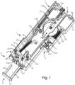
- the door-lock system essentially comprises a door-lock device 1, of the modular type, and a hooking or engaging member 2, which can be fixed to a door of a household appliance, in particular an oven (not shown in the figures), and which can be removably coupled to the door lock device 1.
- said engaging member 2 has a plate 21, for fixing to the door of the oven or of the household appliance in general, a prong 22, fixed to said plate 21, and a security member 23, also fixed to said plate 21, which operation will be better defined below.
- Said security member 23 has the shape of a bar and is arranged substantially parallel to the prong 22.
- the door-lock device 1 comprises a containment casing 3 for housing the components of the door-lock device 1, and a blocking group 4, intended to engage and hold the hook 2 of said oven door.
- the door-lock device 1 comprises a closing detection unit 5, to detect the engagement state of the blocking group 4 with the prong 22 and, therefore, the closure of the door of the household appliance, a retrieving group 6, to return the household appliance door back to close, and a safety detection unit 7, to detect when the security member 23 is engaged with the door-lock device 1 and, therefore, the household appliance door is closed.
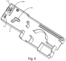
- the containment casing 3 comprises a base 31, to contain the components of the door lock 1, and a lid 32, arranged on said base 31 to close the containment casing 3.
- said base 31 has on one side a first opening 311, into which the prong 22 of said hooking member 2 can be inserted, and a second opening 312, into which the security member 23 of said engaging member 2 can be inserted, as will be better explained below.
- the blocking group 4 comprises a rotating hook 41, configured to engage with the prong 22 when the latter is inserted into the opening 311, so as to rotate around a first pin 411 of said rotating hook 41.
- the prong 22 has an opening 221, in which a portion of said rotating hook 41 can be inserted in such a way as to allow, as mentioned, the rotating hook 41, when in use, to engage with said prong 22.
- Said rotating hook 41 also comprises a second free pin 412, the operation of which will be better explained below.
- said blocking group 4 also comprises a support and guide element 42 comprising an "L"-shaped guide, fixed to said base 31 of said containment casing 3.
- the second free pin 412 is constrained to said "L"-shaped guide of said support and guide element 42 in such a way as to allow said rotating hook 41 to pass from a first position or rest or disengagement position to an operating position, in which it is engaged with the prong.
- said rotating hook 41 passes from the rest position to the operating position by means of an intermediate positioning, in which the rotating hook 41 is engaged but not locked with the prong 22, when the latter is inserted into opening 311.
- the blocking group 4 comprises a lever 43 having one end connected, by means of the first pin 411, to said rotating hook 41 and the other end fixed to the base 31 of the containment casing 3 by means of a fourth pin 414.
- the lever 43 comprises a pair of openings 43A, 43B at one end, and a further pair of openings 43C, 43D at the other end.
- the openings 43A, 43B are arranged in such a way as to allow the insertion of said first pin 411, while the openings 43C, 43D are arranged in such a way as to allow the insertion of said fourth pin 414.
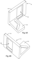
- the blocking unit 4 comprises a blocking member 44, arranged in proximity to the second opening 312 of said base 31 and connected to said rotating hook 41, as will be better explained hereinafter.
- this blocking member 44 is a bulkhead or sliding wall.
- the blocking member 44 can be different from said bulkhead or sliding wall without thereby departing from the scope of protection of the present invention.
- the blocking member 44 comprises a first portion 441 having an opening 442, and a second portion 443, fixed to said first portion 441 and comprising a guide for said rotating hook 41.
- the rotating hook 41 comprises a third free pin 413 arranged constrained to said guide of said second portion 443, so that, when said rotating hook 41 is in the rest position or in the intermediate position, the blocking member 44 assumes a closing position, in which the first portion 441 at least partially obstructs the insertion of said security member 23 into the second opening 312, and, when the rotating hook 41 is in the operative position, the blocking member 44 assumes an opening position, in which the first portion 441 allows the insertion of said security member 23 into the second opening 312.
- the movement of said blocking member 44 is synchronized with the movement of the rotating hook 41, so that only when the rotating hook 41 is engaged and locked with the prong 22, the blocking member 44 "discovers" the opening 312, also allowing the insertion of the security member 23 in the door-lock device 1.
- Said blocking group 4 also comprises a sliding guide 444, fixed to said base 31 of said containment casing 3.
- the first portion 441 is constrained to slide along said sliding guide 444 in such a way as to allow said blocking member 44 to pass from the closed position to the open position when, respectively, the rotating hook 41 passes from the rest position to the operating position.
- the second opening 312 of said base 31 and the opening 442 of said first portion 441 are not overlapped on each other, not allowing the insertion of the security member 23 through the second opening 312. In fact, in this case the second opening 312 is obstructed or blocked by the first portion 441 of said blocking member 44.
- the blocking member 44 When, on the other hand, the blocking member 44 is in the open position, the second opening 312 of said base 31 and the opening 442 of said first portion 441 are at least partially overlapped on each other, allowing the insertion of said security member 23 through the second opening 312 and then through the opening 442.
- the overlap between the second opening 312 and the opening 442 is a total overlap.
- the overlap between the second opening 312 and the opening 442 can be also partial.
- the blocking group 4 comprises a spring 45, having one end connected to said base 31, and the other end fixed to the lever 43.
- the operation of said spring 45 will be better explained below.
- the retrieving group 6 comprises a slider 61, a toothed wheel 62, engaged with said slider 61, and a first rod 611, the free end of which is located in proximity to said rotating hook 41, and the operation of which will be better explained below.
- said retrieving group 6 also comprises a lead screw 63 engaged with said toothed wheel 62 and an electric motor 64, the shaft of which is keyed with said lead screw 63.
- the closing detection unit 5 comprises a first microswitch 51, which interferes with said first rod 611 of said slider 61.
- the first microswitch 51 is capable of detecting the engagement or disengagement status of the rotating hook 41 with the prong 22 and, therefore, the closing or opening of the household appliance door respectively.
- the first microswitch 51 allows detecting the movement of said first rod 611 by means of a cam 510, which is able to act, in use, on the button of the microswitch 51 to change the state of the contacts (not shown in the figures). Therefore, said first microswitch 51 allows detecting the interference of said first rod 611 with said rotating hook 41.
- the safety detection unit 7 comprises a second microswitch 71A, a third microswitch 71B and a second rod 72 arranged, with respect to said first rod 611, on the opposite side of said base 31.
- the second 71A and the third 71B microswitches are capable of detecting when the security member 23 is engaged or disengaged with the door-lock device 1.
- the second 71A and the third 71B microswitches allow detecting the movement of said second rod 72 by means of a cam 710 and a further cam 711, which are able to act, in use, on the buttons of the respective microswitch 71A, 71B to change the status of the contacts (not shown in the figures). Therefore, the secondo 71A and the third 71B microswitches allow detecting the interference of said second rod 72 with said rotating hook 41 with said security member 23.
- figure 9 shows a second embodiment of the door-lock system S according to the present invention, in which the door-lock device 1 is without the closing detection unit 5 and the retrieving group 6.
- Figure 10 shows a third embodiment of the door-lock system S according to the present invention, in which the engaging member 2 is without the security member 23 and the door-lock device 1 is without the security detection unit 7.
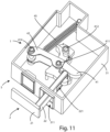
- Figure 11 shows a fourth embodiment of the door-lock system S according to the present invention, in which the engaging member 2 is without the security member 23 and the door-lock device 1 is without the locking detection unit 5, safety detection unit 7 as well as retrieving group 6.
- Figures 12 and 13 show a fifth embodiment of the door-lock system S according to the present invention, in which the door-lock device 1 has no retrieving group 6 and comprises a further blocking group 8.
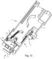
- Figures 14 and 15 show a sixth embodiment of the door-lock system S, in which the engaging member 2 has no security member 23 and the door-lock device 1 has no detection unit 5. locking and call group 6 and includes the further blocking group 8.
- Figure 16 shows a seventh embodiment of the door-lock system S, in which the door-lock device 1 has a base 31 having a compact structure.
- Figure 17 shows an eighth embodiment of the lock-door system S.
- the security member 23 enters said second opening 312 and interferes with said second rod 72.
- the rotating hook 41 is in the operative position and the prong 22 is engaged and held by the rotating hook 41.
- said electric motor 64 When, on the other hand, in the door opening condition, said electric motor 64 is activated manually or automatically, the lead screw 63 rotates, causing in turn the rotation of the toothed wheel 62. This allows the slider 61 to move along the direction A, towards said rotating hook 41.
- the slider 61 pushes the first rod 611, the free end of which interferes with the rotating hook 41 causing the latter to rotate with respect to said first pin 411 and, therefore, the sliding of said second free pin 412 on said guide of said support and guide element 42, in the opposite direction with respect to what happens during the closing step of the door.
- the movement of the rotating hook 41 causes the expansion of the spring 45 and the sliding of the third free pin 413 on said guide of said second portion 443 and, therefore, the passage of said blocking member 44 from the open position to the closed position, by sliding the first portion 441 along the sliding guide 444, preventing the security member 23 from being inserted through the second opening 312.
- An advantage of the door-lock system according to the present invention is that of signaling, by means of the same device, the status of the door of the household appliance, the lock of the same door or the activation/deactivation of the appliance.
- a further advantage of the door-lock system according to the present invention is that of providing the movable bulkhead synchronized with the movement of the rotating hook, so as to allow the insertion of the security member only when the rotating hook is engaged with the prong of the household appliance.
Landscapes
- Engineering & Computer Science (AREA)
- Mechanical Engineering (AREA)
- Chemical & Material Sciences (AREA)
- Combustion & Propulsion (AREA)
- General Engineering & Computer Science (AREA)
- Structural Engineering (AREA)
- Control Of Vending Devices And Auxiliary Devices For Vending Devices (AREA)
- Lock And Its Accessories (AREA)
Claims (12)
- Système de verrouillage de porte (S) pour un appareil ménager, dans lequel ledit appareil ménager est du type comprenant un cadre et une porte articulée sur ledit cadre, et dans lequel ledit système de verrouillage de porte (S) comprend: un élément d'engagement (2), pouvant être fixé à ladite porte de l'appareil ménager, et comprenant une tige (22) et un élément de sécurité (23) disposé sensiblement parallèlement à ladite tige (22); et un dispositif de verrouillage de porte (1), comprenant un boîtier de confinement (3) pouvant être fixé au châssis de l'appareil ménager, un groupe de blocage (4), destiné à s'engager dans ledit élément d'engagement (2) et à le maintenir, qui comprend à son tour: un crochet rotatif (41), disposé à l'intérieur de ladite enveloppe de confinement (3), et capable de passer d'une position de repos, dans laquelle la tige (22) n'est pas engagée avec ledit crochet rotatif (41), à une position de fonctionnement, dans laquelle la tige (22) est engagée et bloquée avec ledit crochet rotatif (41), de manière à maintenir ladite porte fermée; un élément de blocage (44), associé audit crochet rotatif (41), tel que, lorsque ledit crochet rotatif (41) est dans ladite position de repos, ledit élément de blocage (44) est adapté pour prendre une position de fermeture, empêchant l'insertion dudit élément de sécurité (23) dans ledit dispositif de verrouillage de porte (1), et que, lorsque ledit crochet rotatif (41) est dans ladite position de fonctionnement, ledit élément de blocage (44) prend une position d'ouverture, permettant l'insertion dudit élément de sécurité (23) dans ledit dispositif de verrouillage de porte (1); et une unité de détection de sécurité (7), configurée pour interagir avec ledit élément de sécurité (23), de manière à détecter quand ledit élément de sécurité (23) est engagé ou désengagé dudit dispositif de verrouillage de porte (1); dans lequel ledit boîtier de confinement (3) comprend une base (31) et un couvercle (32), disposé sur ladite base (31), pour fermer ledit boîtier de confinement (3), dans lequel ladite base (31) a une première ouverture (311) et une seconde ouverture (312) disposée à côté de ladite première ouverture (311), dans laquelle ladite tige (22) peut être insérée dans ladite première ouverture (311), et ledit élément de sécurité (23) peut être inséré dans ladite seconde ouverture (312), et dans lequel ledit élément de blocage (44) est disposé à proximité de ladite seconde ouverture (312) et est relié audit crochet rotatif (41); caractérisé par le fait que ledit système de verrouillage de porte (S) comprend un guide coulissant (444), fixé à ladite base (31) de ladite enceinte de confinement (3), dans lequel ledit élément de blocage (44) comprend une première partie (441) ayant une ouverture (442), et une deuxième partie (443), fixée à ladite première partie (441) et comprenant un guide pour ledit crochet rotatif (41), et dans lequel ladite première partie (441) est contrainte de glisser le long dudit guide coulissant (444) de sorte que, lorsque ledit élément de blocage (44) est dans ladite position de fermeture, ladite seconde ouverture (312) et ladite ouverture (442) ne se chevauchent pas, empêchant l'insertion de l'élément de sécurité (23) à travers la seconde ouverture (312), et que, lorsque ledit élément de blocage (44) est dans ladite position d'ouverture, ladite seconde ouverture (312) et ladite ouverture (442) se chevauchent au moins partiellement, permettant l'insertion dudit élément de sécurité (23) à travers la seconde ouverture (312) et ladite ouverture (442); et dans lequel ledit crochet rotatif (41) comprend une troisième goupille libre (413) contrainte sur ledit guide de ladite deuxième partie (443) de sorte que, lorsque ledit crochet rotatif (41) est dans ladite position de repos, ledit élément de blocage (44) prend une position de fermeture, et que, lorsque ledit crochet rotatif (41) est dans ladite position de rotation, ledit élément de blocage (44) prend une position d'ouverture.
- Système de verrouillage de porte (S) selon la revendication précédente, caractérisé en ce que l'unité de détection de sécurité (7) comprend un deuxième microcontact (71A) et un troisième microcontact (71B), ainsi qu'une deuxième tige (72) disposée sur un côté de la base (31), dans lequel chacun de ces deuxième (71A) et troisième (71B) micro-interrupteurs est configuré pour détecter si l'élément de sécurité (23) interfère ou n'interfère pas avec la deuxième tige (72).
- Système de verrouillage de porte (S) selon l'une quelconque des revendications précédentes, caractérisé en ce qu'il comprend une unité de détection de fermeture (5) comportant un premier microinterrupteur (51) configuré pour détecter si ledit crochet rotatif (41) est engagé ou désengagé avec ladite cheville (22).
- Système de verrouillage de porte (S) selon l'une quelconque des revendications précédentes, caractérisé en ce que ledit groupe de blocage (4) comprend un élément de support et de guidage (42) comprenant un guide fixé sur ledit (31) de ladite enveloppe de confinement (3), dans lequel ledit crochet rotatif (41) comprend un second axe libre (412) contraint à l'élément de support et de guidage (42) de manière à permettre au crochet rotatif (41) de passer de ladite position de repos à ladite position de fonctionnement.
- Système de verrouillage de porte (S) selon l'une quelconque des revendications précédentes, caractérisé en ce que ledit crochet rotatif (41) comprend un premier axe (411) autour duquel ledit crochet rotatif (41) est apte à tourner, et en ce que ledit groupe de blocage (4) comprend un quatrième axe (414), et un levier (43) ayant une extrémité reliée, au moyen de ladite première goupille (411), audit crochet rotatif (41) et une autre extrémité fixée, au moyen de ladite quatrième goupille (414), à ladite base (31) de ladite enceinte de confinement (3).
- Système de verrouillage de porte (S) selon l'une quelconque des revendications précédentes, caractérisé en ce qu'il comprend un groupe de récupération (6) pour récupérer ladite porte dudit appareil ménager à la fermeture, dans lequel ledit groupe de récupération (6) comprend un coulisseau (61), une roue dentée (62), engagée avec ledit coulisseau (61), une vis sans fin (63) engagée avec ladite roue dentée (62), et un moteur électrique (64), dont l'arbre est couplé à ladite vis mère (63), de sorte que, lorsqu'il est utilisé, ledit moteur électrique (64) entraîne la rotation de ladite vis mère (63) et, par conséquent, de ladite roue dentée (62), de sorte que ledit coulisseau (61) est déplacé le long d'une direction A.
- Système de verrouillage de porte (S) selon la revendication précédente, caractérisé en ce que ledit groupe de récupération (6) comprend une première tige (611), dont l'extrémité libre est à proximité dudit crochet rotatif (41), dans lequel ladite première tige (611) est mobile selon ladite direction A.
- Système de verrouillage de porte (S) selon l'une quelconque des revendications précédentes, caractérisé en ce que ledit élément d'engagement (2) comprend une plaque (21) pour fixer ledit élément d'engagement (2) à ladite porte dudit appareil ménager, dans lequel ladite tige (22) est fixée à ladite plaque (21) et ledit élément de sécurité (23), également fixé à ladite plaque (21), a la forme d'une barre et est disposé sensiblement parallèlement à ladite tige (22).
- Système de verrouillage de porte (S) selon l'une quelconque des revendications précédentes, caractérisé en ce que ledit élément de blocage (44) est une paroi coulissante.
- Four comprenant un cadre dans lequel est définie une chambre de cuisson, une porte articulée sur ledit cadre pour fermer ladite chambre de cuisson, et un système de verrouillage de porte (S) selon l'une quelconque des revendications 1 à 9, dans lequel ledit élément d'engagement (2) est fixé à ladite porte, et dans lequel ledit dispositif de verrouillage de porte (1) est couplé de manière amovible avec ledit élément d'engagement (2).
- Four selon la revendication précédente, caractérisé en ce que ledit système de verrouillage de porte (S) est disposé dans la partie inférieure ou supérieure de ladite porte.
- Four selon l'une quelconque des revendications 10 ou 11, caractérisé en ce qu'il comprend un système de verrouillage de porte (S) disposé dans ladite partie inférieure de ladite porte et un système de verrouillage de porte (S) disposé dans ladite partie supérieure de ladite porte.
Applications Claiming Priority (1)
| Application Number | Priority Date | Filing Date | Title |
|---|---|---|---|
| IT102020000026906A IT202000026906A1 (it) | 2020-11-11 | 2020-11-11 | Sistema blocco-porta modulare. |
Publications (3)
| Publication Number | Publication Date |
|---|---|
| EP4001771A1 EP4001771A1 (fr) | 2022-05-25 |
| EP4001771B1 true EP4001771B1 (fr) | 2025-01-08 |
| EP4001771C0 EP4001771C0 (fr) | 2025-01-08 |
Family
ID=74347588
Family Applications (1)
| Application Number | Title | Priority Date | Filing Date |
|---|---|---|---|
| EP21206107.1A Active EP4001771B1 (fr) | 2020-11-11 | 2021-11-03 | Système de verrouillage de porte modulaire |
Country Status (3)
| Country | Link |
|---|---|
| US (1) | US11988020B2 (fr) |
| EP (1) | EP4001771B1 (fr) |
| IT (1) | IT202000026906A1 (fr) |
Families Citing this family (3)
| Publication number | Priority date | Publication date | Assignee | Title |
|---|---|---|---|---|
| DE102022116999B4 (de) * | 2022-07-07 | 2024-02-15 | Emz-Hanauer Gmbh & Co. Kgaa | Türverschluss mit Selbstheilung |
| KR102765526B1 (ko) * | 2023-03-13 | 2025-02-11 | 두얼파워전자(주) | 가전제품 오토오픈 도어락 장치 |
| DE102023135158A1 (de) * | 2023-12-14 | 2025-06-18 | Maco Technologie Gmbh | Verschluss |
Citations (2)
| Publication number | Priority date | Publication date | Assignee | Title |
|---|---|---|---|---|
| EP0288811A2 (fr) * | 1987-04-27 | 1988-11-02 | Litton Systems, Inc. | Support pour interrupteur d'interverrouillage |
| CN105916228A (zh) * | 2016-06-12 | 2016-08-31 | 广东美的厨房电器制造有限公司 | 联锁开关的锁体及微波炉 |
Family Cites Families (19)
| Publication number | Priority date | Publication date | Assignee | Title |
|---|---|---|---|---|
| JPS57129329A (en) * | 1981-02-02 | 1982-08-11 | Matsushita Electric Ind Co Ltd | High-frequency heating device |
| US4516007A (en) * | 1982-08-19 | 1985-05-07 | Litton Systems, Inc. | Interlock switch module for a microwave oven |
| US4529852A (en) * | 1983-07-12 | 1985-07-16 | Cherry Electrical Products Corporation | Electrical appliance interlock switch |
| US4663505A (en) * | 1986-05-22 | 1987-05-05 | Litton Systems, Inc. | Interlock switch base plate assembly |
| GB2278394B (en) * | 1993-04-27 | 1996-04-10 | Seal | Locks |
| US5672857A (en) * | 1996-04-26 | 1997-09-30 | Honeywell Inc. | Switch actuating mechanism for two sequentially activated switches |
| KR100272367B1 (ko) * | 1997-11-15 | 2000-11-15 | 구자홍 | 전자레인지의 도어 개폐구조 |
| US6397646B1 (en) * | 2000-11-30 | 2002-06-04 | Shing-Hwa Doong | Door lock |
| DE50014457D1 (de) * | 2000-12-01 | 2007-08-16 | Emz Hanauer Gmbh & Co Kgaa | Türverriegelung |
| DE10154850C1 (de) * | 2001-11-08 | 2003-06-18 | Ellenberger & Poensgen | Türverriegelung |
| US7032939B2 (en) * | 2003-05-08 | 2006-04-25 | Southco, Inc. | Lock |
| GB2439324B (en) * | 2006-06-22 | 2011-12-28 | Panasonic Mfg Uk Ltd | Domestic appliance with controlled door opening |
| GB2455783B (en) * | 2007-12-21 | 2012-07-18 | Panasonic Mfg Uk Ltd | Controlled door opening in domestic appliances |
| EP2141311B1 (fr) * | 2008-07-02 | 2012-12-05 | Ojmar S.A. | Module de blocage électronique pour systèmes de fermeture |
| EP2141664B1 (fr) * | 2008-07-02 | 2012-03-14 | Ojmar S.A. | Verrouillage électronique programmable |
| DE102013104495A1 (de) * | 2013-05-02 | 2014-11-06 | Keba Ag | Schloss mit einer Sicherheitsvorrichtung für einen Aufbewahrungsautomaten, sowie Aufbewahrungsautomat |
| DE102016008317B4 (de) * | 2016-07-07 | 2018-10-31 | Emz-Hanauer Gmbh & Co. Kgaa | Türverschluss für ein elektrisches Haushaltsgerät |
| CN107687292B (zh) * | 2016-08-03 | 2020-10-27 | 山东新北洋信息技术股份有限公司 | 电子锁控制方法及控制装置 |
| KR20220002377A (ko) * | 2019-04-19 | 2022-01-06 | 엘레트로테크니카 롤드 에스.알.엘. | 도어 특히 세탁물 처리용 가전제품의 도어를 개폐하는 장치 |
-
2020
- 2020-11-11 IT IT102020000026906A patent/IT202000026906A1/it unknown
-
2021
- 2021-11-03 EP EP21206107.1A patent/EP4001771B1/fr active Active
- 2021-11-09 US US17/454,062 patent/US11988020B2/en active Active
Patent Citations (2)
| Publication number | Priority date | Publication date | Assignee | Title |
|---|---|---|---|---|
| EP0288811A2 (fr) * | 1987-04-27 | 1988-11-02 | Litton Systems, Inc. | Support pour interrupteur d'interverrouillage |
| CN105916228A (zh) * | 2016-06-12 | 2016-08-31 | 广东美的厨房电器制造有限公司 | 联锁开关的锁体及微波炉 |
Also Published As
| Publication number | Publication date |
|---|---|
| US20220145665A1 (en) | 2022-05-12 |
| US11988020B2 (en) | 2024-05-21 |
| EP4001771A1 (fr) | 2022-05-25 |
| EP4001771C0 (fr) | 2025-01-08 |
| IT202000026906A1 (it) | 2022-05-11 |
Similar Documents
| Publication | Publication Date | Title |
|---|---|---|
| EP4001771B1 (fr) | Système de verrouillage de porte modulaire | |
| US4088354A (en) | Door locking mechanism for self-cleaning oven | |
| US11578508B2 (en) | Door-locking device with safety system | |
| US9587837B2 (en) | Door lock device | |
| EP1975300B1 (fr) | Dispositif de verrouillage pour la fermeture du couvercle de machines à laver | |
| EP3091153B1 (fr) | Dispositif de verrouillage pour une porte d'un appareil ménager | |
| US20100117378A1 (en) | Doorlock device for an electric home appliance | |
| NZ501925A (en) | Locking and unlocking device for door of domestic electrical appliance such a washing machine with electrically controlled actuator causing toothed wheel to rotate | |
| KR20090115018A (ko) | 의류처리장치의 도어스위치어셈블리 | |
| EP3717687B1 (fr) | Verrou de porte pour appareils électroménagers | |
| CN101137870A (zh) | 热解炉门的闭锁装置 | |
| KR100963390B1 (ko) | 도어 래치 어셈블리 및 이를 포함하는 조리기기 | |
| EP3935246B1 (fr) | Dispositif de verrouillage de porte réinitialisable pour appareil électroménager, en particulier un lave-vaisselle, et appareil électroménager équipé de celui-ci | |
| EP2977498B1 (fr) | Procédé d'ouverture d'urgence d'un dispositif de verrouillage de porte d'un lave-linge et/ou appareil de séchage | |
| EP4007870B1 (fr) | Hotte verticale | |
| EP2726663B1 (fr) | Dispositif de verrouillage et déverrouillage de la porte d'un appareil électroménager | |
| WO2020180564A1 (fr) | Dispositif de verrouillage de porte réinitialisable pour appareil électroménager, en particulier un lave-vaisselle, et appareil électroménager équipé de celui-ci | |
| EP3714093B1 (fr) | Dispositif de fermeture et d'ouverture de panneaux, en particulier de panneaux d'appareils électroménagers tels que des machines à laver et similaires | |
| KR102834965B1 (ko) | 오토 오픈 도어락 장치 | |
| KR102834967B1 (ko) | 푸시 타입 오토 오픈 도어락 장치 | |
| US20260085548A1 (en) | Auto-open door lock device | |
| KR20250166662A (ko) | 도어 잠금 시스템 및 이를 포함하는 조리기기 | |
| KR102767616B1 (ko) | 푸시 도어락 장치 | |
| EP3309287B1 (fr) | Machine à laver et/ou sécher le linge à chargement par le haut avec mécanisme de sécurité | |
| KR101481588B1 (ko) | 의류처리장치의 도어스위치어셈블리 |
Legal Events
| Date | Code | Title | Description |
|---|---|---|---|
| PUAI | Public reference made under article 153(3) epc to a published international application that has entered the european phase |
Free format text: ORIGINAL CODE: 0009012 |
|
| STAA | Information on the status of an ep patent application or granted ep patent |
Free format text: STATUS: THE APPLICATION HAS BEEN PUBLISHED |
|
| AK | Designated contracting states |
Kind code of ref document: A1 Designated state(s): AL AT BE BG CH CY CZ DE DK EE ES FI FR GB GR HR HU IE IS IT LI LT LU LV MC MK MT NL NO PL PT RO RS SE SI SK SM TR |
|
| STAA | Information on the status of an ep patent application or granted ep patent |
Free format text: STATUS: REQUEST FOR EXAMINATION WAS MADE |
|
| 17P | Request for examination filed |
Effective date: 20221121 |
|
| RBV | Designated contracting states (corrected) |
Designated state(s): AL AT BE BG CH CY CZ DE DK EE ES FI FR GB GR HR HU IE IS IT LI LT LU LV MC MK MT NL NO PL PT RO RS SE SI SK SM TR |
|
| STAA | Information on the status of an ep patent application or granted ep patent |
Free format text: STATUS: EXAMINATION IS IN PROGRESS |
|
| RAP1 | Party data changed (applicant data changed or rights of an application transferred) |
Owner name: ELBI INTERNATIONAL S.P.A. |
|
| 17Q | First examination report despatched |
Effective date: 20240327 |
|
| GRAP | Despatch of communication of intention to grant a patent |
Free format text: ORIGINAL CODE: EPIDOSNIGR1 |
|
| STAA | Information on the status of an ep patent application or granted ep patent |
Free format text: STATUS: GRANT OF PATENT IS INTENDED |
|
| RIC1 | Information provided on ipc code assigned before grant |
Ipc: A47L 15/42 20060101ALN20240902BHEP Ipc: E05B 47/00 20060101ALI20240902BHEP Ipc: D06F 39/14 20060101ALI20240902BHEP Ipc: E05C 3/24 20060101ALI20240902BHEP Ipc: E05B 63/00 20060101ALI20240902BHEP Ipc: E05C 19/02 20060101ALI20240902BHEP Ipc: E05B 17/00 20060101ALI20240902BHEP Ipc: F24C 15/02 20060101AFI20240902BHEP |
|
| INTG | Intention to grant announced |
Effective date: 20240920 |
|
| GRAS | Grant fee paid |
Free format text: ORIGINAL CODE: EPIDOSNIGR3 |
|
| GRAA | (expected) grant |
Free format text: ORIGINAL CODE: 0009210 |
|
| STAA | Information on the status of an ep patent application or granted ep patent |
Free format text: STATUS: THE PATENT HAS BEEN GRANTED |
|
| RAP3 | Party data changed (applicant data changed or rights of an application transferred) |
Owner name: ELBI INTERNATIONAL S.P.A. |
|
| AK | Designated contracting states |
Kind code of ref document: B1 Designated state(s): AL AT BE BG CH CY CZ DE DK EE ES FI FR GB GR HR HU IE IS IT LI LT LU LV MC MK MT NL NO PL PT RO RS SE SI SK SM TR |
|
| REG | Reference to a national code |
Ref country code: GB Ref legal event code: FG4D |
|
| REG | Reference to a national code |
Ref country code: CH Ref legal event code: EP |
|
| REG | Reference to a national code |
Ref country code: DE Ref legal event code: R096 Ref document number: 602021024605 Country of ref document: DE |
|
| REG | Reference to a national code |
Ref country code: IE Ref legal event code: FG4D |
|
| U01 | Request for unitary effect filed |
Effective date: 20250128 |
|
| U07 | Unitary effect registered |
Designated state(s): AT BE BG DE DK EE FI FR IT LT LU LV MT NL PT RO SE SI Effective date: 20250203 |
|
| PG25 | Lapsed in a contracting state [announced via postgrant information from national office to epo] |
Ref country code: RS Free format text: LAPSE BECAUSE OF FAILURE TO SUBMIT A TRANSLATION OF THE DESCRIPTION OR TO PAY THE FEE WITHIN THE PRESCRIBED TIME-LIMIT Effective date: 20250408 |
|
| PG25 | Lapsed in a contracting state [announced via postgrant information from national office to epo] |
Ref country code: PL Free format text: LAPSE BECAUSE OF FAILURE TO SUBMIT A TRANSLATION OF THE DESCRIPTION OR TO PAY THE FEE WITHIN THE PRESCRIBED TIME-LIMIT Effective date: 20250108 |
|
| PG25 | Lapsed in a contracting state [announced via postgrant information from national office to epo] |
Ref country code: ES Free format text: LAPSE BECAUSE OF FAILURE TO SUBMIT A TRANSLATION OF THE DESCRIPTION OR TO PAY THE FEE WITHIN THE PRESCRIBED TIME-LIMIT Effective date: 20250108 |
|
| PG25 | Lapsed in a contracting state [announced via postgrant information from national office to epo] |
Ref country code: NO Free format text: LAPSE BECAUSE OF FAILURE TO SUBMIT A TRANSLATION OF THE DESCRIPTION OR TO PAY THE FEE WITHIN THE PRESCRIBED TIME-LIMIT Effective date: 20250408 Ref country code: IS Free format text: LAPSE BECAUSE OF FAILURE TO SUBMIT A TRANSLATION OF THE DESCRIPTION OR TO PAY THE FEE WITHIN THE PRESCRIBED TIME-LIMIT Effective date: 20250508 |
|
| PG25 | Lapsed in a contracting state [announced via postgrant information from national office to epo] |
Ref country code: HR Free format text: LAPSE BECAUSE OF FAILURE TO SUBMIT A TRANSLATION OF THE DESCRIPTION OR TO PAY THE FEE WITHIN THE PRESCRIBED TIME-LIMIT Effective date: 20250108 |
|
| PG25 | Lapsed in a contracting state [announced via postgrant information from national office to epo] |
Ref country code: GR Free format text: LAPSE BECAUSE OF FAILURE TO SUBMIT A TRANSLATION OF THE DESCRIPTION OR TO PAY THE FEE WITHIN THE PRESCRIBED TIME-LIMIT Effective date: 20250409 |
|
| PG25 | Lapsed in a contracting state [announced via postgrant information from national office to epo] |
Ref country code: SM Free format text: LAPSE BECAUSE OF FAILURE TO SUBMIT A TRANSLATION OF THE DESCRIPTION OR TO PAY THE FEE WITHIN THE PRESCRIBED TIME-LIMIT Effective date: 20250108 |
|
| U20 | Renewal fee for the european patent with unitary effect paid |
Year of fee payment: 5 Effective date: 20250902 |
|
| PG25 | Lapsed in a contracting state [announced via postgrant information from national office to epo] |
Ref country code: CZ Free format text: LAPSE BECAUSE OF FAILURE TO SUBMIT A TRANSLATION OF THE DESCRIPTION OR TO PAY THE FEE WITHIN THE PRESCRIBED TIME-LIMIT Effective date: 20250108 |
|
| PG25 | Lapsed in a contracting state [announced via postgrant information from national office to epo] |
Ref country code: SK Free format text: LAPSE BECAUSE OF FAILURE TO SUBMIT A TRANSLATION OF THE DESCRIPTION OR TO PAY THE FEE WITHIN THE PRESCRIBED TIME-LIMIT Effective date: 20250108 |
|
| PLBE | No opposition filed within time limit |
Free format text: ORIGINAL CODE: 0009261 |
|
| STAA | Information on the status of an ep patent application or granted ep patent |
Free format text: STATUS: NO OPPOSITION FILED WITHIN TIME LIMIT |
|
| 26N | No opposition filed |
Effective date: 20251009 |