EP4001777B1 - Séparateur hydraulique pour un système thermique - Google Patents
Séparateur hydraulique pour un système thermique Download PDFInfo
- Publication number
- EP4001777B1 EP4001777B1 EP21209373.6A EP21209373A EP4001777B1 EP 4001777 B1 EP4001777 B1 EP 4001777B1 EP 21209373 A EP21209373 A EP 21209373A EP 4001777 B1 EP4001777 B1 EP 4001777B1
- Authority
- EP
- European Patent Office
- Prior art keywords
- connection
- separator
- sleeve
- inner chamber
- circuit
- Prior art date
- Legal status (The legal status is an assumption and is not a legal conclusion. Google has not performed a legal analysis and makes no representation as to the accuracy of the status listed.)
- Active
Links
Images


Classifications
-
- F—MECHANICAL ENGINEERING; LIGHTING; HEATING; WEAPONS; BLASTING
- F24—HEATING; RANGES; VENTILATING
- F24D—DOMESTIC- OR SPACE-HEATING SYSTEMS, e.g. CENTRAL HEATING SYSTEMS; DOMESTIC HOT-WATER SUPPLY SYSTEMS; ELEMENTS OR COMPONENTS THEREFOR
- F24D19/00—Details
- F24D19/0092—Devices for preventing or removing corrosion, slime or scale
-
- B—PERFORMING OPERATIONS; TRANSPORTING
- B01—PHYSICAL OR CHEMICAL PROCESSES OR APPARATUS IN GENERAL
- B01D—SEPARATION
- B01D29/00—Filters with filtering elements stationary during filtration, e.g. pressure or suction filters, not covered by groups B01D24/00 - B01D27/00; Filtering elements therefor
- B01D29/11—Filters with filtering elements stationary during filtration, e.g. pressure or suction filters, not covered by groups B01D24/00 - B01D27/00; Filtering elements therefor with bag, cage, hose, tube, sleeve or like filtering elements
- B01D29/13—Supported filter elements
- B01D29/23—Supported filter elements arranged for outward flow filtration
-
- B—PERFORMING OPERATIONS; TRANSPORTING
- B01—PHYSICAL OR CHEMICAL PROCESSES OR APPARATUS IN GENERAL
- B01D—SEPARATION
- B01D35/00—Filtering devices having features not specifically covered by groups B01D24/00 - B01D33/00, or for applications not specifically covered by groups B01D24/00 - B01D33/00; Auxiliary devices for filtration; Filter housing constructions
- B01D35/06—Filters making use of electricity or magnetism
-
- B—PERFORMING OPERATIONS; TRANSPORTING
- B01—PHYSICAL OR CHEMICAL PROCESSES OR APPARATUS IN GENERAL
- B01D—SEPARATION
- B01D35/00—Filtering devices having features not specifically covered by groups B01D24/00 - B01D33/00, or for applications not specifically covered by groups B01D24/00 - B01D33/00; Auxiliary devices for filtration; Filter housing constructions
- B01D35/14—Safety devices specially adapted for filtration; Devices for indicating clogging
- B01D35/153—Anti-leakage or anti-return valves
-
- B—PERFORMING OPERATIONS; TRANSPORTING
- B01—PHYSICAL OR CHEMICAL PROCESSES OR APPARATUS IN GENERAL
- B01D—SEPARATION
- B01D36/00—Filter circuits or combinations of filters with other separating devices
- B01D36/001—Filters in combination with devices for the removal of gas, air purge systems
-
- B—PERFORMING OPERATIONS; TRANSPORTING
- B03—SEPARATION OF SOLID MATERIALS USING LIQUIDS OR USING PNEUMATIC TABLES OR JIGS; MAGNETIC OR ELECTROSTATIC SEPARATION OF SOLID MATERIALS FROM SOLID MATERIALS OR FLUIDS; SEPARATION BY HIGH-VOLTAGE ELECTRIC FIELDS
- B03C—MAGNETIC OR ELECTROSTATIC SEPARATION OF SOLID MATERIALS FROM SOLID MATERIALS OR FLUIDS; SEPARATION BY HIGH-VOLTAGE ELECTRIC FIELDS
- B03C1/00—Magnetic separation
- B03C1/02—Magnetic separation acting directly on the substance being separated
- B03C1/025—High gradient magnetic separators
- B03C1/031—Component parts; Auxiliary operations
- B03C1/033—Component parts; Auxiliary operations characterised by the magnetic circuit
- B03C1/0332—Component parts; Auxiliary operations characterised by the magnetic circuit using permanent magnets
-
- B—PERFORMING OPERATIONS; TRANSPORTING
- B03—SEPARATION OF SOLID MATERIALS USING LIQUIDS OR USING PNEUMATIC TABLES OR JIGS; MAGNETIC OR ELECTROSTATIC SEPARATION OF SOLID MATERIALS FROM SOLID MATERIALS OR FLUIDS; SEPARATION BY HIGH-VOLTAGE ELECTRIC FIELDS
- B03C—MAGNETIC OR ELECTROSTATIC SEPARATION OF SOLID MATERIALS FROM SOLID MATERIALS OR FLUIDS; SEPARATION BY HIGH-VOLTAGE ELECTRIC FIELDS
- B03C1/00—Magnetic separation
- B03C1/02—Magnetic separation acting directly on the substance being separated
- B03C1/28—Magnetic plugs and dipsticks
- B03C1/284—Magnetic plugs and dipsticks with associated cleaning means, e.g. retractable non-magnetic sleeve
-
- B—PERFORMING OPERATIONS; TRANSPORTING
- B03—SEPARATION OF SOLID MATERIALS USING LIQUIDS OR USING PNEUMATIC TABLES OR JIGS; MAGNETIC OR ELECTROSTATIC SEPARATION OF SOLID MATERIALS FROM SOLID MATERIALS OR FLUIDS; SEPARATION BY HIGH-VOLTAGE ELECTRIC FIELDS
- B03C—MAGNETIC OR ELECTROSTATIC SEPARATION OF SOLID MATERIALS FROM SOLID MATERIALS OR FLUIDS; SEPARATION BY HIGH-VOLTAGE ELECTRIC FIELDS
- B03C1/00—Magnetic separation
- B03C1/02—Magnetic separation acting directly on the substance being separated
- B03C1/28—Magnetic plugs and dipsticks
- B03C1/286—Magnetic plugs and dipsticks disposed at the inner circumference of a recipient, e.g. magnetic drain bolt
-
- B—PERFORMING OPERATIONS; TRANSPORTING
- B03—SEPARATION OF SOLID MATERIALS USING LIQUIDS OR USING PNEUMATIC TABLES OR JIGS; MAGNETIC OR ELECTROSTATIC SEPARATION OF SOLID MATERIALS FROM SOLID MATERIALS OR FLUIDS; SEPARATION BY HIGH-VOLTAGE ELECTRIC FIELDS
- B03C—MAGNETIC OR ELECTROSTATIC SEPARATION OF SOLID MATERIALS FROM SOLID MATERIALS OR FLUIDS; SEPARATION BY HIGH-VOLTAGE ELECTRIC FIELDS
- B03C1/00—Magnetic separation
- B03C1/02—Magnetic separation acting directly on the substance being separated
- B03C1/30—Combinations with other devices, not otherwise provided for
-
- F—MECHANICAL ENGINEERING; LIGHTING; HEATING; WEAPONS; BLASTING
- F24—HEATING; RANGES; VENTILATING
- F24D—DOMESTIC- OR SPACE-HEATING SYSTEMS, e.g. CENTRAL HEATING SYSTEMS; DOMESTIC HOT-WATER SUPPLY SYSTEMS; ELEMENTS OR COMPONENTS THEREFOR
- F24D3/00—Hot-water central heating systems
- F24D3/10—Feed-line arrangements, e.g. providing for heat-accumulator tanks, expansion tanks ; Hydraulic components of a central heating system
- F24D3/1091—Mixing cylinders
-
- B—PERFORMING OPERATIONS; TRANSPORTING
- B03—SEPARATION OF SOLID MATERIALS USING LIQUIDS OR USING PNEUMATIC TABLES OR JIGS; MAGNETIC OR ELECTROSTATIC SEPARATION OF SOLID MATERIALS FROM SOLID MATERIALS OR FLUIDS; SEPARATION BY HIGH-VOLTAGE ELECTRIC FIELDS
- B03C—MAGNETIC OR ELECTROSTATIC SEPARATION OF SOLID MATERIALS FROM SOLID MATERIALS OR FLUIDS; SEPARATION BY HIGH-VOLTAGE ELECTRIC FIELDS
- B03C2201/00—Details of magnetic or electrostatic separation
- B03C2201/18—Magnetic separation whereby the particles are suspended in a liquid
-
- F—MECHANICAL ENGINEERING; LIGHTING; HEATING; WEAPONS; BLASTING
- F24—HEATING; RANGES; VENTILATING
- F24D—DOMESTIC- OR SPACE-HEATING SYSTEMS, e.g. CENTRAL HEATING SYSTEMS; DOMESTIC HOT-WATER SUPPLY SYSTEMS; ELEMENTS OR COMPONENTS THEREFOR
- F24D2220/00—Components of central heating installations excluding heat sources
- F24D2220/02—Fluid distribution means
- F24D2220/0221—Mixing cylinders
Definitions
- the invention relates to a separator filter for a thermal system, in particular a heating and/or cooling system.
- the creation of a node, in which there is a direct connection between the input lines of the primary circuit and of the secondary circuit, and the simultaneous use of a filter inside the separator, downstream of which there is the connection between the aforesaid node and the return line of the primary circuit, ensure a zero load loss between the aforesaid lines. Therefore, the separator always is in ideal operating conditions and ensures a perfect independence between the circuits in any condition.
- the invention also relates to a thermal system according to claim 14.
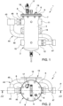
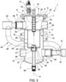
- the separator 1 comprises a hollow body 2 with a vertical axis A having a substantially cylindrical lateral wall 3 and a bottom wall 4, which preferably is bulged downwards.
- the body 2 comprises four threaded tubular sleeves 9, 10, 11, 12, which define respective connection openings communicating with the chamber 5 and are arranged two (9, 10) on one side of the lateral wall 3 and two (11, 12) on the opposite side ( figures 1 and 3 ).
- the axes of the sleeves 9, 10, 11, 12 are arranged on a common plane P ( figure 2 ) going through the axis A.
- the body 2 is finally provided with a bracket 13, which projects from the lateral wall 3 and ends with a plate 14, conveniently parallel to the plane P and elongated in a horizontal direction, which is provided with holes 15 for the fixing to a wall or another support structure.
- the cover 6 which is provided with an upper handle 16 to help it be moved, carries an air purge valve 17, which is connected to the chamber 5 by means of a ball shut-off valve 18.
- the cover 6 is further provided with a joint 19 for the possible introduction of substances into the carrier fluid.
- the cover 6 is mounted on the flange 7 of the body 2 with the interposition of a gasket 22.
- the lateral wall 3 defines, immediately under the sleeves 9, 11, an annular inner flange 24, which supports a filter 25.
- the filter 25 which is shaped like a cylindrical basket, comprises a lateral wall 26 made of a metal net with meshes with dimensions in the range of 100 um, a bottom wall 27 and an upper annular flange 28, which is designed to rest against the inner flange 24 of the wall 3 of the body 2.
- the filter 25 is provided with a pair of bars 29 ( figure 4 ), which are fixed on the inside of the lateral wall 26 in a diametrically opposite position relative to one another.
- the bars 29 axially project upwards and end with respective ends 30 bent in the form of an L, which can be grabbed in order to remove and install the filter 25.
- the bottom wall 27 of the filter 25 has a central through hole 34 ( figure 3 ) housing, in a sliding manner, a tubular sleeve 35, which projects downwards and engages a funnel-shaped upper end 36 of an axial duct 37, which leads outwards at the centre of the bottom wall 4; at the lower end 38 of the duct 37 there is housed a ball purge valve 39.
- the tubular sleeve 35 is provided, at the top, with a disc shutter 40, which is designed to seal the hole 34 of the bottom wall 27 when the filter 25 is removed from the body 2.
- the sleeve 35 and the shutter 40 define a normally open valve, which is designed to automatically close when the filter 25 is removed.
- the filter 25 divides the inner chamber 5 of the body 2 into an upper filtering zone 5a, which houses the magnet 20, and into a lower hydraulic separation zone 5b. Therefore, the integration of the filter 25 on the inside of the body 2 has the effect of definitely allowing the zone 5b to be free from impurities and of preventing it from determining a pressure drop between the sleeve 10 and the sleeve 12.
- the sleeve 9 is closed by the intermediate joint 46, which basically constitutes a plug, and the connection of the first joint 45 to the sleeve 9 has a mere mechanical anchoring function, whereas the joint 45 is hydraulically connected to the sleeve 12 by means of the tube 49 and the joint 47, which define a node N of the circuit with zero head, as better described below.
- the tube 49 has a double-elbow shape and, in the example shown herein extends behind the body 2 (namely, between the body 2 ad the plate 14 of the bracket 13) .
- This configuration is suited in case the pipes of the primary circuit come from the side of the sleeves 9, 10 (from the left with reference to figures 2 and 3 ) and the ones of the secondary circuit come from the side of the sleeves 11, 12 (from the right with reference to figures 2 and 3 ).
- the joint 45 can be connected to the sleeve 11 and the joint 47 can be connected to the sleeve 10 in case the pipes of the primary circuit come from the right and the ones of the secondary circuit come from the left (always with reference to figures 1 and 3 ).
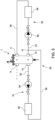
- Figure 5 shows the diagram of a thermal system 50 using the separator 1 according to the invention and comprising a primary circuit 51 and a secondary circuit 52.
- the separator 1 is shown in a schematic fashion and the sole sleeves 9, 10, 11, 12 are indicated, whereas the relative joints, if present, are not indicated.
- the primary circuit 51 comprises an input line 53, a pump 54, a generator 55, for example a boiler, and a return line 56, which is mechanically connected to the sleeve 9, but is hydraulically connected, as discussed above, to the sleeve 12 by means of the tube 49.
- the sleeve 10 defines (or is connected to) a connection for the input line 53.
- the secondary circuit comprises an input line 57 connected to the sleeve 12 of the separator 1, a pump 58, at least one utility 59 and a return line 60 connected to the sleeve 11 of the separator 1.
- the sleeve 11 defines (or is connected to) a connection for the return line 60.
- the separator 1 works as follows.
- the remaining particles are held back by the filter 25: the heavier ones precipitate towards the bottom wall 27 due to gravity, the lighter ones are held back on the inside through direct filtration.
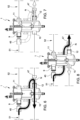
- Figure 8 shows the behaviour in case both the primary circuit and the secondary circuit are active and the flow rate of the primary circuit is the same as the flow rate of the secondary circuit; in this case, the separator 1 fulfils the task of filtration of the return flow and of direct connection between the output of the primary circuit and the input of the secondary circuit. Since there is no intersection between the flows on the inside of the body 2 of the separator, there are no parasite currents supported by the stratifying action of conventional separators. For this reason, the separator according to the invention can be used both for heating and for cooling purposes, with no need to change the connections of the pipes.
- Figure 9 shows the case in which the secondary circuit 52 requires a greater flow rate compared to the one provided by the primary circuit 51.
- the separator fulfils the task of hydraulic separation between the circuits, ensuring the magnetic filtration of the entire flow rate coming from the secondary circuit.
- figure 10 shows the opposite case in which the secondary circuit 52 requires a smaller flow rate compared to the one provided by the primary circuit 51.
- the excess flow rate of the primary circuit is recirculated through the separator 1, which also carries out the magnetic filtration of the entire flow rate coming from the secondary circuit.
- the use of the tube 49 allows the physical connection of the delivery and return lines of the primary circuit to be carried out on the same side of the separator 1, with evident advantages in terms of assembly easiness. Furthermore, the physical connections are identical to those of a conventional separator, which makes it easier for them to be assembled by plumbers who are used to using conventional separators.
Landscapes
- Chemical & Material Sciences (AREA)
- Engineering & Computer Science (AREA)
- Chemical Kinetics & Catalysis (AREA)
- Physics & Mathematics (AREA)
- Thermal Sciences (AREA)
- Combustion & Propulsion (AREA)
- Mechanical Engineering (AREA)
- General Engineering & Computer Science (AREA)
- Water Supply & Treatment (AREA)
- Fluid-Pressure Circuits (AREA)
Claims (15)
- Séparateur hydraulique pour un système thermique (50) prévu avec un circuit principal (51) et un circuit secondaire (52), comprenant un corps (2) avec un axe vertical (A), définissant une chambre interne (5) et équipé avec un premier raccordement (45) pour se raccorder à une conduite de retour (56) du circuit principal (51), un deuxième raccordement pour se raccorder à une conduite d'entrée du circuit principal (51), un troisième raccordement pour se raccorder à une conduite de retour (60) du circuit secondaire (52) et un quatrième raccordement (47) pour se raccorder à une conduite d'entrée (58) du circuit secondaire (52), et un filtre (25) logé dans ladite chambre interne (5) et intercalé entre une première zone (5a) de la chambre interne (5) communiquant avec le troisième raccordement (11) et une deuxième zone (5b) de la chambre interne (5) communiquant avec les deuxième et quatrième raccordements (10, 12),
caractérisé en ce que le premier raccordement (45) et le quatrième raccordement (47) sont raccordés entre eux par le biais d'un noeud (N) à l'extérieur de ladite chambre interne (5). - Séparateur selon la revendication 1, dans lequel le corps (2) comprend un premier manchon (9), un deuxième manchon (10), un troisième manchon (11) et un quatrième manchon (12) agencés deux par deux (9, 11) (10, 12) au niveau des côtés opposés du corps, les premier et troisième manchons (9, 11) communiquant avec la première zone (5a) de la chambre interne (5), les deuxième et quatrième manchons (10, 12) communiquant avec la deuxième zone (5b) de la chambre interne (5).
- Séparateur selon la revendication 2, dans lequel le premier manchon (9) est fermé et le premier raccordement (45) est coaxial et mécaniquement raccordé au premier manchon (9).
- Séparateur selon la revendication 3, dans lequel le premier manchon (9) est fermé par un joint borgne rotatif (46) auquel le premier raccordement (45) est mécaniquement raccordé.
- Séparateur selon l'une quelconque des revendications 2 à 4, dans lequel le quatrième raccordement (47) est coaxial et raccordé, par voie hydraulique, au quatrième manchon (12).
- Séparateur selon la revendication 5, dans lequel le quatrième raccordement (47) est raccordé au quatrième manchon (12) au moyen d'un joint débouchant rotatif (12).
- Séparateur selon l'une quelconque des revendications précédentes, dans lequel le premier raccordement (45) et le quatrième raccordement (47) sont raccordés par un tuyau (49) à l'extérieur de la chambre interne (5) et formant ledit noeud (N) avec le quatrième raccordement (47).
- Séparateur selon la revendication 7, dans lequel le premier raccordement (45), le quatrième raccordement (47) et le tube (49) sont assemblés, de manière solidaire, ensemble.
- Séparateur selon l'une quelconque des revendications 2 à 8, dans lequel les deuxième et troisième manchons (10, 11) définissent ou sont raccordés aux deuxième et troisième raccordements respectivement.
- Séparateur selon l'une quelconque des revendications précédentes, dans lequel le corps (2) est fermé au sommet par un couvercle (6) amovible.
- Séparateur selon l'une quelconque des revendications ci-dessus, dans lequel le filtre (25) est en forme de panier et comprend une paroi latérale (26) réalisée avec un matériau filtrant.
- Séparateur selon la revendication 11, dans lequel le filtre comprend une paroi inférieure (27), dans lequel une valve (35) normalement ouverte communique avec un conduit de purge (37) et est équipée avec un obturateur (40) configuré pour se fermer automatiquement lorsque le filtre (25) est retiré du corps (2).
- Séparateur selon l'une quelconque des revendications précédentes, comprenant au moins un aimant (20) logé dans la première zone (5a) de la chambre interne (5) pour intercepter des particules magnétiques en suspension dans l'écoulement entrant depuis le troisième manchon (11).
- Système thermique (50) équipé d'un circuit principal (51) et d'un circuit secondaire (52) ayant des conduites d'entrée (54, 58) respectives et des conduites de retour (56, 60) respectives et un séparateur hydraulique (1) selon l'une quelconque des revendications ci-dessus et ayant le premier raccordement (45) raccordé à la conduite de retour (56) du circuit principal (51), le deuxième raccordement raccordé à la conduite d'entrée du circuit principal (51), le troisième raccordement raccordé à la conduite de retour (60) du circuit secondaire (52) et le quatrième raccordement (47) raccordé à la conduite d'entrée (58) du circuit secondaire (52).
- Système selon la revendication 14, dans lequel la conduite d'entrée (54) du circuit principal (42) est raccordée à la conduite d'entrée (58) du circuit secondaire (52) dans ledit noeud (N).
Priority Applications (2)
| Application Number | Priority Date | Filing Date | Title |
|---|---|---|---|
| SI202130275T SI4001777T1 (sl) | 2020-11-20 | 2021-11-19 | Hidravlični separator za termični sistem |
| HRP20250201TT HRP20250201T1 (hr) | 2020-11-20 | 2021-11-19 | Hidraulični separator za termički sustav |
Applications Claiming Priority (1)
| Application Number | Priority Date | Filing Date | Title |
|---|---|---|---|
| IT102020000027915A IT202000027915A1 (it) | 2020-11-20 | 2020-11-20 | Separatore idraulico per un impianto termico |
Publications (2)
| Publication Number | Publication Date |
|---|---|
| EP4001777A1 EP4001777A1 (fr) | 2022-05-25 |
| EP4001777B1 true EP4001777B1 (fr) | 2025-01-01 |
Family
ID=74557104
Family Applications (1)
| Application Number | Title | Priority Date | Filing Date |
|---|---|---|---|
| EP21209373.6A Active EP4001777B1 (fr) | 2020-11-20 | 2021-11-19 | Séparateur hydraulique pour un système thermique |
Country Status (7)
| Country | Link |
|---|---|
| EP (1) | EP4001777B1 (fr) |
| ES (1) | ES3012539T3 (fr) |
| HR (1) | HRP20250201T1 (fr) |
| HU (1) | HUE069860T2 (fr) |
| IT (1) | IT202000027915A1 (fr) |
| PT (1) | PT4001777T (fr) |
| SI (1) | SI4001777T1 (fr) |
Family Cites Families (4)
| Publication number | Priority date | Publication date | Assignee | Title |
|---|---|---|---|---|
| DE8806448U1 (de) * | 1988-05-17 | 1989-06-29 | Strawa Wärmetechnische Produkte GmbH & Co KG, 7347 Bad Überkingen | Wärmestromtauscher für Mehrkessel-Heizungsanlagen |
| DE20304324U1 (de) * | 2003-03-17 | 2003-07-10 | Comfort Sinusverteiler GmbH, 48493 Wettringen | Hydraulische Weiche |
| DE202005005008U1 (de) * | 2005-03-24 | 2005-07-28 | Comfort Sinusverteiler Gmbh | Rohrverteiler für eine Heizungs- oder Kühlanlage |
| IT1401380B1 (it) * | 2009-10-09 | 2013-07-18 | Graziotto | Equilibratore idraulico con dispositivi interni di separazione e sfogo aria, filtro in linea defangatore per decantazione ispezionabile, compatto per circuiti idraulici e di scambio termico. |
-
2020
- 2020-11-20 IT IT102020000027915A patent/IT202000027915A1/it unknown
-
2021
- 2021-11-19 SI SI202130275T patent/SI4001777T1/sl unknown
- 2021-11-19 PT PT212093736T patent/PT4001777T/pt unknown
- 2021-11-19 EP EP21209373.6A patent/EP4001777B1/fr active Active
- 2021-11-19 ES ES21209373T patent/ES3012539T3/es active Active
- 2021-11-19 HR HRP20250201TT patent/HRP20250201T1/hr unknown
- 2021-11-19 HU HUE21209373A patent/HUE069860T2/hu unknown
Also Published As
| Publication number | Publication date |
|---|---|
| SI4001777T1 (sl) | 2025-04-30 |
| HUE069860T2 (hu) | 2025-04-28 |
| HRP20250201T1 (hr) | 2025-04-11 |
| ES3012539T3 (en) | 2025-04-09 |
| PT4001777T (pt) | 2025-01-13 |
| IT202000027915A1 (it) | 2022-05-20 |
| EP4001777A1 (fr) | 2022-05-25 |
Similar Documents
| Publication | Publication Date | Title |
|---|---|---|
| KR101690083B1 (ko) | 자기적 여과 장치 | |
| EP3801815B1 (fr) | Dispositif et procédé de filtrage d'un fluide circulant dans un système de plomberie et de chauffage | |
| US4582605A (en) | In-line pipeline strainer | |
| EP3752267B1 (fr) | Dispositif et procédé de filtrage d'un fluide circulant dans un système de plomberie et de chauffage | |
| KR101581249B1 (ko) | 버킷형 스트레이너 | |
| US12214305B2 (en) | Device and method for filtering a fluid circulating in a plumbing and heating system | |
| EP3449995B1 (fr) | Filtre desemboueur | |
| EP4001777B1 (fr) | Séparateur hydraulique pour un système thermique | |
| IT201600119549A1 (it) | Dispositivo filtro defangatore | |
| US12312261B2 (en) | Magnetic water filter assembly | |
| KR100868810B1 (ko) | 인라인형 스트레이너 | |
| EP3640509B1 (fr) | Collecteur de distribution d'un fluide | |
| EP3229933A1 (fr) | Séparateur et procédé | |
| CN217247333U (zh) | 用于集中供暖和/或制冷系统的过滤器 | |
| CN210302656U (zh) | 多联过滤装置 | |
| CN221385381U (zh) | 冷却液过滤装置及储能设备冷却系统 | |
| US4412479A (en) | Gas flow arrangement | |
| US12370476B2 (en) | Device and method for filtering a fluid circulating in a plumbing and heating system | |
| KR20170109853A (ko) | 스트레이너 | |
| BR102024025980A2 (pt) | Elemento de filtro e módulo de filtro | |
| WO2023032069A1 (fr) | Dispositif d'élimination de corps étrangers | |
| EA040052B1 (ru) | Устройство и способ фильтрации текучей среды, циркулирующей в водопроводной и отопительной системе | |
| EA040673B1 (ru) | Устройство и способ фильтрации текучей среды, циркулирующей в сантехнической и отопительной системе | |
| PL170654B1 (pl) | Filtroodmulnik magnetyczny | |
| MXPA01005962A (en) | Coolant filter assembly kit for a vehicle, coolant filter assembly formed therefrom, and method of using same |
Legal Events
| Date | Code | Title | Description |
|---|---|---|---|
| REG | Reference to a national code |
Ref country code: HR Ref legal event code: TUEP Ref document number: P20250201T Country of ref document: HR |
|
| PUAI | Public reference made under article 153(3) epc to a published international application that has entered the european phase |
Free format text: ORIGINAL CODE: 0009012 |
|
| STAA | Information on the status of an ep patent application or granted ep patent |
Free format text: STATUS: THE APPLICATION HAS BEEN PUBLISHED |
|
| AK | Designated contracting states |
Kind code of ref document: A1 Designated state(s): AL AT BE BG CH CY CZ DE DK EE ES FI FR GB GR HR HU IE IS IT LI LT LU LV MC MK MT NL NO PL PT RO RS SE SI SK SM TR |
|
| STAA | Information on the status of an ep patent application or granted ep patent |
Free format text: STATUS: REQUEST FOR EXAMINATION WAS MADE |
|
| 17P | Request for examination filed |
Effective date: 20221125 |
|
| RBV | Designated contracting states (corrected) |
Designated state(s): AL AT BE BG CH CY CZ DE DK EE ES FI FR GB GR HR HU IE IS IT LI LT LU LV MC MK MT NL NO PL PT RO RS SE SI SK SM TR |
|
| RAP1 | Party data changed (applicant data changed or rights of an application transferred) |
Owner name: R.B.M. S.P.A. |
|
| GRAP | Despatch of communication of intention to grant a patent |
Free format text: ORIGINAL CODE: EPIDOSNIGR1 |
|
| STAA | Information on the status of an ep patent application or granted ep patent |
Free format text: STATUS: GRANT OF PATENT IS INTENDED |
|
| RIC1 | Information provided on ipc code assigned before grant |
Ipc: B03C 1/30 20060101ALI20240515BHEP Ipc: B03C 1/28 20060101ALI20240515BHEP Ipc: B03C 1/033 20060101ALI20240515BHEP Ipc: F24D 19/00 20060101ALI20240515BHEP Ipc: B03C 1/00 20060101ALI20240515BHEP Ipc: B01D 29/23 20060101ALI20240515BHEP Ipc: B01D 35/06 20060101ALI20240515BHEP Ipc: B01D 35/153 20060101ALI20240515BHEP Ipc: B01D 36/00 20060101ALI20240515BHEP Ipc: F24D 3/10 20060101AFI20240515BHEP |
|
| INTG | Intention to grant announced |
Effective date: 20240617 |
|
| GRAS | Grant fee paid |
Free format text: ORIGINAL CODE: EPIDOSNIGR3 |
|
| P01 | Opt-out of the competence of the unified patent court (upc) registered |
Free format text: CASE NUMBER: APP_53348/2024 Effective date: 20240925 |
|
| GRAA | (expected) grant |
Free format text: ORIGINAL CODE: 0009210 |
|
| STAA | Information on the status of an ep patent application or granted ep patent |
Free format text: STATUS: THE PATENT HAS BEEN GRANTED |
|
| AK | Designated contracting states |
Kind code of ref document: B1 Designated state(s): AL AT BE BG CH CY CZ DE DK EE ES FI FR GB GR HR HU IE IS IT LI LT LU LV MC MK MT NL NO PL PT RO RS SE SI SK SM TR |
|
| REG | Reference to a national code |
Ref country code: GB Ref legal event code: FG4D |
|
| REG | Reference to a national code |
Ref country code: PT Ref legal event code: SC4A Ref document number: 4001777 Country of ref document: PT Date of ref document: 20250113 Kind code of ref document: T Free format text: AVAILABILITY OF NATIONAL TRANSLATION Effective date: 20250106 |
|
| REG | Reference to a national code |
Ref country code: CH Ref legal event code: EP |
|
| REG | Reference to a national code |
Ref country code: DE Ref legal event code: R096 Ref document number: 602021024192 Country of ref document: DE |
|
| REG | Reference to a national code |
Ref country code: IE Ref legal event code: FG4D |
|
| REG | Reference to a national code |
Ref country code: NL Ref legal event code: FP |
|
| REG | Reference to a national code |
Ref country code: ES Ref legal event code: FG2A Ref document number: 3012539 Country of ref document: ES Kind code of ref document: T3 Effective date: 20250409 |
|
| REG | Reference to a national code |
Ref country code: HR Ref legal event code: T1PR Ref document number: P20250201 Country of ref document: HR |
|
| REG | Reference to a national code |
Ref country code: LT Ref legal event code: MG9D |
|
| REG | Reference to a national code |
Ref country code: HU Ref legal event code: AG4A Ref document number: E069860 Country of ref document: HU |
|
| PG25 | Lapsed in a contracting state [announced via postgrant information from national office to epo] |
Ref country code: FI Free format text: LAPSE BECAUSE OF FAILURE TO SUBMIT A TRANSLATION OF THE DESCRIPTION OR TO PAY THE FEE WITHIN THE PRESCRIBED TIME-LIMIT Effective date: 20250101 |
|
| PG25 | Lapsed in a contracting state [announced via postgrant information from national office to epo] |
Ref country code: PL Free format text: LAPSE BECAUSE OF FAILURE TO SUBMIT A TRANSLATION OF THE DESCRIPTION OR TO PAY THE FEE WITHIN THE PRESCRIBED TIME-LIMIT Effective date: 20250101 |
|
| PG25 | Lapsed in a contracting state [announced via postgrant information from national office to epo] |
Ref country code: IS Free format text: LAPSE BECAUSE OF FAILURE TO SUBMIT A TRANSLATION OF THE DESCRIPTION OR TO PAY THE FEE WITHIN THE PRESCRIBED TIME-LIMIT Effective date: 20250501 Ref country code: NO Free format text: LAPSE BECAUSE OF FAILURE TO SUBMIT A TRANSLATION OF THE DESCRIPTION OR TO PAY THE FEE WITHIN THE PRESCRIBED TIME-LIMIT Effective date: 20250401 |
|
| PG25 | Lapsed in a contracting state [announced via postgrant information from national office to epo] |
Ref country code: LV Free format text: LAPSE BECAUSE OF FAILURE TO SUBMIT A TRANSLATION OF THE DESCRIPTION OR TO PAY THE FEE WITHIN THE PRESCRIBED TIME-LIMIT Effective date: 20250101 |
|
| PG25 | Lapsed in a contracting state [announced via postgrant information from national office to epo] |
Ref country code: GR Free format text: LAPSE BECAUSE OF FAILURE TO SUBMIT A TRANSLATION OF THE DESCRIPTION OR TO PAY THE FEE WITHIN THE PRESCRIBED TIME-LIMIT Effective date: 20250402 Ref country code: BG Free format text: LAPSE BECAUSE OF FAILURE TO SUBMIT A TRANSLATION OF THE DESCRIPTION OR TO PAY THE FEE WITHIN THE PRESCRIBED TIME-LIMIT Effective date: 20250101 |
|
| PG25 | Lapsed in a contracting state [announced via postgrant information from national office to epo] |
Ref country code: SE Free format text: LAPSE BECAUSE OF FAILURE TO SUBMIT A TRANSLATION OF THE DESCRIPTION OR TO PAY THE FEE WITHIN THE PRESCRIBED TIME-LIMIT Effective date: 20250101 |
|
| REG | Reference to a national code |
Ref country code: DE Ref legal event code: R097 Ref document number: 602021024192 Country of ref document: DE |
|
| PG25 | Lapsed in a contracting state [announced via postgrant information from national office to epo] |
Ref country code: SM Free format text: LAPSE BECAUSE OF FAILURE TO SUBMIT A TRANSLATION OF THE DESCRIPTION OR TO PAY THE FEE WITHIN THE PRESCRIBED TIME-LIMIT Effective date: 20250101 |
|
| PG25 | Lapsed in a contracting state [announced via postgrant information from national office to epo] |
Ref country code: DK Free format text: LAPSE BECAUSE OF FAILURE TO SUBMIT A TRANSLATION OF THE DESCRIPTION OR TO PAY THE FEE WITHIN THE PRESCRIBED TIME-LIMIT Effective date: 20250101 |
|
| PG25 | Lapsed in a contracting state [announced via postgrant information from national office to epo] |
Ref country code: EE Free format text: LAPSE BECAUSE OF FAILURE TO SUBMIT A TRANSLATION OF THE DESCRIPTION OR TO PAY THE FEE WITHIN THE PRESCRIBED TIME-LIMIT Effective date: 20250101 |
|
| PG25 | Lapsed in a contracting state [announced via postgrant information from national office to epo] |
Ref country code: RO Free format text: LAPSE BECAUSE OF FAILURE TO SUBMIT A TRANSLATION OF THE DESCRIPTION OR TO PAY THE FEE WITHIN THE PRESCRIBED TIME-LIMIT Effective date: 20250101 |
|
| PG25 | Lapsed in a contracting state [announced via postgrant information from national office to epo] |
Ref country code: SK Free format text: LAPSE BECAUSE OF FAILURE TO SUBMIT A TRANSLATION OF THE DESCRIPTION OR TO PAY THE FEE WITHIN THE PRESCRIBED TIME-LIMIT Effective date: 20250101 |
|
| PLBE | No opposition filed within time limit |
Free format text: ORIGINAL CODE: 0009261 |
|
| STAA | Information on the status of an ep patent application or granted ep patent |
Free format text: STATUS: NO OPPOSITION FILED WITHIN TIME LIMIT |
|
| 26N | No opposition filed |
Effective date: 20251002 |
|
| PGFP | Annual fee paid to national office [announced via postgrant information from national office to epo] |
Ref country code: AT Payment date: 20260113 Year of fee payment: 5 |
|
| REG | Reference to a national code |
Ref country code: AT Ref legal event code: UEP Ref document number: 1756590 Country of ref document: AT Kind code of ref document: T Effective date: 20250101 |