EP4001780B1 - Klimaanlage - Google Patents
Klimaanlage Download PDFInfo
- Publication number
- EP4001780B1 EP4001780B1 EP21208001.4A EP21208001A EP4001780B1 EP 4001780 B1 EP4001780 B1 EP 4001780B1 EP 21208001 A EP21208001 A EP 21208001A EP 4001780 B1 EP4001780 B1 EP 4001780B1
- Authority
- EP
- European Patent Office
- Prior art keywords
- vane
- link
- stopper
- disposed
- air conditioner
- Prior art date
- Legal status (The legal status is an assumption and is not a legal conclusion. Google has not performed a legal analysis and makes no representation as to the accuracy of the status listed.)
- Active
Links
Images


Classifications
-
- F—MECHANICAL ENGINEERING; LIGHTING; HEATING; WEAPONS; BLASTING
- F24—HEATING; RANGES; VENTILATING
- F24F—AIR-CONDITIONING; AIR-HUMIDIFICATION; VENTILATION; USE OF AIR CURRENTS FOR SCREENING
- F24F1/00—Room units for air-conditioning, e.g. separate or self-contained units or units receiving primary air from a central station
- F24F1/0007—Indoor units, e.g. fan coil units
- F24F1/0011—Indoor units, e.g. fan coil units characterised by air outlets
-
- F—MECHANICAL ENGINEERING; LIGHTING; HEATING; WEAPONS; BLASTING
- F24—HEATING; RANGES; VENTILATING
- F24F—AIR-CONDITIONING; AIR-HUMIDIFICATION; VENTILATION; USE OF AIR CURRENTS FOR SCREENING
- F24F13/00—Details common to, or for air-conditioning, air-humidification, ventilation or use of air currents for screening
- F24F13/20—Casings or covers
-
- F—MECHANICAL ENGINEERING; LIGHTING; HEATING; WEAPONS; BLASTING
- F24—HEATING; RANGES; VENTILATING
- F24F—AIR-CONDITIONING; AIR-HUMIDIFICATION; VENTILATION; USE OF AIR CURRENTS FOR SCREENING
- F24F1/00—Room units for air-conditioning, e.g. separate or self-contained units or units receiving primary air from a central station
- F24F1/0007—Indoor units, e.g. fan coil units
- F24F1/0043—Indoor units, e.g. fan coil units characterised by mounting arrangements
- F24F1/0057—Indoor units, e.g. fan coil units characterised by mounting arrangements mounted in or on a wall
-
- F—MECHANICAL ENGINEERING; LIGHTING; HEATING; WEAPONS; BLASTING
- F24—HEATING; RANGES; VENTILATING
- F24F—AIR-CONDITIONING; AIR-HUMIDIFICATION; VENTILATION; USE OF AIR CURRENTS FOR SCREENING
- F24F13/00—Details common to, or for air-conditioning, air-humidification, ventilation or use of air currents for screening
- F24F13/08—Air-flow control members, e.g. louvres, grilles, flaps or guide plates
- F24F13/10—Air-flow control members, e.g. louvres, grilles, flaps or guide plates movable, e.g. dampers
- F24F13/14—Air-flow control members, e.g. louvres, grilles, flaps or guide plates movable, e.g. dampers built up of tilting members, e.g. louvre
- F24F13/1413—Air-flow control members, e.g. louvres, grilles, flaps or guide plates movable, e.g. dampers built up of tilting members, e.g. louvre using more than one tilting member, e.g. with several pivoting blades
-
- F—MECHANICAL ENGINEERING; LIGHTING; HEATING; WEAPONS; BLASTING
- F24—HEATING; RANGES; VENTILATING
- F24F—AIR-CONDITIONING; AIR-HUMIDIFICATION; VENTILATION; USE OF AIR CURRENTS FOR SCREENING
- F24F13/00—Details common to, or for air-conditioning, air-humidification, ventilation or use of air currents for screening
- F24F13/08—Air-flow control members, e.g. louvres, grilles, flaps or guide plates
- F24F13/10—Air-flow control members, e.g. louvres, grilles, flaps or guide plates movable, e.g. dampers
- F24F13/14—Air-flow control members, e.g. louvres, grilles, flaps or guide plates movable, e.g. dampers built up of tilting members, e.g. louvre
- F24F13/1426—Air-flow control members, e.g. louvres, grilles, flaps or guide plates movable, e.g. dampers built up of tilting members, e.g. louvre characterised by actuating means
-
- F—MECHANICAL ENGINEERING; LIGHTING; HEATING; WEAPONS; BLASTING
- F24—HEATING; RANGES; VENTILATING
- F24F—AIR-CONDITIONING; AIR-HUMIDIFICATION; VENTILATION; USE OF AIR CURRENTS FOR SCREENING
- F24F13/00—Details common to, or for air-conditioning, air-humidification, ventilation or use of air currents for screening
- F24F13/08—Air-flow control members, e.g. louvres, grilles, flaps or guide plates
- F24F13/10—Air-flow control members, e.g. louvres, grilles, flaps or guide plates movable, e.g. dampers
- F24F13/14—Air-flow control members, e.g. louvres, grilles, flaps or guide plates movable, e.g. dampers built up of tilting members, e.g. louvre
- F24F13/1486—Air-flow control members, e.g. louvres, grilles, flaps or guide plates movable, e.g. dampers built up of tilting members, e.g. louvre characterised by bearings, pivots or hinges
-
- F—MECHANICAL ENGINEERING; LIGHTING; HEATING; WEAPONS; BLASTING
- F24—HEATING; RANGES; VENTILATING
- F24F—AIR-CONDITIONING; AIR-HUMIDIFICATION; VENTILATION; USE OF AIR CURRENTS FOR SCREENING
- F24F13/00—Details common to, or for air-conditioning, air-humidification, ventilation or use of air currents for screening
- F24F13/08—Air-flow control members, e.g. louvres, grilles, flaps or guide plates
- F24F13/10—Air-flow control members, e.g. louvres, grilles, flaps or guide plates movable, e.g. dampers
- F24F13/14—Air-flow control members, e.g. louvres, grilles, flaps or guide plates movable, e.g. dampers built up of tilting members, e.g. louvre
- F24F13/1426—Air-flow control members, e.g. louvres, grilles, flaps or guide plates movable, e.g. dampers built up of tilting members, e.g. louvre characterised by actuating means
- F24F2013/1433—Air-flow control members, e.g. louvres, grilles, flaps or guide plates movable, e.g. dampers built up of tilting members, e.g. louvre characterised by actuating means with electric motors
-
- F—MECHANICAL ENGINEERING; LIGHTING; HEATING; WEAPONS; BLASTING
- F24—HEATING; RANGES; VENTILATING
- F24F—AIR-CONDITIONING; AIR-HUMIDIFICATION; VENTILATION; USE OF AIR CURRENTS FOR SCREENING
- F24F13/00—Details common to, or for air-conditioning, air-humidification, ventilation or use of air currents for screening
- F24F13/08—Air-flow control members, e.g. louvres, grilles, flaps or guide plates
- F24F13/10—Air-flow control members, e.g. louvres, grilles, flaps or guide plates movable, e.g. dampers
- F24F13/14—Air-flow control members, e.g. louvres, grilles, flaps or guide plates movable, e.g. dampers built up of tilting members, e.g. louvre
- F24F13/1426—Air-flow control members, e.g. louvres, grilles, flaps or guide plates movable, e.g. dampers built up of tilting members, e.g. louvre characterised by actuating means
- F24F2013/1473—Air-flow control members, e.g. louvres, grilles, flaps or guide plates movable, e.g. dampers built up of tilting members, e.g. louvre characterised by actuating means with cams or levers
-
- F—MECHANICAL ENGINEERING; LIGHTING; HEATING; WEAPONS; BLASTING
- F24—HEATING; RANGES; VENTILATING
- F24F—AIR-CONDITIONING; AIR-HUMIDIFICATION; VENTILATION; USE OF AIR CURRENTS FOR SCREENING
- F24F13/00—Details common to, or for air-conditioning, air-humidification, ventilation or use of air currents for screening
- F24F13/20—Casings or covers
- F24F2013/205—Mounting a ventilator fan therein
-
- F—MECHANICAL ENGINEERING; LIGHTING; HEATING; WEAPONS; BLASTING
- F24—HEATING; RANGES; VENTILATING
- F24F—AIR-CONDITIONING; AIR-HUMIDIFICATION; VENTILATION; USE OF AIR CURRENTS FOR SCREENING
- F24F2221/00—Details or features not otherwise provided for
- F24F2221/17—Details or features not otherwise provided for mounted in a wall
Definitions
- the present invention relates to an air conditioner, and more particularly to an air conditioner having two vanes disposed at a discharge port.
- An air conditioner includes a compressor for compressing a refrigerant, a condenser for condensing the compressed refrigerant, an expander for expanding the condensed refrigerant, and an evaporator for evaporating the expanded refrigerant, and by flowing the refrigerant through this structure, the air conditioner may heat or cool indoor air to maintain the air at a proper temperature.
- the air conditioner may include an indoor unit having a heat exchanger for heat exchanging indoor air, and an outdoor unit for heat exchanging outdoor air.
- the heat exchanger mounted in each of the indoor and outdoor units, may function as an evaporator or a condenser depending on the flow of the refrigerant.
- the air conditioner may be divided into a ceiling-mounted air conditioner, a floor standing type air conditioner, and a wall-mounted air conditioner, depending on an arrangement and a structure of the air conditioner.
- the air conditioner is installed on an upper wall surface of a room, and has a discharge port for discharging heat-exchanged air in a downward and forward direction.
- one or two vanes may be disposed at the discharge port so as to expand a wind direction range of the air discharged through the discharge port.
- KR10-2005-0066463 discloses an air conditioner having two vanes. However, the respective vanes are rotatably fixed to a case, such that a wind direction range of the air discharged through the discharge port may be limited.
- KR 10-2020-0075559 discloses a ceiling-mounted air conditioner having a structure in which an arrangement of two vanes is changed by two or more links.
- the ceiling-mounted air conditioner has a structure in which a discharge passage is formed at a lower side, such that if the same structure is to be applied to the wall-mounted air conditioner, there is a limitation in changing an arrangement for covering a discharge port of the wall-mounted air conditioner or for guiding the discharged air.
- JP 2008 122003 A shows an air conditioner with a variable arm part; a wind direction changing blade controlling the vertical direction of air blown off from a blowout port; a first driving means for driving the arm part; a second driving means for driving the wind direction changing blade; and a driving means control part for controlling driving of at least the first and second driving means.
- the wall-mounted air conditioner having a discharge passage which is inclined forwardly and downwardly, it is required to increase a rotation range of vanes in order to cover a discharge port or to increase a wind direction range of the air discharged through the discharge port.
- the wall-mounted air conditioner has a structure in which a discharge port is vertically elongated and vanes for covering the discharge port are moved by a plurality of links, such that even when the vanes are disposed at the discharge port, a gap between the discharge port and the vanes may easily occur.
- an air conditioner comprising case having a suction port, a discharge port formed below the suction port, and a discharge passage for guiding air to the discharge port; a blower fan disposed inside the case, the blower fan is configured to generate an air flow from the suction port to the discharge port; a first vane for closing the discharge port or for guiding the air discharged through the discharge port; a first link connected to one side of the first vane; a second link connected to the other side of the first vane; a motor configured to rotate the first link; and a first stopper disposed at the discharge port to come into contact with an upper end of the first vane; characterized by a second stopper disposed at the discharge port to come into contact with a lower end of the first vane, wherein when the first link rotates so that the first vane closes the discharge port, the first stopper comes into contact with the first vane earlier than the second stopper.
- the air conditioner according to an embodiment of the present invention may include one or more of the optional features.
- the air conditioner includes a first vane closing the discharge port or guiding the air discharged through the discharge port.
- the air conditioner includes a first link connected to one side of the first vane.
- the air conditioner includes a second link connected to the other side of the first vane.
- the air conditioner may include a motor fixed to the case and rotating the first link.
- the air conditioner includes a first stopper disposed at the discharge port to come into contact with an upper end of the first vane.
- the air conditioner includes a second stopper disposed at the discharge port to come into contact with a lower end of the first vane.
- the first stopper comes into contact with the first vane earlier than the second stopper, thereby allowing a lower portion of the first vane to move toward the second stopper. That is, after coming into contact with the first stopper, the first vane comes into contact with the second stopper, such that each of an upper end and a lower end of the first vane may come into contact with the first stopper and the second stopper.
- a rotation center of the first link may be disposed between the first stopper and the second stopper in an up-down direction.
- connection centers of the first link and the first vane when the first vane comes into contact with the first stopper, connection centers of the first link and the first vane may be disposed below the rotation center of the first link, such that an arrangement of a lower part of the first vane may be changed.
- the first link When the first link rotates so that the first vane closes the discharge port, the first link may move the first vane rearwardly, thereby allowing the lower part of the first vane to come into contact with the second stopper.
- the rotation center of the first link may be disposed closer to the second stopper than the first stopper, such that when the first vane is in contact with the first stopper, the arrangement of the first vane disposed closer to the second stopper may be changed.
- connection centers of the first link and the first vane may be disposed behind a virtual line connecting the rotation center of the first link and the second stopper, such that the lower part of the first vane may be easily moved toward the second stopper.
- connection centers of the first link and the first vane may be disposed closer to the second stopper than the first stopper, such that the lower part of the first vane may be moved.
- the first vane may include a first vane plate disposed to partially cover the discharge port or to guide air discharged through the discharge port.
- the first vane may include a first connection plate protruding rearwardly of the first vane plate in a width direction and upwardly from both ends of the first vane plate in a length direction, and rotatably connected to the first link and the second link.
- a width length of the first vane plate may be two to three times a width length of the first connection plate.
- a force exerted by rotation of the first link and the second link may be applied rearwardly of the first vane plate in the width direction.
- the first link may include a rotary plate rotatably disposed in the case.
- the first link may include a fixing link spaced apart from a center of the rotary plate, and extending radially outwardly from the rotary plate.
- the fixing link may be convexly bent, thereby increasing a rotation range of the first vane.
- the first link may include a rotating shaft portion protruding from the center of the rotary plate toward one side, and forming a rotating shaft of the rotary plate.
- the first link may include inner stoppers protruding from the rotary plate in a direction in which the rotating shaft portion is formed, and restricting rotation of the rotary plate, such that the rotation range of the first vane may be double-restricted.
- the case may include a rotation guide having a insertion groove, into which the rotary plate of the first link is rotatably inserted.
- the rotation guide may include an inner protrusion protruding in the insertion groove to restrict rotation of the rotary plate, such that the rotation range of the first vane may be double-restricted.
- the inner stopper When the first vane comes into contact with the first stopper, the inner stopper may be disposed so as not to come into contact with the inner protrusion, thereby allowing the first vane to move until the first vane comes into contact with the second stopper.
- the inner stopper may include a first inner stopper protruding radially outwardly from the rotating shaft portion.
- the inner stopper may include a second inner stopper spaced apart from the first inner stopper in a circumferential direction, and protruding radially outwardly from the rotating shaft portion.
- the first vane When the first inner stopper comes into contact with the inner protrusion, the first vane may come into contact with the second stopper, thereby restricting rotation of the first vane.
- a rear end of the first vane may be disposed in between a bent curved surface of the fixing link, thereby preventing contact between the first vane and the first link.
- the second link may be rotatably connected to the first vane at a rear side of the first vane in the width direction, such that when the first vane comes into contact with the first stopper, the rear side of the first vane may be easily moved.
- the air conditioner may further include a second vane rotatably disposed on one side of the case, and guiding air flowing through the discharge passage.
- the air conditioner may further include a third link rotatably connected to the first link, and changing an arrangement of the second vane.
- the second vane When the first vane comes into contact with the first stopper, the second vane may be disposed on the discharge port, such that when the first vane closes the discharge port, the second vane may be disposed inside the discharge port.
- the air conditioner of to the present invention has one or more of the following effects.
- a movement range of the first vane may be expanded such that in a structure where the discharge passage is formed at a lower front side, the first vane may cover the discharge port or may allow air, discharged through the discharge port, to flow forwardly or downwardly. That is, in consideration of temperature of the discharged air, temperature of a room may rapidly reach a target temperature.
- the present invention provides a structure in which movement of the first vane is restricted by the first stopper and the second stopper, and rotation of the first link is further restricted by the inner stopper, such that rotation of the first vane to a region outside of a moving range may be double-restricted.
- FIGS. 1 to 6 the overall configuration of an air conditioner according to an embodiment of the present invention will be described with reference to FIGS. 1 to 6 .
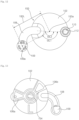
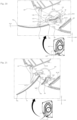
- the air conditioner includes: a case 10 forming the exterior of the air conditioner and having a suction port 22 and a discharge port 24; a heat exchanger 28 heating or cooling air flowing in the case 10; a blower fan 26 causing the air in the case 10 to flow to the discharge port 24; and a discharge guider 30 guiding the air blown by the blower fan 26 to the discharge port 24.
- the case 10 has the suction port 22 which is formed on an upper wall 12 or an upper portion of a front wall 14, and through which air is suctioned, and the discharge port 24 which is formed on a lower portion of the front wall 14, and through which air is discharged.
- the case 10 may have a cuboid shape which is horizontally elongated.
- the air conditioner relates to a wall-mounted air conditioner, in which the discharge port 24 is formed below the suction port 22 so that the air in the case 10 may flow from top to bottom.
- the suction port 22 may be disposed above a center 26a of the blower fan 26, and the discharge port 24 may be disposed below the center 26a of the blower fan 26.
- an outer circumferential surface of the case 10 may include: an upper wall 12 having the suction port 22 formed therein; a front wall 14 extending downwardly from a front end of the upper wall 12 and disposed to cover a front side; a lower wall 16 disposed in an opposite direction to the upper wall 12; and both side walls 18 ( Fig. 1 ) forming a surface perpendicular to the front wall 14, the upper wall 12, and the lower wall 16.
- the front wall 14 and the lower wall 16 are connected in a curved surface shape, and the discharge port 24 may be formed at a portion where the front wall 14 and the lower wall 16 are connected in the curved surface shape.
- the discharge port 24 may be formed at a lower front side of the case 10
- the case 10 has an inner space in which the heat exchanger 28 and the blower fan 26 are disposed. Inside the case 10, one or more guides may be formed for guiding the air suctioned through the suction port 22 to the blower fan 26, or guiding the air blown by the blower fan 26 to the discharge port 24.
- a discharge guider 30 for guiding the air, blown by the blower fan 26, to the discharge port 24 may be formed in the case 10.
- the discharge guider 30 has a discharge passage 30a, through which the air blown by the blower fan 26 flows.
- the discharge guider 30 guides the air blown by the blower fan 26 to the discharge port 24. Referring to FIG. 2 , the discharge passage 30a extends forwardly and downwardly from the blower fan 26.
- the discharge guider 30 may include an upper guider 36 disposed above the discharge passage 30a and a lower guider 32 disposed below the discharge passage 30a.
- the upper guider 36 is connected to an upper end of the discharge port 24, preferably at a position forward of the center 26a of the blower fan 26.
- the lower guider 32 is connected to a lower end of the discharge port 24, preferably at a position downwardly from the blower fan 26 and/or rearward from the position of the upper guider 36 being connected to the upper end of the discharge port 24..
- the lower guider 32 extends from a rear side of the blower fan 26 to the discharge port 24. So, the lower guider 32 extends higher at the rear side of the blower fan than the center of the blower fan 26a, so as to also guide the air blown to the back side of the air conditioner.
- the lower guider 32 may include a curved surface 32b which is curved so as to guide the air, discharged by the blower fan 26 in a rearward or downward direction from the blower fan 26, toward the discharge port 24; and a straight line surface 32a formed by extending from the curved surface 32b to the discharge port 24.
- a radius of curvature of the curved surface 32b behind the blower 26 is greater than a radius of curvature of the blower fan 26.
- the curved surface 32b may extend up to the rear side of the blower fan 26. The air, blown by the blower fan 26, may be reflected from the curved surface 32b to flow toward the upper guider 26.
- the straight line surface 32a may extend smoothly from the curved surface 32b. Accordingly, the straight line surface 32a may extend at an inclination angle formed by an end portion of the curved surface 32b. The straight line surface 32a may be formed at an inclination angle so that an end portion thereof may be directed forwardly and downwardly.
- the upper guider 36 and the lower guider 32 may form the discharge passage 30a, and the upper guider 36 may be disposed to face the lower guider 32.
- the upper guider 36 may form a straight line surface at a position upstream of the discharge passage 30a.
- the upper guider 36 may form the discharge passage 30a along with the straight line surface 32a.
- the upper guider 36 and the straight line surface 32a are not in parallel to each other. They are running to a widening of the discharge port 24 from inside to the outside.
- the air conditioner 1 includes an inner frame 34 disposed under the heat exchanger 28 to drain condensate falling from the heat exchanger 28.
- the inner frame 34 extend upwardly from the upper guider 36 in an inclined manner.
- the inner frame 34 includes an inner side wall 38, which extends downwardly from both ends of the upper guider 36, in which a plurality of links to be described later are disposed, and which forms both side walls of the discharge passage 30a.
- a pair of inner side walls 38 may be provided, which extend downwardly from each of both ends of the upper guider 36, and each of the pair of inner side walls 38 may be connected to a plurality of links 100, 120, and 130 connected to both ends of a first vane 70 and a second vane 80.
- the inner side wall 38 has a rotation guide 40, in which a rotary plate 102 of a first link 100 which will be described below is rotatably disposed.
- the rotation guide 40 has an insertion groove 41, in which the rotary plate 102 is inserted.
- a center hole 42 in which a rotating shaft portion 104 of the rotary plate 102 is inserted, and which communicates therewith to allow the rotating shaft portion 104 to be coupled to the motor 60, is formed at the center of the rotation guide 40.
- the rotary plate 102 which is inserted into the insertion groove 41, may form a passage, formed by the inner side wall 38, together with the inner side wall 38.
- the rotary plate 102 may form a smooth wall surface together with the inner side wall 38, thereby not interrupting a flow of air flowing through the discharge passage, even when the first link 100 is rotatably mounted to the inner side wall 38.
- the inner side wall 38 may include: a second link connector 46, to which a second link 120 is rotatably fixed; and a second vane connector 48, to which a first protrusion 86 of the second vane 80 is rotatably fixed.
- the second link connector 46 has a first groove 46a in which a first link protrusion 124 of the second link 120 is inserted and fixed.
- the second vane connector 48 has a second groove 48a in which the first protrusion 86 of the second vane 80 is inserted.
- a motor 60 coupled to the rotary plate 102, may be fixedly disposed on the other side of the inner side wall 38 in which the rotary plate 102 is mounted. So, the motor 60 is outside the discharge passage 30a.
- the inner frame 34 includes a supporter 50 including: a first connector 52, to which an auxiliary link 140 which will be described later is rotatably connected; and a second connector 54, to which a third protrusion 92 of the second vane 80 which will be described later is rotatably connected.
- the supporter 50 may be disposed between the pair of inner side walls 38 disposed on both ends of the upper guider 36. At least one supporter 50 may be disposed between the pair of inner side walls 38 disposed on both ends of the upper guider 36. Referring to FIG. 5 , two supporters 50 which are spaced apart from each other in a left-right direction may be disposed at the inner frame 34.
- a first connector 52 may have a first connector hole 52a to which a first auxiliary protrusion 144 of the auxiliary link 140 is coupled.
- the first connector hole 52a may be disposed on the same line as the first groove 46a of the second link connector 46 formed on the inner side wall 38.
- the second connector 54 may have a second connector hole 54a to which the third protrusion 92 of the second vane 80 is coupled.
- the second connector hole 54a may be disposed on the same line as the second groove 48a of the second vane connector 48 which is formed on the inner side wall 38.
- the supporter 50 may rotatably fix each of the auxiliary link 140 and the third protrusion 92 (see FIG. 10 ) of the second vane 80 (see FIG. 10 ).
- the supporter 50 may include a first support bar 56 extending forwardly from the upper guider 36 so as to connect the inner frame 34 and the first connector 52, and a second support bar 58 extending downwardly from the upper guider 36 so as to connect the inner frame 34 and the second connector 54.
- the first connector 52 may be disposed on the same line as the second link connector 46. When viewed from the side, the first connector 52 may be disposed at a position overlapping the second link connector 46.
- the second connector 54 may be disposed on the same line as the second vane connector 48. When viewed from the side, the second connector 54 may be disposed at a position overlapping the second vane connector 48.
- the blower fan 26 causes the air, introduced into the case 10 through the suction port 22, to flow to the discharge port 24.
- a cross flow fan may be used, which draws in and discharges air in a direction perpendicular to a rotation axis direction in which the blower fan 26 rotates.
- the center 26a of the blower fan 26 is disposed below the suction port 22.
- the center 26a of the blower fan 26 is disposed above the discharge port 24.
- the blower fan 26 is disposed under the heat exchanger 28 to allow the air, introduced into the case 10 through the suction port 22 and heat-exchanged with the heat exchanger 28, to flow to the discharge port 24.
- the air conditioner 1 may further include a blower fan motor (not shown) disposed on one side of the blower fan 26 and rotating the blower fan 26.
- a blower fan motor (not shown) disposed on one side of the blower fan 26 and rotating the blower fan 26.
- the heat exchanger 28 may heat exchange with the air, flowing in the case 10, to cool or heat the flowing air.
- the heat exchanger 28 may heat exchange the air flowing in the case 10 by condensing or evaporating a refrigerant flowing therein.
- the heat exchanger 28 is disposed between the blower fan 26 and the suction port 22, to heat exchange outdoor air introduced through the suction port 22.
- the heat exchanger 28 may be disposed in a direction in which the outdoor air is introduced from above the blower fan 26 and flows toward the blower fan 26.
- the air conditioner 1 may further include the first vane 70 and the second vane 80 disposed on the discharge port 24 or the discharge passage 30a to guide a wind direction of the discharged air.
- a configuration of the first vane 70 and the second vane 80, and the plurality of links to change the arrangement thereof will be described in detail below.
- the air conditioner 1 includes: the first vane 70 controlling the air discharged through the discharge port 24; the second vane 80 controlling a direction of the air discharged through the discharge port 24 and having one side rotatably fixed to the case 10; the first link 100 rotatably connected to the case 10 and having one end rotatably connected to the first vane 70; the motor 60 rotating the first link 100; the second link 120 having one end rotatably connected to the case 10 and the other end rotatably connected to the first vane 70; and a third link 130 having one end rotatably connected to the one side of the first link 100 and the other end rotatably connected to the second vane 80.
- the first link 100 and the second link 120 are connected to each of both ends of the first vane 70.
- the third link 130 is connected to each of both ends of the second vane 80.
- the air conditioner 1 includes the auxiliary link 140 supporting the first vane 70 which is moved by the first link 100 and the second link 120.
- the auxiliary link 140 is connected to the first vane 70 at a position between both ends of the first vane 70.
- the first vane 70 is connected to the case 10 by two links 100 and 120 at each of both ends thereof.
- the second vane 80 has one side rotatably connected to the case 10, and the other side connected to the case 10 by the third link 130.
- the links 130 and 140, connected to the first vane 70, are connected to the inner side wall 38 formed on both sides of the discharge port 24 of the case 10.
- One side of the second vane 80 is connected to the inner side wall 38 formed on both sides of the discharge port 24 of the case 10.
- the motor 60 is disposed in an opposite direction to a direction, in which the plurality of links 130 and 140 are disposed, with respect to the inner side wall 38.
- the motor 60 may be fixed to the inner side wall 38 on one side surface of the inner side wall 38.
- the rotation guide 40 in which the rotary plate 102 of the first link 100 which will be described below is disposed, is formed on the inner side wall 38.
- the rotation guide 40 forms a space in which the rotary plate 102 is rotatably mounted.
- the rotation guide 40 has the insertion groove 41 in which the rotary plate 120 is rotatably disposed.
- the rotation guide 40 includes an inner protrusion 44 protruding in the insertion groove 41 to restrict rotation of the rotary plate 102.
- the rotation guide 40 may have the center hole 42, into which the rotating shaft portion 104 of the rotary plate 102 is inserted.
- the first vane 70 and the second vane 80 open and close the discharge port 24 which is open forwardly and downwardly of the case 10.
- the first vane 70 and the second vane 80 control a wind direction of the air discharged through the discharge passage 30a.
- the first vane 70 is connected to the case 10 by the first link 100 and the second link 120. Referring to FIG. 2 , the first vane 70 is not directly connected to the case 10, but is connected to the case 10 by the two links 130 and 140. As an arrangement of the first vane 70 is changed by the first link 100 and the second link 120, the first vane 70 may be disposed perpendicular or parallel to a ground surface. Such connection structure of the first vane 70 may expand a wind direction range of the air discharged from the air conditioner.
- the first vane 70 includes a first vane plate 72 opening and closing the discharge port 24, and a first connection plate 74 protruding from both ends of the first vane plate 72 and connected to the first link 100 and the second link 120.
- the first vane 70 may further include a first support plate 76 protruding upwardly in a height direction (h+, h-) from the first vane plate 72, and connected to the auxiliary link 140.
- a third connection hole 76a connected to one end of the auxiliary link 140 is formed on the first support plate 76.
- the third connection hole 76a may be formed on the same line as a second connection hole 74b formed so that the second link 120 may be connected to the first connection plate 74.
- the third connection hole 76a is disposed at a position overlapping the second connection hole 74b.
- the first vane plate 72 opens and closes the discharge port 24 and controls a discharge direction of the air discharged through the discharge port 24.
- the first vane plate 72 is formed in a size sufficient to cover the discharge port 24 formed in the case 10.
- the first vane plate 72 may form a curved surface which is convex downwardly.
- a plurality of protrusions 72a, extending in the left-right direction, and spaced apart from each other in the front-rear direction, may be formed on an upper surface of the first vane plate 72.
- the first vane 70 is connected to the first link 100 and the second link 120 on a pair of first connection plates 74 disposed on both ends of the first vane plate 72 in the length direction (1+, 1-).
- the pair of first connection plates 74 are disposed on both ends of the first vane plate 72 in the length direction (1+, 1-).
- the first connection plates 74 protrude upwardly in the height direction (h+, h-) from both ends of the first vane plate 72 in the length direction (1+, 1-).
- the first connection plate 74 is formed opposite to the inner side wall 38 of the case 10, to which the first link 100 and the second link 120 are connected.
- the first connection plate 74 protrudes upwardly in the height direction (h+, h-) from the rear side of the first vane plate 72 in the width direction (w+, w-).
- the first connection plate 74 has a first connection hole 74a, rotatably connected to the first link 100, and the second connection hole 74b rotatably connected to the second link 120.
- the first connection hole 74a is disposed above the second connection hole 74b in the height direction (h+, h-).
- the first connection hole 74a is disposed behind the second connection hole 74b in the width direction (w+, w-).
- the first connection plate 74 may include an outer plate 75a having the first connection hole 74a and the second connection hole 74b formed thereon; an inner plate 75b spaced apart from the outer plate 75a; and a circumferential plate 75c connecting the circumference of the outer plate 75a and the inner plate 75b.
- the first connection hole 74a and the second connection hole 74b are formed on the outer plate 75a of the first connection plate 74.
- the outer plate 75a may refer to a direction toward the inner side wall 38.
- the first support plate 76 is disposed between the pair of first connection plates 74.
- the first support plate 76 protrudes upwardly in the height direction (h+, h-) form the upper surface of the first vane plate 72.
- the first support plate 76 is rotatably connected to the auxiliary link 140 which is rotatably connected to the supporter 50. When viewed from the side, the auxiliary link 140 may move together with the second link 120.
- a pair of first support plates 76 may be provided which are spaced apart by a predetermined distance from each other with respect to the first vane plate 72 in the left-right direction.
- a spaced-apart distance 76L between the pair of first support plates 76 may be one-fourth or a half of a length 70L of the first vane 70 formed in the length direction (1+, 1-).
- the spaced-part distance 76L between the pair of first support plates 76 may be one-third of the length 70L of the first vane 70 formed in the length direction (1+, 1-).
- the third connection hole 76 rotatably connected to the auxiliary link 140, is formed on the first support plate 76.
- the third connection hole 76a may be disposed in the same manner as the second connection hole 74b, when viewed from the side.
- a length 70w (“width length of the first vane”) formed along the width direction (w+, w-) of the first vane 70 may be two to three times a length 74w (“width length of the first connection plate") formed along the width direction (w+, w-) of the first connection plate 74.
- the second vane 80 has one side connected to the inner side wall 38 of the case 10, and the other side connected to the inner side wall 38 of the case 10 by the third link 130.
- the second vane 80 rotates as the third link 130 moves with respect to one side of the second vane 80 which is rotatably connected to the case 10.
- the second vane 80 includes: a second vane plate 82 for controlling a direction of the air discharged through the discharge port 24; a second connection plate 84 extending in a direction parallel to the inner side wall 38 from both ends of the second vane plate 82 in the length direction (1+, 1-); the first protrusion 86 protruding in a direction toward the inner side wall 38 from the second connection plate 84, so as to rotatably connect the second vane plate 82 to the case 10; and a second protrusion 88 spaced apart from the first protrusion 86, protruding in a direction toward the inner side wall from the second connection plate 84, and rotatably connected to the third link 130.
- the second vane plate 82 is disposed closer to the blower fan 26 than the first vane plate 72.
- a width length 82w of the second vane plate 82 formed in the front-rear direction is shorter than a width length 72w of the first vane plate 72 formed in the front-rear direction.
- the second vane plate 82 has a bent portion 83 which is convex downwardly.
- the second vane plate 82 includes the bent portion 83 at a portion where the upper plate 82a and the lower plate 82b are connected to each other.
- the upper plate 82a and the lower plate 82b may have a plate shape which is an approximately straight-line shape.
- An included angle between the upper plate 82a and the lower plate 82b may be an obtuse angle which does not significantly change a flow direction of air.
- the second vane plate 82 may form a curved surface which is convex downwardly.
- a radius of curvature formed by the second vane plate 82 may be smaller than a radius of curvature formed by the first vane plate 72.
- a pair of second connection plates 84 are provided which protrude downwardly in the height direction (h+, h-) from both ends of the second vane plate 82.
- the second connection plate 84 is disposed to face the inner side wall 38 of the case 10.
- the second connection plate 84 extends rearwardly of the second vane plate 82 in the width direction (w+, w-) and downwardly of the second vane plate 82 in the height direction (h+, h-).
- the first protrusion 86 and the second protrusion 88 are disposed on the second connection plate 84.
- the second vane 80 rotates as the second protrusion 88 is moved with respect to the first protrusion 86, thereby allowing the air discharged through the discharge port 24 to flow toward an upper surface or a lower surface of the first vane 70.
- a spacer plate 87 for maintaining a space between the inner side wall 38 and the second vane 80 may be disposed on the first protrusion 86.
- the second protrusion 88 is disposed closer to the second vane plate 82 than the first protrusion 86.
- the first protrusion 86 is disposed behind the second protrusion 88 in the width direction (w+, w-).
- a distance 86ah between a center 86a of the first protrusion 86 and the second vane plate 82 may be greater than a distance 88ah between a center 88a of the second protrusion 88 and the second vane plate 82.
- a position of the second protrusion 88 disposed on the inner side wall 38 is below a position of a center 100a of the rotary plate 102 of the first link 100 which is disposed on the inner side wall 38, and which will be described below.
- a position of the second protrusion 88 disposed on the inner side wall 38 is disposed below a position of the first link protrusion 124 of the second link 120 which is disposed on the inner side wall 38, and which will be described below.
- the position of the second protrusion 88 disposed on the inner side wall 38 is disposed behind the position of the center 100a of the rotary plate 102 which is disposed on the inner side wall 38, or a position of one end of the second link 120 which is disposed on the inner side wall 38.
- the second vane plate 82 is disposed in the discharge passage 30a formed inside the case 10. Referring to FIGS. 20 to 22 , the second vane plate 82 may allow the air, flowing through the discharge passage 30a, to flow toward the upper surface or the lower surface of the first vane plate 72.
- the first vane 70 is connected to the case 10 by the first link 100 and the second link 120.
- the second vane 80 is connected to the first link 100 by the third link 130.
- the second vane 80 may include an auxiliary connector 90 disposed between the pair of second connection plates 84, and rotatably coupled to the second connector 54.
- the auxiliary connector 90 includes the third protrusion 92 protruding in an inward direction from an end portion of the auxiliary connector 90 which extends downwardly from the lower surface of the second vane 80.
- the inward direction may refer to a direction toward the center of the second vane plate 82 in the left-right direction.
- the third protrusion 92 disposed on the auxiliary connector 90 may be disposed at the same position as the first protrusion 86 disposed on the second connection plate 84.
- the third protrusion 92 and the first protrusion 86 being disposed on the same position may refer to an overlapping position when viewed from the side.
- the first link 100 includes a connection protrusion 110 which is spaced apart from the center 100a of the rotary plate 102 by a predetermined distance and protrudes from one surface of the rotary plate 102 so as to be connected to the third link 130.
- the first link 100 includes: the rotating shaft portion 104 protruding from the center 100a of the rotary plate 102 toward one side, and forming a rotating shaft of the rotary plate 120; and inner stoppers 106a and 106b protruding from the rotary plate 102 in a direction in which the rotating shaft portion 104 is formed, and restricting rotation of the rotary plate 120.
- the rotary plate 102 has the rotating shaft portion 104 and the inner stoppers 106a and 106b which are formed on the other surface directed toward the inner side wall 38.
- the fixing link 108 is fixed to the rotary plate 102. Accordingly, when the rotary plate 102 rotates about the rotating shaft portion 104, the fixing link 108 rotates together with the rotary plate 102.
- the fixing link 108 may have a bent shape.
- the fixing link 108 has a bent portion formed between one end connected to the rotary plate 102 and the other end connected to the first vane 70. Referring to FIG. 12 , the fixing link 108 has a shape which is bent in an approximately L-shape.
- an end portion of the fixing link 108 has the fixing protrusion 109 protruding toward one side so as to be connected to the first vane 70.
- the fixing protrusion 109 has a hook shape.
- the fixing protrusion 109 is rotatably disposed in the first connection hole 74a formed on the first connection plate 74 of the first vane 70.
- connection protrusion 110 is spaced apart from the center 100a of the rotary plate 102 by a predetermined distance.
- the connection protrusion 110 is disposed closer to an outer circumferential end than the center 100a of the rotary plate 102.
- the connection protrusion 110 may be formed to have a phase difference ⁇ L1 of 100 degrees or higher with the fixing protrusion 109 with respect to the center 100a of the rotary plate 102.
- the connection protrusion 110 may be disposed to have a phase difference ⁇ L2 of 150 degrees or higher with the one end of the fixing link 108 disposed at the rotary plate 102.
- connection protrusion 110 is rotatably connected to the connection protrusion 110.
- connection protrusion 110 may have an end protrusion 112 extending radially from one side of a circumferential surface of the connection protrusion 110.
- the end protrusion 112 protrudes radially from an end portion of the connection protrusion 110, thereby preventing the third link 130 from being separated from the connection protrusion 110.
- the first link 100 includes: the rotating shaft portion 104 protruding from the center of the rotary plate 120 toward one side, and forming the rotating shaft of the rotary plate 102; and the inner stoppers 106a and 106b protruding from the rotary plate 103 in a direction in which the rotating shaft portion 104 is formed, and restricting rotation of the rotary plate 102.
- the inner stoppers 106a and 106b may come into contact with the inner protrusion 44 protruding from the other surface of the rotary plate 102 and disposed on the rotation guide 30, thereby restricting a rotation range of the first link 100.
- the inner stoppers 106a and 106b may include: a first inner stopper 106a protruding radially outwardly from the rotating shaft portion 104; and a second inner stopper 106b spaced apart from the first inner stopper 106a in a circumferential direction, and protruding radially outwardly from the rotating shaft portion 104.
- the first inner stopper 106a and the second inner stopper 106b are spaced apart from each other in the circumferential direction in consideration of a rotation range of the first link 100.
- the rotating shaft portion 104 is disposed while passing through the inner side wall 38, and is coupled to the motor 60 at an end portion.
- the rotating shaft portion 104 is rotated by the motor 60, and may rotate the first link 100.
- One end of the second link 120 is rotatably connected to the case 10, and the other end thereof is rotatably connected to the first vane 70.
- One end of the second link 120 is connected to the inner side wall 38 of the case 10, and the other end thereof is connected to the first connection plate 74 of the first vane 70.
- one end of the second link 120 is disposed at an upper side of the discharge port 24.
- the second link 120 is disposed on a front upper end of the inner side wall 38.
- the second link 120 includes a second link bar 122, the first link protrusion 124 disposed on one end of the second link bar 122 and protruding toward the inner side wall 38, and the second link protrusion 126 disposed on the other end of the second link bar 122 and protruding toward the second connection plate 84.
- the first link protrusion 124 has a hook shape and is rotatably fixed to the inner side wall 38.
- the second link protrusion 126 has a hook shape and is rotatably fixed to the second connection plate 84. Referring to FIG. 14 , the first link protrusion 124 and the second link protrusion 126 protrude in different directions.
- the third link 130 is rotatably connected on one end to the first link 100, and is rotatably connected on the other end to the second vane 80.
- the third link 130 has a first link hole 136 formed on one end to be connected to the connection protrusion 110 of the first link 100; and has a second link hole 136 formed on the other end to be connected to the second protrusion 88 of the second vane 80.
- the third link 130 rotates the second vane 80 as the first link 100 rotates.
- the first link 100 and the second link 120 may have different lengths. Referring to FIG. 19 , a distance 100L ("length of the first link") from the rotation center 100a of the first link 100 to a center 109a of the fixing protrusion 109 connected to the first vane 70 is shorter than a distance 120a ("length of the second link") from a center 124a ("rotation center of the first link") of the first link protrusion 124 of the second link 120 to a center 126a of the second link protrusion 126.
- the length 120L of the second link is longer than a spaced-apart distance 74D from the center 74ac of the first connection hole 74a of the first vane 70 to a center 74bc of the second connection hole 74b.
- the length 100L of the first link 100 may be a distance from a rotation axis 100a of the first link 100 to an end portion of the first link 100 connected to the first vane 70.
- a rotation center 124a of the second link 120 is disposed forward of the upper guider 36 of the inner frame 34.
- the rotation center 124a of the second link 120 is disposed on a virtual line II, extending forwardly from the upper guider 36 of the inner frame 34.
- a spaced-apart distance L1 from the rotation center 100a of the first link 100 to the center 124a of the first link protrusion 124 of the second link 120 is longer than the spaced-apart distance 74D from the center 74ac of the first connection hole 74a of the first vane 70 to the center 74bc of the second connection hole 74b.
- the spaced-apart distance L1 from the rotation center 100a of the first link 100 to the center 124a of the first link protrusion 124 of the second link 120 is longer than the length 100L of the first link 100.
- the air conditioner 1 of the present invention includes: a pair of auxiliary links 140 connecting the first connector 52 and the first vane 70, and the connecting bar 150 spaced apart upwardly from the first vane 70 in the height direction (h+, h-) and connecting each of the pair of the auxiliary links 140.
- the auxiliary link 140 may have the same size as the second link 120.
- the auxiliary link 140 includes an auxiliary link bar 142, a first auxiliary protrusion 144 disposed on one end of the auxiliary link bar 142 and rotatably fixed to the first connector hole 52a of the first connector 52, and a second auxiliary protrusion 146 disposed on the other end of the auxiliary link bar 142 and rotatably fixed to the third connection hole 76a formed on the first support plate 76 of the first vane 70.
- the first auxiliary protrusion 144 and the second auxiliary protrusion 146 may be formed on the same surface of the auxiliary link bar 142.
- the auxiliary link bar 142 has a first coupling portion 148 formed between the first auxiliary protrusion 144 and the second auxiliary protrusion 146 and coupled to the connecting bar 150.
- the first coupling portion 148 has a first coupling groove 148a which is formed at a portion being in contact with the connecting bar 150, and in which the connecting bar 150 is partially inserted.
- the first coupling portion 148 may include a first coupling protrusion 149 protruding downwardly from an outer upper end of the first coupling groove 148a.
- the first coupling protrusion 149 may fix the connecting bar 150 inserted into the first coupling groove 148a.
- the connecting bar 150 is inserted into the first coupling groove 148a formed on each of the pair of auxiliary links 140.
- the connecting bar 150 has a second coupling portion 152 having a second coupling groove 152a which is recessed so that the first coupling portion 148 of each of the pair of auxiliary links 140 may be coupled thereto.
- the second coupling portion 152 includes a second coupling protrusion 154 protruding upwardly from a circumference of the second coupling groove 152a.
- the first coupling protrusion 149 has a hook shape, and comes into contact with the second coupling protrusion 154, such that the connecting bar 150 may remain coupled to the auxiliary link 140.
- the first vane 70 is disposed to close the discharge port 24 of the case 10.
- the reference position P0 is a state in which the motor does not operate and the discharge port 24 of the case 10 is closed by the first vane 70.
- the first vane 70 is disposed so as to close the discharge port 24, and the second vane 80 is disposed in the discharge passage 30a.
- the first link 100 and the second link 120 are disposed in the discharge passage 30a.
- the third link 130 is disposed above the fixing link 108.
- the first vane 70 and the second vane 80 are disposed in a first position P1 for allowing air, discharged through the discharge port 24, to flow a long distance.
- the first position P1 is a position in which the first vane 70 and the second vane 80 are disposed so that the air discharged through the discharge port 24 may flow a long distance in a horizontal direction by passing through the second vane 80 and the first vane 70.
- the air conditioner 1 When the air conditioner 1 is disposed in the first position P1 in a cooling mode, the air conditioner 1 may rapidly reduce temperature of a room.
- a front end 70a of the first vane 70 is disposed forward of the front wall 14 of the case 10.
- a rear end 70b of the first vane 70 is disposed at the discharge port 24. Accordingly, the air discharged through the discharge port 24 may flow forwardly by flowing a long distance along the upper surface of the first vane plate 72.
- a difference between an angle ⁇ 5 ("angle of the rear end of the first vane"), formed between a tangent line extending from the rear end 70b of the first vane 70 and a horizontal line, and an angle ⁇ 3 of the lower guider 32 may be within 30 degrees.
- the air flowing along the lower guider 32 may flow forwardly along the lower surface of the first vane 70 by the Coanda effect, which allows the air discharged through the discharge port 24 to flow forwardly, and increases an air volume of the air discharged forwardly, such that the air discharged from the air conditioner 1 may reach a long distance.
- an angle ⁇ v1 (“angle of the first vane"), formed between a virtual line connecting both ends of the first vane 70 and a horizontal line, is smaller than an angle ⁇ 2 (“angle of the upper guider") formed between the upper guider 36 and the horizontal line or an angle ⁇ 3 (“angle of the lower guider”) formed between the lower guider 32 and the horizontal line.
- the horizontal line may refer to any line parallel to the ground or ceiling.
- a center 70c of the first vane 70 in the width direction is disposed below the front end 70a or the rear end 70b of the first vane 70.
- the rear end 70b of the first vane 70 may be disposed at the discharge port 24, or may be disposed forward of the discharge port 24.
- the rear end 70b of the first vane 70 may be disposed closer to the lower end of the discharge port than the upper end thereof. Accordingly, the air flowing along the discharge passage 30a may flow to the outside along the upper surface of the first vane 70.
- the second vane 80 in the first position P1, the second vane 80 is disposed above the first vane 70.
- the second vane 80 may guide the air, flowing through the discharge passage 30a, to flow to the first vane 70.
- the front end 80a of the second vane 80 may be disposed above the rear end 70b of the first vane 70.
- the front end 80a of the second vane 80 may be directed toward the upper surface of the first vane 70.
- an angle ⁇ 1 (“back angle of the second vane"), formed between a tangent line of a rear end 80b of the second vane 80 and a horizontal line, may be greater than the angle ⁇ 2 of the upper guider.
- the back angle ⁇ 1 of the second vane in the first position P1, may be smaller than or equal to the angle ⁇ 3 of the lower guider.
- the rear end 70b of the first vane 70 may be disposed in between a bent curved surface of the fixing link 108.
- the second position P2 may be a state in which the first link 100 is rotated to the maximum from the reference position P0.
- the rear end 70b of the first vane 70 may come into contact with the first link 100.
- the angle ⁇ v1 of the first vane and an angle ⁇ v2 of the second vane are maximum, such that the air discharged through the discharge port 24 may flow downwardly. Accordingly, the second position P2 may be used in a heating mode for discharging heated air.
- the rear end 70b of the first vane 70 is disposed inside the discharge passage 30a.
- the rear end 70b of the first vane 70 may be disposed closer to the upper guider 36 than the lower guider 32. Accordingly, the air flowing through the discharge passage 30a may flow to the discharge port along the rear surface of the first vane 70.
- the rear end 70b of the first vane 70 is disposed above the rear end 80b of the second vane 80.
- a distance D1 between the discharge port 24 and the rear end 70b of the first vane 70, which is spaced apart from the discharge port 24 in a direction in which the discharge passage 30a is formed, is longer than a distance D2 between the discharge port 24 and the rear end 70b of the second vane 70, which is spaced apart from the discharge port 24 in a direction in which the discharge passage 30a is formed.
- the second vane 80 in the second position P2, the second vane 80 is spaced apart upwardly from the lower guider 32.
- the second vane 80 having a bent shape, is spaced apart from the lower guider 32 in the second position P2, thereby securing a space for the air to flow between the second vane 80 and the lower guider 32.
- a third position P3 may be a position between the first position P1 and the second position P2. That is, as the first link 100 rotates, the first vane 70 and the second vane 80 in the first position P1 may be moved to the second position P2 by passing through the third position P3.
- the angle ⁇ v1 of the first vane may be approximately parallel to the angle ⁇ 3 of the lower guider.
- a difference between the angle ⁇ v1 of the first vane and the angle ⁇ 3 of the lower guider may be within 5 degrees.
- a spaced-apart distance D3 between the rear end 70b of the first vane 70 and the upper guider 36 is smaller than or equal to a spaced-apart distance D4 between the rear end 70b of the first vane 70 and the lower guider 32.
- the spaced-apart distance D3 between the rear end 70b of the first vane 70 and the upper guider 36 may be 1 to 1.2 times the distance D4 between the rear end 70b of the first vane 70 and the lower guider 32.
- the rear end 70b of the first vane 70 is disposed in the discharge passage 30a.
- the rear end 70b of the first vane 70 may be disposed above the rear end 80b of the second vane 80.
- the angle ⁇ 4 formed by a tangent line of the front end 80a of the second vane 80 may be approximately parallel to the angle ⁇ v1 of the first vane.
- a difference between the angle ⁇ 4 formed by the tangent line of the front end 80a of the second vane 80 and the angle ⁇ v1 of the first vane may be within 5 degrees.
- the first vane 70 is disposed approximately parallel to the lower guider 32 and disposed at the center of the discharge port 24, thereby maximizing a volume of the air flowing to the discharge port 24. Accordingly, an air flow to a lower front side, at which the discharge passage 30a is formed, may be maximized.
- the air conditioner 1 operates in a heating mode, the first vane 70 and the second vane 80 are disposed in the third position P3, thereby rapidly changing the temperature of a room.
- the first vane 70 and the second vane 80 move from the reference position P0 to the second position P2, an angle ⁇ 11 ("angle of the first link") formed between a line L1, connecting the rotation center 100a of the first link 100 and the center 124a of the first link protrusion 124 of the second link 120, and the line 100L, connecting the rotation center 100a of the first link 100 and the center 109a of the fixing protrusion 109 of the first link 100, gradually decreases.
- an angle ⁇ 12 (“angle between the first vane and the first link") formed between a line, connecting the rotation center of the first link 100 and a center of the fixing protrusion 109 of the first link 100, and the line, connecting the center of the fixing protrusion 109 of the first link 100 and the center of the second link protrusion 126 of the second link 120, gradually increases.
- an angle ⁇ 21 (“angle of the third link") formed between a line, connecting a center of the first link hole 134 of the third link 130 and a center of the second link hole 136 of the third link 130, and a line, connecting a center of the second link hole 136 of the third link 130 and the first protrusion 86 of the second vane 80, gradually decreases.
- the first vane 70 when the first vane 70 closes the discharge port 24, the first vane 70 first comes into contact with the first stopper 62. Referring to FIG. 23 , a front portion of the first vane plate 72 in the width direction first comes into contact with the first stopper 62. Referring to FIG. 23 , when the first vane 70 comes into contact with the first stopper 62, the second stopper 62 does not come into contact with the first vane 70. Further, when the first vane 70 is in contact with the first stopper 62 without being in contact with the second stopper 64, the first inner stopper 106b does not come into contact with the inner protrusion 44. However, as illustrated in FIG. 19 , when the first inner stopper 106b and the inner protrusion 44 comes into contact with each other, the first vane 70 and the second stopper 64 may come into contact with each other.
- connection centers 74a and 109a of the first link 100 and the first vane 70 are disposed below the rotation center 100a of the first link 100.
- the first link 100 rotates so that the first vane 70 may close the discharge port 24, the first link 100 moves the first vane 70 rearwardly.
- the rotation center 100a of the first link 100 is disposed closer to the second stopper 64 than the first stopper 62.
- the connection centers 74a and 109a of the first link 100 and the first vane 70 are disposed behind a virtual line connecting the rotation center 100a of the first link 100 and the second stopper 64.
- a rear portion of the first vane 70 in the width direction may be easily moved.
- connection centers 74b and 124a of the second link 120 and the first vane 70 are disposed closer to the second stopper 64 than the first stopper 62.
Landscapes
- Engineering & Computer Science (AREA)
- Chemical & Material Sciences (AREA)
- Combustion & Propulsion (AREA)
- Mechanical Engineering (AREA)
- General Engineering & Computer Science (AREA)
- Air-Flow Control Members (AREA)
Claims (15)
- Klimaanlage, die Folgendes umfasst:ein Gehäuse (10), das eine Saugöffnung (22), eine Förderöffnung (24), die unter der Saugöffnung (22) ausgebildet ist, und einen Förderkanal (30a) zum Leiten von Luft zur Förderöffnung (24) aufweist;ein Gebläse (26), das im Gehäuse (10) angeordnet ist, wobei das Gebläse (26) konfiguriert ist, eine Luftströmung von der Saugöffnung (22) zu der Förderöffnung (24) zu erzeugen;einen ersten Flügel (70) zum Schließen der Förderöffnung (24) oder zum Leiten der Luft, die durch die Förderöffnung (24) gefördert wird;ein erstes Gelenk (100), das mit einer Seite des ersten Flügels (70) verbunden ist;ein zweites Gelenk (120), das mit der anderen Seite des ersten Flügels (70) verbunden ist;einen Motor (60), der konfiguriert ist, das erste Gelenk (100) zu drehen; undein erstes Stoppelement (62), das so an der Förderöffnung (24) angeordnet ist, dass es mit einem oberen Ende des ersten Flügels (70) in Kontakt gelangt;gekennzeichnet durch ein zweites Stoppelement (64), das so an der Förderöffnung (24) angeordnet ist, dass es mit einem unteren Ende des ersten Flügels (70) in Kontakt gelangt,wobei dann, wenn sich das erste Gelenk (100) so dreht, dass der erste Flügel (70) die Förderöffnung (24) schließt, das erste Stoppelement (62) früher als das zweite Stoppelement (64) mit dem ersten Flügel (70) in Kontakt gelangt.
- Klimaanlage nach Anspruch 1, wobei ein Drehzentrum des ersten Gelenks (100) in einer Richtung von oben nach unten zwischen dem ersten Stoppelement (62) und dem zweiten Stoppelement (64) angeordnet ist,
wobei dann, wenn der erste Flügel (70) mit dem ersten Stoppelement (62) in Kontakt gelangt, Verbindungszentren des ersten Gelenks (100) und des ersten Flügels (70) unter dem Drehzentrum des ersten Gelenks (100) angeordnet sind. - Klimaanlage nach Anspruch 1 oder 2, wobei dann, wenn sich das erste Gelenk (100) so dreht, dass der erste Flügel (70) die Förderöffnung (24) schließt, das erste Gelenk (100) den ersten Flügel (70) rückwärts bewegt.
- Klimaanlage nach einem der vorhergehenden Ansprüche, wobei dann, wenn der erste Flügel (70) mit dem ersten Stoppelement (62) in Kontakt gelangt, das Drehzentrum des ersten Gelenks (100) näher am zweiten Stoppelement (64) als am ersten Stoppelement (62) angeordnet ist.
- Klimaanlage nach einem der vorhergehenden Ansprüche, wobei dann, wenn der erste Flügel (70) mit dem ersten Stoppelement (62) in Kontakt gelangt, die Verbindungszentren des ersten Gelenks (100) und des ersten Flügels (70) hinter einer virtuellen Linie angeordnet sind, die das Drehzentrum des ersten Gelenks (100) und das zweite Stoppelement (64) verbindet.
- Klimaanlage nach einem der vorhergehenden Ansprüche, wobei dann, wenn der erste Flügel (70) mit dem ersten Stoppelement (62) in Kontakt gelangt, die Verbindungszentren des ersten Gelenks (100) und des ersten Flügels (70) näher am zweiten Stoppelement (64) als am ersten Stoppelement (62) angeordnet sind.
- Klimaanlage nach einem der vorhergehenden Ansprüche, wobei der erste Flügel (70) Folgendes umfasst:eine erste Flügelplatte (72), die so angeordnet ist, dass sie die Förderöffnung (24) teilweise bedeckt oder Luft, die durch die Förderöffnung (24) gefördert wird, leitet; undeine erste Verbindungsplatte (74), die von der ersten Flügelplatte (72) in einer Breitenrichtung nach hinten und von beiden Enden der ersten Flügelplatte (72) in einer Längenrichtung nach oben vorsteht, und die mit dem ersten Gelenk (100) und dem zweiten Gelenk (120) drehbar verbunden ist,wobei vorzugsweise eine Breitenabmessung der ersten Flügelplatte (72) das Zweibis Dreifache einer Breitenabmessung der ersten Verbindungsplatte (74) beträgt.
- Klimaanlage nach einem der vorhergehenden Ansprüche, wobei das erste Gelenk (100) Folgendes umfasst:eine Drehplatte (102), die im Gehäuse (10) drehbar angeordnet ist; undein Befestigungsgelenk (108), das von der Mitte der Drehplatte (102) mit einem zuvor festgelegten Abstand beabstandet ist und sich von der Drehplatte (102) radial nach außen erstreckt,wobei vorzugsweise das Befestigungsgelenk (108) konvex gebogen ist.
- Klimaanlage nach Anspruch 8, wobei das erste Gelenk (100) Folgendes umfasst:einen Abschnitt (104) einer drehbaren Welle, der von der Mitte der Drehplatte (102) zu einer Seite vorsteht und eine drehbare Welle der Drehplatte (102) bildet; undinnere Stoppelemente (106a, 106b), die von der Drehplatte (102) auf der gleichen Seite wie der Abschnitt (104) der drehbaren Welle vorstehen, um eine Drehung der Drehplatte (102) zu begrenzen.
- Klimaanlage nach Anspruch 8 oder 9, wobei das Gehäuse (10) eine Drehführung (40) umfasst, die eine Einsetzrille (41) hat, in die die Drehplatte (102) des ersten Gelenks (100) drehbar eingesetzt wird, wobei vorzugsweise die Drehführung (40) einen inneren Vorsprung (44) umfasst, der in die Einsetzrille (41) vorsteht, um eine Drehung der Drehplatte (102) zu begrenzen.
- Klimaanlage nach Anspruch 10, wobei dann, wenn der erste Flügel (70) mit dem ersten Stoppelement (62) in Kontakt gelangt, das innere Stoppelement (106a, 106b) so angeordnet ist, dass es mit dem inneren Vorsprung (44) nicht in Kontakt gelangt.
- Klimaanlage nach Anspruch 9, 10 oder 11, wobei das innere Stoppelement (106a, 106b) Folgendes umfasst:ein erstes inneres Stoppelement (106a), das vom Abschnitt (104) der drehbaren Welle radial nach außen vorsteht; undein zweites inneres Stoppelement (106b), das vom ersten inneren Stoppelement (106a) in Umfangsrichtung beabstandet ist und vom Abschnitt (104) der drehbaren Welle radial nach außen vorsteht.
- Klimaanlage nach Anspruch 12, wobei dann, wenn das erste innere Stoppelement (106a) mit dem inneren Vorsprung (44) in Kontakt gelangt, der erste Flügel (70) mit dem zweiten Stoppelement (106b) in Kontakt gelangt.
- Klimaanlage nach Anspruch 12 oder 13, wobei dann, wenn das zweite innere Stoppelement (106b) mit dem inneren Vorsprung (44) in Kontakt gelangt, ein hinteres Ende des ersten Flügels (70) innerhalb einer gebogenen gekrümmten Fläche des Befestigungsgelenks (108) angeordnet ist.
- Klimaanlage nach einem der vorhergehenden Ansprüche, die ferner Folgendes umfasst:einen zweiten Flügel (80), der an einer Seite des Gehäuses (10) zum Leiten von Luft, die durch den Förderkanal (30a) strömt, drehbar angeordnet ist; undein drittes Gelenk (130), das mit dem ersten Gelenk (100) zum Ändern einer Anordnung des zweiten Flügels (80) drehbar verbunden ist,wobei dann, wenn der erste Flügel (70) mit dem ersten Stoppelement (106a) in Kontakt gelangt, der zweite Flügel (80) im Förderkanal (30a) angeordnet ist.
Applications Claiming Priority (1)
| Application Number | Priority Date | Filing Date | Title |
|---|---|---|---|
| KR1020200151721A KR102460898B1 (ko) | 2020-11-13 | 2020-11-13 | 공기조화기 |
Publications (2)
| Publication Number | Publication Date |
|---|---|
| EP4001780A1 EP4001780A1 (de) | 2022-05-25 |
| EP4001780B1 true EP4001780B1 (de) | 2024-05-22 |
Family
ID=78617311
Family Applications (1)
| Application Number | Title | Priority Date | Filing Date |
|---|---|---|---|
| EP21208001.4A Active EP4001780B1 (de) | 2020-11-13 | 2021-11-12 | Klimaanlage |
Country Status (3)
| Country | Link |
|---|---|
| EP (1) | EP4001780B1 (de) |
| KR (1) | KR102460898B1 (de) |
| ES (1) | ES2982074T3 (de) |
Families Citing this family (1)
| Publication number | Priority date | Publication date | Assignee | Title |
|---|---|---|---|---|
| KR20240088473A (ko) * | 2022-12-13 | 2024-06-20 | 삼성전자주식회사 | 공기조화기 |
Family Cites Families (8)
| Publication number | Priority date | Publication date | Assignee | Title |
|---|---|---|---|---|
| KR20050066463A (ko) | 2003-12-26 | 2005-06-30 | 엘지전자 주식회사 | 벽걸이용 에어컨의 2베인 구조 |
| JP2008122003A (ja) * | 2006-11-14 | 2008-05-29 | Matsushita Electric Ind Co Ltd | 空気調和機 |
| JP5279622B2 (ja) * | 2009-06-08 | 2013-09-04 | 三菱電機株式会社 | 空気調和機の室内機 |
| JP4720934B2 (ja) * | 2009-09-24 | 2011-07-13 | ダイキン工業株式会社 | 空気調和機の室内機 |
| CN103477155B (zh) * | 2011-12-06 | 2016-08-31 | 松下电器产业株式会社 | 空调机 |
| KR102392956B1 (ko) * | 2017-09-06 | 2022-04-29 | 엘지전자 주식회사 | 공기조화기 |
| CN107990425B (zh) * | 2018-01-04 | 2023-07-21 | 奥克斯空调股份有限公司 | 一种空调导风装置以及空调器 |
| KR102639774B1 (ko) | 2018-12-18 | 2024-02-21 | 엘지전자 주식회사 | 공기조화기의 천장형 실내기 |
-
2020
- 2020-11-13 KR KR1020200151721A patent/KR102460898B1/ko active Active
-
2021
- 2021-11-12 EP EP21208001.4A patent/EP4001780B1/de active Active
- 2021-11-12 ES ES21208001T patent/ES2982074T3/es active Active
Also Published As
| Publication number | Publication date |
|---|---|
| EP4001780A1 (de) | 2022-05-25 |
| KR102460898B1 (ko) | 2022-10-28 |
| ES2982074T3 (es) | 2024-10-14 |
| KR20220065338A (ko) | 2022-05-20 |
Similar Documents
| Publication | Publication Date | Title |
|---|---|---|
| KR102077572B1 (ko) | 팬어셈블리 | |
| EP3614058B1 (de) | Klimaanlage | |
| CN102472520B (zh) | 空气调节装置的风向变更装置 | |
| EP1775524A1 (de) | Klimaanlage | |
| AU2017351537A1 (en) | Indoor unit and air-conditioning apparatus | |
| KR20090017289A (ko) | 공기조화기의 실내기 | |
| EP4001779B1 (de) | Klimaanlage | |
| JP2013011413A (ja) | 空気調和機 | |
| KR20180072514A (ko) | 공기 조화기 | |
| EP4001780B1 (de) | Klimaanlage | |
| KR101901303B1 (ko) | 공기조화기 | |
| CN103703322B (zh) | 空调室内机 | |
| CN116592425B (zh) | 空调器及其送风控制方法 | |
| JP5874909B2 (ja) | 空気調和機 | |
| CN103608627B (zh) | 空气调节机 | |
| KR101622400B1 (ko) | 공기조화기의 실외기 | |
| KR20220065340A (ko) | 공기조화기 | |
| EP4166856B1 (de) | Innenraumeinheit für klimaanlage | |
| JP5874908B2 (ja) | 空気調和機 | |
| KR102521853B1 (ko) | 공기조화기 | |
| KR102794984B1 (ko) | 공기조화기 | |
| JP2013096634A (ja) | 空気調和機 | |
| JPWO2019123743A1 (ja) | 空気調和機の室内機 | |
| KR20210154029A (ko) | 공기조화기 실내기 | |
| JPWO2019180781A1 (ja) | 空気調和装置の室内機及び空気調和装置 |
Legal Events
| Date | Code | Title | Description |
|---|---|---|---|
| PUAI | Public reference made under article 153(3) epc to a published international application that has entered the european phase |
Free format text: ORIGINAL CODE: 0009012 |
|
| STAA | Information on the status of an ep patent application or granted ep patent |
Free format text: STATUS: REQUEST FOR EXAMINATION WAS MADE |
|
| 17P | Request for examination filed |
Effective date: 20211112 |
|
| AK | Designated contracting states |
Kind code of ref document: A1 Designated state(s): AL AT BE BG CH CY CZ DE DK EE ES FI FR GB GR HR HU IE IS IT LI LT LU LV MC MK MT NL NO PL PT RO RS SE SI SK SM TR |
|
| RBV | Designated contracting states (corrected) |
Designated state(s): AL AT BE BG CH CY CZ DE DK EE ES FI FR GB GR HR HU IE IS IT LI LT LU LV MC MK MT NL NO PL PT RO RS SE SI SK SM TR |
|
| GRAP | Despatch of communication of intention to grant a patent |
Free format text: ORIGINAL CODE: EPIDOSNIGR1 |
|
| STAA | Information on the status of an ep patent application or granted ep patent |
Free format text: STATUS: GRANT OF PATENT IS INTENDED |
|
| RIC1 | Information provided on ipc code assigned before grant |
Ipc: F24F 13/20 20060101ALI20231123BHEP Ipc: F24F 13/14 20060101ALI20231123BHEP Ipc: F24F 1/0057 20190101ALI20231123BHEP Ipc: F24F 1/0011 20190101AFI20231123BHEP |
|
| INTG | Intention to grant announced |
Effective date: 20231214 |
|
| GRAS | Grant fee paid |
Free format text: ORIGINAL CODE: EPIDOSNIGR3 |
|
| GRAA | (expected) grant |
Free format text: ORIGINAL CODE: 0009210 |
|
| STAA | Information on the status of an ep patent application or granted ep patent |
Free format text: STATUS: THE PATENT HAS BEEN GRANTED |
|
| AK | Designated contracting states |
Kind code of ref document: B1 Designated state(s): AL AT BE BG CH CY CZ DE DK EE ES FI FR GB GR HR HU IE IS IT LI LT LU LV MC MK MT NL NO PL PT RO RS SE SI SK SM TR |
|
| REG | Reference to a national code |
Ref country code: GB Ref legal event code: FG4D |
|
| REG | Reference to a national code |
Ref country code: CH Ref legal event code: EP |
|
| REG | Reference to a national code |
Ref country code: DE Ref legal event code: R096 Ref document number: 602021013528 Country of ref document: DE |
|
| REG | Reference to a national code |
Ref country code: IE Ref legal event code: FG4D |
|
| REG | Reference to a national code |
Ref country code: LT Ref legal event code: MG9D |
|
| REG | Reference to a national code |
Ref country code: NL Ref legal event code: MP Effective date: 20240522 |
|
| PG25 | Lapsed in a contracting state [announced via postgrant information from national office to epo] |
Ref country code: IS Free format text: LAPSE BECAUSE OF FAILURE TO SUBMIT A TRANSLATION OF THE DESCRIPTION OR TO PAY THE FEE WITHIN THE PRESCRIBED TIME-LIMIT Effective date: 20240922 |
|
| PG25 | Lapsed in a contracting state [announced via postgrant information from national office to epo] |
Ref country code: BG Free format text: LAPSE BECAUSE OF FAILURE TO SUBMIT A TRANSLATION OF THE DESCRIPTION OR TO PAY THE FEE WITHIN THE PRESCRIBED TIME-LIMIT Effective date: 20240522 |
|
| PG25 | Lapsed in a contracting state [announced via postgrant information from national office to epo] |
Ref country code: HR Free format text: LAPSE BECAUSE OF FAILURE TO SUBMIT A TRANSLATION OF THE DESCRIPTION OR TO PAY THE FEE WITHIN THE PRESCRIBED TIME-LIMIT Effective date: 20240522 Ref country code: FI Free format text: LAPSE BECAUSE OF FAILURE TO SUBMIT A TRANSLATION OF THE DESCRIPTION OR TO PAY THE FEE WITHIN THE PRESCRIBED TIME-LIMIT Effective date: 20240522 |
|
| PG25 | Lapsed in a contracting state [announced via postgrant information from national office to epo] |
Ref country code: GR Free format text: LAPSE BECAUSE OF FAILURE TO SUBMIT A TRANSLATION OF THE DESCRIPTION OR TO PAY THE FEE WITHIN THE PRESCRIBED TIME-LIMIT Effective date: 20240823 |
|
| PG25 | Lapsed in a contracting state [announced via postgrant information from national office to epo] |
Ref country code: PT Free format text: LAPSE BECAUSE OF FAILURE TO SUBMIT A TRANSLATION OF THE DESCRIPTION OR TO PAY THE FEE WITHIN THE PRESCRIBED TIME-LIMIT Effective date: 20240923 |
|
| REG | Reference to a national code |
Ref country code: ES Ref legal event code: FG2A Ref document number: 2982074 Country of ref document: ES Kind code of ref document: T3 Effective date: 20241014 |
|
| REG | Reference to a national code |
Ref country code: AT Ref legal event code: MK05 Ref document number: 1689064 Country of ref document: AT Kind code of ref document: T Effective date: 20240522 |
|
| PG25 | Lapsed in a contracting state [announced via postgrant information from national office to epo] |
Ref country code: NL Free format text: LAPSE BECAUSE OF FAILURE TO SUBMIT A TRANSLATION OF THE DESCRIPTION OR TO PAY THE FEE WITHIN THE PRESCRIBED TIME-LIMIT Effective date: 20240522 |
|
| PG25 | Lapsed in a contracting state [announced via postgrant information from national office to epo] |
Ref country code: AT Free format text: LAPSE BECAUSE OF FAILURE TO SUBMIT A TRANSLATION OF THE DESCRIPTION OR TO PAY THE FEE WITHIN THE PRESCRIBED TIME-LIMIT Effective date: 20240522 |
|
| PG25 | Lapsed in a contracting state [announced via postgrant information from national office to epo] |
Ref country code: PL Free format text: LAPSE BECAUSE OF FAILURE TO SUBMIT A TRANSLATION OF THE DESCRIPTION OR TO PAY THE FEE WITHIN THE PRESCRIBED TIME-LIMIT Effective date: 20240522 |
|
| PG25 | Lapsed in a contracting state [announced via postgrant information from national office to epo] |
Ref country code: LV Free format text: LAPSE BECAUSE OF FAILURE TO SUBMIT A TRANSLATION OF THE DESCRIPTION OR TO PAY THE FEE WITHIN THE PRESCRIBED TIME-LIMIT Effective date: 20240522 |
|
| PG25 | Lapsed in a contracting state [announced via postgrant information from national office to epo] |
Ref country code: PT Free format text: LAPSE BECAUSE OF FAILURE TO SUBMIT A TRANSLATION OF THE DESCRIPTION OR TO PAY THE FEE WITHIN THE PRESCRIBED TIME-LIMIT Effective date: 20240923 Ref country code: PL Free format text: LAPSE BECAUSE OF FAILURE TO SUBMIT A TRANSLATION OF THE DESCRIPTION OR TO PAY THE FEE WITHIN THE PRESCRIBED TIME-LIMIT Effective date: 20240522 Ref country code: NO Free format text: LAPSE BECAUSE OF FAILURE TO SUBMIT A TRANSLATION OF THE DESCRIPTION OR TO PAY THE FEE WITHIN THE PRESCRIBED TIME-LIMIT Effective date: 20240822 Ref country code: NL Free format text: LAPSE BECAUSE OF FAILURE TO SUBMIT A TRANSLATION OF THE DESCRIPTION OR TO PAY THE FEE WITHIN THE PRESCRIBED TIME-LIMIT Effective date: 20240522 Ref country code: LV Free format text: LAPSE BECAUSE OF FAILURE TO SUBMIT A TRANSLATION OF THE DESCRIPTION OR TO PAY THE FEE WITHIN THE PRESCRIBED TIME-LIMIT Effective date: 20240522 Ref country code: IS Free format text: LAPSE BECAUSE OF FAILURE TO SUBMIT A TRANSLATION OF THE DESCRIPTION OR TO PAY THE FEE WITHIN THE PRESCRIBED TIME-LIMIT Effective date: 20240922 Ref country code: HR Free format text: LAPSE BECAUSE OF FAILURE TO SUBMIT A TRANSLATION OF THE DESCRIPTION OR TO PAY THE FEE WITHIN THE PRESCRIBED TIME-LIMIT Effective date: 20240522 Ref country code: GR Free format text: LAPSE BECAUSE OF FAILURE TO SUBMIT A TRANSLATION OF THE DESCRIPTION OR TO PAY THE FEE WITHIN THE PRESCRIBED TIME-LIMIT Effective date: 20240823 Ref country code: FI Free format text: LAPSE BECAUSE OF FAILURE TO SUBMIT A TRANSLATION OF THE DESCRIPTION OR TO PAY THE FEE WITHIN THE PRESCRIBED TIME-LIMIT Effective date: 20240522 Ref country code: BG Free format text: LAPSE BECAUSE OF FAILURE TO SUBMIT A TRANSLATION OF THE DESCRIPTION OR TO PAY THE FEE WITHIN THE PRESCRIBED TIME-LIMIT Effective date: 20240522 Ref country code: AT Free format text: LAPSE BECAUSE OF FAILURE TO SUBMIT A TRANSLATION OF THE DESCRIPTION OR TO PAY THE FEE WITHIN THE PRESCRIBED TIME-LIMIT Effective date: 20240522 Ref country code: RS Free format text: LAPSE BECAUSE OF FAILURE TO SUBMIT A TRANSLATION OF THE DESCRIPTION OR TO PAY THE FEE WITHIN THE PRESCRIBED TIME-LIMIT Effective date: 20240822 |
|
| PG25 | Lapsed in a contracting state [announced via postgrant information from national office to epo] |
Ref country code: DK Free format text: LAPSE BECAUSE OF FAILURE TO SUBMIT A TRANSLATION OF THE DESCRIPTION OR TO PAY THE FEE WITHIN THE PRESCRIBED TIME-LIMIT Effective date: 20240522 |
|
| PG25 | Lapsed in a contracting state [announced via postgrant information from national office to epo] |
Ref country code: EE Free format text: LAPSE BECAUSE OF FAILURE TO SUBMIT A TRANSLATION OF THE DESCRIPTION OR TO PAY THE FEE WITHIN THE PRESCRIBED TIME-LIMIT Effective date: 20240522 |
|
| PG25 | Lapsed in a contracting state [announced via postgrant information from national office to epo] |
Ref country code: CZ Free format text: LAPSE BECAUSE OF FAILURE TO SUBMIT A TRANSLATION OF THE DESCRIPTION OR TO PAY THE FEE WITHIN THE PRESCRIBED TIME-LIMIT Effective date: 20240522 |
|
| PG25 | Lapsed in a contracting state [announced via postgrant information from national office to epo] |
Ref country code: SK Free format text: LAPSE BECAUSE OF FAILURE TO SUBMIT A TRANSLATION OF THE DESCRIPTION OR TO PAY THE FEE WITHIN THE PRESCRIBED TIME-LIMIT Effective date: 20240522 Ref country code: RO Free format text: LAPSE BECAUSE OF FAILURE TO SUBMIT A TRANSLATION OF THE DESCRIPTION OR TO PAY THE FEE WITHIN THE PRESCRIBED TIME-LIMIT Effective date: 20240522 |
|
| PG25 | Lapsed in a contracting state [announced via postgrant information from national office to epo] |
Ref country code: SK Free format text: LAPSE BECAUSE OF FAILURE TO SUBMIT A TRANSLATION OF THE DESCRIPTION OR TO PAY THE FEE WITHIN THE PRESCRIBED TIME-LIMIT Effective date: 20240522 Ref country code: RO Free format text: LAPSE BECAUSE OF FAILURE TO SUBMIT A TRANSLATION OF THE DESCRIPTION OR TO PAY THE FEE WITHIN THE PRESCRIBED TIME-LIMIT Effective date: 20240522 Ref country code: EE Free format text: LAPSE BECAUSE OF FAILURE TO SUBMIT A TRANSLATION OF THE DESCRIPTION OR TO PAY THE FEE WITHIN THE PRESCRIBED TIME-LIMIT Effective date: 20240522 Ref country code: DK Free format text: LAPSE BECAUSE OF FAILURE TO SUBMIT A TRANSLATION OF THE DESCRIPTION OR TO PAY THE FEE WITHIN THE PRESCRIBED TIME-LIMIT Effective date: 20240522 Ref country code: CZ Free format text: LAPSE BECAUSE OF FAILURE TO SUBMIT A TRANSLATION OF THE DESCRIPTION OR TO PAY THE FEE WITHIN THE PRESCRIBED TIME-LIMIT Effective date: 20240522 |
|
| REG | Reference to a national code |
Ref country code: DE Ref legal event code: R097 Ref document number: 602021013528 Country of ref document: DE |
|
| PLBE | No opposition filed within time limit |
Free format text: ORIGINAL CODE: 0009261 |
|
| STAA | Information on the status of an ep patent application or granted ep patent |
Free format text: STATUS: NO OPPOSITION FILED WITHIN TIME LIMIT |
|
| PG25 | Lapsed in a contracting state [announced via postgrant information from national office to epo] |
Ref country code: SI Free format text: LAPSE BECAUSE OF FAILURE TO SUBMIT A TRANSLATION OF THE DESCRIPTION OR TO PAY THE FEE WITHIN THE PRESCRIBED TIME-LIMIT Effective date: 20240522 |
|
| 26N | No opposition filed |
Effective date: 20250225 |
|
| REG | Reference to a national code |
Ref country code: CH Ref legal event code: PL |
|
| PG25 | Lapsed in a contracting state [announced via postgrant information from national office to epo] |
Ref country code: MC Free format text: LAPSE BECAUSE OF FAILURE TO SUBMIT A TRANSLATION OF THE DESCRIPTION OR TO PAY THE FEE WITHIN THE PRESCRIBED TIME-LIMIT Effective date: 20240522 |
|
| PG25 | Lapsed in a contracting state [announced via postgrant information from national office to epo] |
Ref country code: LU Free format text: LAPSE BECAUSE OF NON-PAYMENT OF DUE FEES Effective date: 20241112 |
|
| REG | Reference to a national code |
Ref country code: CH Ref legal event code: PL |
|
| PG25 | Lapsed in a contracting state [announced via postgrant information from national office to epo] |
Ref country code: CH Free format text: LAPSE BECAUSE OF NON-PAYMENT OF DUE FEES Effective date: 20241130 |
|
| REG | Reference to a national code |
Ref country code: BE Ref legal event code: MM Effective date: 20241130 |
|
| PG25 | Lapsed in a contracting state [announced via postgrant information from national office to epo] |
Ref country code: SE Free format text: LAPSE BECAUSE OF FAILURE TO SUBMIT A TRANSLATION OF THE DESCRIPTION OR TO PAY THE FEE WITHIN THE PRESCRIBED TIME-LIMIT Effective date: 20240522 |
|
| PG25 | Lapsed in a contracting state [announced via postgrant information from national office to epo] |
Ref country code: BE Free format text: LAPSE BECAUSE OF NON-PAYMENT OF DUE FEES Effective date: 20241130 |
|
| PG25 | Lapsed in a contracting state [announced via postgrant information from national office to epo] |
Ref country code: IE Free format text: LAPSE BECAUSE OF NON-PAYMENT OF DUE FEES Effective date: 20241112 |
|
| PGFP | Annual fee paid to national office [announced via postgrant information from national office to epo] |
Ref country code: DE Payment date: 20251002 Year of fee payment: 5 |
|
| PGFP | Annual fee paid to national office [announced via postgrant information from national office to epo] |
Ref country code: IT Payment date: 20251002 Year of fee payment: 5 |
|
| PGFP | Annual fee paid to national office [announced via postgrant information from national office to epo] |
Ref country code: FR Payment date: 20251001 Year of fee payment: 5 |
|
| PGFP | Annual fee paid to national office [announced via postgrant information from national office to epo] |
Ref country code: ES Payment date: 20251215 Year of fee payment: 5 |
|
| PG25 | Lapsed in a contracting state [announced via postgrant information from national office to epo] |
Ref country code: HU Free format text: LAPSE BECAUSE OF FAILURE TO SUBMIT A TRANSLATION OF THE DESCRIPTION OR TO PAY THE FEE WITHIN THE PRESCRIBED TIME-LIMIT; INVALID AB INITIO Effective date: 20211112 |
|
| PG25 | Lapsed in a contracting state [announced via postgrant information from national office to epo] |
Ref country code: CY Free format text: LAPSE BECAUSE OF FAILURE TO SUBMIT A TRANSLATION OF THE DESCRIPTION OR TO PAY THE FEE WITHIN THE PRESCRIBED TIME-LIMIT; INVALID AB INITIO Effective date: 20211112 |
|
| PG25 | Lapsed in a contracting state [announced via postgrant information from national office to epo] |
Ref country code: SM Free format text: LAPSE BECAUSE OF FAILURE TO SUBMIT A TRANSLATION OF THE DESCRIPTION OR TO PAY THE FEE WITHIN THE PRESCRIBED TIME-LIMIT; INVALID AB INITIO Effective date: 20211112 |