EP4001782B1 - Ausseneinheitschaltschrank und klimaanlage mit ausseneinheitschaltschrank - Google Patents
Ausseneinheitschaltschrank und klimaanlage mit ausseneinheitschaltschrank Download PDFInfo
- Publication number
- EP4001782B1 EP4001782B1 EP21209485.8A EP21209485A EP4001782B1 EP 4001782 B1 EP4001782 B1 EP 4001782B1 EP 21209485 A EP21209485 A EP 21209485A EP 4001782 B1 EP4001782 B1 EP 4001782B1
- Authority
- EP
- European Patent Office
- Prior art keywords
- plate
- screw thread
- flanging
- electric cabinet
- outdoor unit
- Prior art date
- Legal status (The legal status is an assumption and is not a legal conclusion. Google has not performed a legal analysis and makes no representation as to the accuracy of the status listed.)
- Active
Links
Images


Classifications
-
- F—MECHANICAL ENGINEERING; LIGHTING; HEATING; WEAPONS; BLASTING
- F24—HEATING; RANGES; VENTILATING
- F24F—AIR-CONDITIONING; AIR-HUMIDIFICATION; VENTILATION; USE OF AIR CURRENTS FOR SCREENING
- F24F1/00—Room units for air-conditioning, e.g. separate or self-contained units or units receiving primary air from a central station
- F24F1/06—Separate outdoor units, e.g. outdoor unit to be linked to a separate room comprising a compressor and a heat exchanger
- F24F1/20—Electric components for separate outdoor units
- F24F1/22—Arrangement or mounting thereof
-
- F—MECHANICAL ENGINEERING; LIGHTING; HEATING; WEAPONS; BLASTING
- F24—HEATING; RANGES; VENTILATING
- F24F—AIR-CONDITIONING; AIR-HUMIDIFICATION; VENTILATION; USE OF AIR CURRENTS FOR SCREENING
- F24F13/00—Details common to, or for air-conditioning, air-humidification, ventilation or use of air currents for screening
- F24F13/20—Casings or covers
Definitions
- the present invention relates to an outdoor unit electric cabinet.
- Air conditioner products are developing in the direction of compact structure and high energy efficiency.
- the compact structure of the electric cabinet is an important subject of the compact structure of the product.
- the miniaturization of the entire electric cabinet structure is of great significance for improving the energy efficiency of the product and reducing the cost.
- the use of double-layer or multilayer design is an effective means to make full use of space.
- the use of multilayer design will face difficulties in assembly and maintenance. Due to the obstruction of the upper structure, the installation and maintenance of lower parts are hindered.
- EP 2 481 993 A1 discloses an electric cabinet with a front plate that is rotatable, so that access can be obtained to a space behind the front plate. This is achieved through the use of hinge pieces cut in the front plate that insert into hinge slits. A front plate cover is used to push against the front plate to prevent the hinge pieces from hitting the hinge slits due to vibration, thereby suppressing noise.
- WO 2019/049777 A1 discloses an electric cabinet with a control board that is rotatable through the use of a hinge, so that access can be obtained to a space behind the control board.
- a bracket onto which the control board is mounted includes a fixing portion to offset the control board from the hinge, thereby allowing the control board to be rotated by a greater amount to achieve better access to the space behind it.
- a main aim of at least the example embodiments of this invention is to provide an outdoor unit electric cabinet and an air conditioner with the outdoor unit electric cabinet, which solves the technical problem that the structure of a multilayer electric cabinet is complicated and installation and maintenance of lower parts are hindered in the prior art.
- an outdoor unit electric cabinet comprising a box body, two supporting frames, an upper mounting plate, and a fixing plate, wherein the two supporting frames are arranged on inner walls on the opposite sides of the box body; a mounting location is arranged on each supporting frame; the opposite sides of the upper mounting plate are mounted into the mounting location from an entrance of the mounting location; the upper mounting plate is flippable relative to the mounting location; the fixing plate is mounted on the entrance of the mounting location to seal the entrance of the mounting location, so as to prevent the upper mounting plate from sliding out from the mounting location.
- the supporting frame comprises a main body portion and a first flanging
- the main body portion comprises a first straight plate and a second straight plate
- the first straight plate and the second straight plate are fixedly connected to form an angle
- the second straight plate is bent away from one side of the first straight plate to form the first flanging
- the main body portion is connected to the box body by means of the first flanging
- the entrance of the mounting location is arranged on the second straight plate.
- the mounting location is a U-shaped groove; the entrance of the mounting location is communicated with the U-shaped groove; and the longest straight line of a contact surface between the fixing portion close to the second flanging and the first straight plate is greater than the width of the U-shaped groove.
- the fixing plate is L-shaped; a longitudinal plate of the fixing plate is inserted into a gap between the first straight plate and the second flanging; and a first screw thread hole used to fix the fixing plate is arranged on a horizontal plate of the fixing plate; and a second screw thread hole corresponding to the first screw thread hole is further arranged on the second straight plate; the fixing plate is sequentially inserted into the first screw thread hole and the second screw thread hole by means of a screw bolt to fix the fixing plate on the supporting frame.
- a recessed portion fit with the rotation shaft is arranged on the longitudinal plate of the fixing plate.
- both the quantity of the first screw thread holes and the second screw thread holes is two, and the two first screw thread holes respectively correspond to the two second screw thread holes; the fixing plate is sequentially inserted into the first screw thread holes and the second screw thread holes by means of two screw bolts to fix the fixing plate on the supporting frame.
- the recessed portion of the longitudinal plate of the fixing plate abuts against the rotation shaft, and the upper mounting plate flips around the rotation shaft.
- the outdoor unit electric cabinet further comprises two supporting frames arranged on upper portions of inner walls on two sides of the box body; a third screw thread hole corresponding to the second screw thread hole is arranged on two ends of the upper portion of the upper mounting plate; the upper mounting plate is sequentially inserted into the third screw thread hole and the second screw thread hole by means of a screw bolt to fix the upper mounting plate on the supporting frames on upper portions of inner walls on two sides of the box body.
- the present invention further provides an air conditioner comprising the above outdoor unit electric cabinet.
- An outdoor unit electric cabinet that may be provided by the present invention is arranged with a box body, multiple supporting frames, an upper mounting plate, and a fixing plate.
- the multiple supporting frames are respectively arranged on inner peripheral walls of the box body; the upper mounting plate is mounted on a mounting location of the supporting frames; the fixing plate is arranged at a joint of the upper mounting plate and the supporting frames to prevent the upper mounting plate from sliding out from the mounting location.
- the upper mounting plate is mounted on the box body by means of the conjunction function of the supporting frame and the fixing plate.
- the upper mounting plate may rotate relative to the mounting location; therefor, by rotating the upper mounting plate, relative movement occurs between the upper mounting plate and the box body, so as to expose electric elements shielded by the upper mounting plate, and facilitate the maintenance and replacement of electric elements inside the electric cabinet, and it has a simple structure and convenient operation.
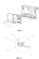
- box body 1 supporting frame 2, first flanging 21, main body portion 22, mounting location 221, second screw thread hole 222, upper mounting plate 3, rotation shaft 31, fixing portion 311, connecting plate 32, second flanging 33, fixing plate 4, first screw thread hole 41, recessed portion 42, and screw bolt 5 are shown.
- an outdoor unit electric cabinet comprising box body 1, two supporting frames 2, upper mounting plate 3, and fixing plate 4.
- Two supporting frames 2 are arranged on inner walls on the opposite sides of box body 1; mounting location 221 is arranged on each supporting frame 2; the opposite sides of upper mounting plate 3 are mounted into mounting location 221 from an entrance of mounting location 221; upper mounting plate 3 is flippable relative to mounting location 221; fixing plate 4 is mounted on the entrance of mounting location 221 to seal the entrance of mounting location 221, so as to prevent upper mounting plate 3 from sliding out from mounting location 221.
- Two supporting frame 2 are respectively arranged on the bottom of inner walls on two sides of box body 1; upper mounting plate 3 is mounted into mounting location 221 of supporting frame 2 from the entrance of mounting location 221, and fixing plate 4 is mounted on the entrance of mounting location 221 to seal the entrance of mounting location 221 and prevent upper mounting plate 3 from sliding out from mounting location 221.
- upper mounting plate 3 can be mounted on box body 1 by means of supporting frames 2 on the bottom of two sides of box body 1.
- upper mounting plate 3 is flippable relative to mounting location 221; therefore, by means of rotating upper mounting plate 3, relative movement occurs between upper mounting plate 3 and box body 1 so as to expose electric elements shielded by upper mounting plate 3 and facilitate maintenance and replacement of electric elements inside the electric cabinet; and it has a simple structure and convenient operation.
- supporting frame 2 comprises main body portion 22 and first flanging 21.
- Main body portion 22 comprises first straight plate 223 and second straight plate 224; first straight plate 223 and second straight plate 224 are fixedly connected to form an angle; second straight plate 224 is bent away from one side of first straight plate 223 to form first flanging 21; main body portion 22 is connected to box body 1 by means of first flanging 21; and an entrance of mounting location 221 is arranged on second straight plate 224.
- first flanging 21 may be provided with assembly holes, and for supporting frame 2, supporting frame 2 may be fixedly assembled to the inner peripheral wall of box body 1 through the assembly holes with threaded connectors.
- supporting frames 2 are arranged on the bottom of inner walls on two sides of box body 1; two sides of upper mounting plates 3 are bent to form second flanging 33; connecting plate 32 is arranged on two ends of the bottom of upper mounting plate 3; connecting plate 32 and second flanging 33 are arranged in a same direction; rotation shaft 31 runs through connecting plate 32 and second flanging 33; fixing portions 311 are arranged on two ends of rotation shaft 31, and a section between fixing portion 311 close to second flanging 33 on rotation shaft 31 and second flanging 33 is mounted on mounting location 221.
- Two supporting frames 2 are arranged on the bottom of inner walls on two sides of box body 1; upper mounting plates 3 are mounted on supporting frame 2 from two ends of the bottom, so as to facilitate that upper mounting plate 3 rotates by taking the bottom side as a shaft.
- Two sides of upper mounting plate 3 are bent to form second flanging 33; second flanging 33 and connecting plate 32 are arranged in a same direction, and rotation shaft 31 penetrates therethrough, so as to make upper mounting plate 3 be capable of flipping when the bottom side is mounted to supporting frame 2.
- Fixing portions 311 are arranged on two ends of rotation shaft 31.
- the area of the cross section connecting fixing portion 311 and rotation shaft 31 is larger than the area of the cross section of rotation shaft 31 so that when rotation shaft 31 penetrates between second flanging 33 and connecting plate 32, it will not fall off connecting plate 32 and second flanging 33.
- the length of rotation shaft 31 is larger than the distance between second flanging 33 and connecting plate 32, so that a gap may be formed between fixing portion 311 close to second flanging 33 and second flanging 33, and a section between fixing portion 311 close to second flanging 33 on rotation shaft 31 and second flanging 33 can be mounted on mounting location 221.
- the mounting manners of two ends on the bottom of upper mounting plate 3 are totally the same, so as to make upper mounting plate 3 be mounted on supporting frame 2.
- mounting location 221 is a U-shaped groove.
- An entrance of mounting location 221 is communicated with the U-shaped groove.
- the longest straight line of a contact surface between fixing portion 311 close to second flanging 33 and first straight plate 223 of main body portion 22 is greater than the width of the U-shaped groove.
- Mounting location 221 is set as a U-shaped groove, so that the end of mounting location 221 can be closer to the curvature of the outer circumference of rotation shaft 31, not damaging rotation shaft 31 during mounting and fixing.
- the longest straight line of a contact surface between fixing portion 311 close to second flanging 33 on rotation shaft 31 and first straight plate 223 of main body portion 22 is greater than the width of the U-shaped groove, so that fixing portion 311 will not penetrate through the U-shaped groove, rotation shaft 31 can be mounted on the U-shaped groove and will not fall off.
- fixing plate 4 is L-shaped; a longitudinal plate of fixing plate 4 is inserted into a gap between first straight plate 223 of main body portion 22 and second flanging 33; first screw thread hole 41 used to fix fixing plate 4 is arranged on a horizontal plate of fixing plate 4; second screw thread hole 222 corresponding to first screw thread hole 41 is further arranged on second straight plate 224 of main body portion 22; fixing plate 4 is sequentially inserted into first screw thread hole 41 and second screw thread hole 222 by means of screw bolt 5 to fix fixing plate 4 on supporting frame 2.
- Fixing plate 4 is set as L-shaped so that fixing plate 4 can fix upper mounting plate 3 on supporting frame 2 when being inserted into the gap.
- First screw thread hole 41 used to fix fixing plate 4 is arranged on a horizontal plate of fixing plate 4;
- second screw thread hole 222 corresponding to first screw thread hole 41 is arranged on second straight plate 224 of main body portion 22; by means of merely rotating screw bolt 5, only first screw thread hole 41 and second screw thread hole 222 may lock fixing plate 4 on supporting frame 2.
- fixing plate 4 is L-shaped, the longitudinal plate thereof is inserted into the gap between second straight plate 224 of main body portion 22 and second flanging 33, and can abut against rotation shaft 31 and prevent it from sliding out. Therefore, by means of fixing plate 4 and screw bolt 5, mounting of upper mounting plate 3 and supporting frame 2 and mounting of fixing plate 4 and supporting frame 2 can be realized.
- recessed portion 42 fit with rotation shaft 31 is arranged on the longitudinal plate of fixing plate 4.
- Recessed portion 42 is arranged, and can fit with the curvature of the outer circumferential surface of rotation shaft 31 when the longitudinal plate of fixing plate 4 is inserted into the gap between second straight plate 224 of main body portion 22 and second flanging 33 to abut against rotation shaft 31, so that rotation shaft 31 is not damaged when the longitudinal plate of fixing plate 4 abuts against rotation shaft 31.
- both the quantity of first screw thread hole 41 and second screw thread hole 222 is two, and two first screw thread holes 41 respectively correspond to two second screw thread holes 222.
- Fixing plate 4 is sequentially inserted into first screw thread hole 41 and second screw thread hole 222 by means of two screw bolts 5 to fix fixing plate 4 on supporting frame 2.
- Two screw thread holes are arranged on second straight plate 224 of main body portions of fixing plate 4 and supporting frame 2.
- Two screw bolts 5 are sequentially inserted into first screw thread hole 41 and second screw thread hole 222 to fix supporting frame 2 and the mounting plate, which is more stable than using single screw bolt 5.
- the recessed portion of the longitudinal plate of fixing plate 4 abuts against rotation shaft 31, and upper mounting plate 3 rotates around rotation shaft 31.
- the longitudinal plate of fixing plate abuts against rotation shaft 31 by means of recessed portion 42, and can clamp rotation shaft 31 between the bottom edge of the longitudinal plate of fixing plate 4 and the bottom of the U-shaped groove.
- the mounting structure of electronically controlled sheet metal components is not compact, which easily causes the components to collide with each other and generate noise. If the length of the longitudinal plate of fixing plate 4 is long enough to abut against rotation shaft 31, so that the edge of the longitudinal plate of fixing plate 4 and the bottom of the U-shaped groove cannot form a large gap, thereby avoiding the collision of rotation shaft 31 moving back and forth in this gap to damage rotation shaft 31, and also avoiding the noise caused by the collision of sheet metal during the transportation of the machine, which is simple for production and maintenance operations and improves efficiency.
- two supporting frames 2 arranged on the upper portion of inner walls on two sides of box body 1 are included.
- Third screw thread hole corresponding to second screw thread hole 222 is arranged on two ends of the upper portion of upper mounting plate 3.
- Upper mounting plate 3 is sequentially inserted into third screw thread hole and second screw thread hole 222 by means of screw bolt 5 to fix upper mounting plate 3 on supporting frames 2 on upper portions of inner walls on two sides of the box body 1.
- Two supporting frames 2 are arranged on the upper portion of inner walls on two sides of box body 1.
- Second screw thread hole 222 is arranged on supporting frame 2.
- Upper mounting plate 3 is rotated to a corresponding position after the maintenance is completed.
- Third screw thread holes on two ends of the upper portion of upper mounting plate 3 are aligned with second screw thread hole 222 on supporting frame 2.
- screw bolt 5 By rotating screw bolt 5 into second screw thread hole 222 and third screw thread hole, the upper portion of upper mounting plate 3 can be mounted on box body 1.
- screw bolts 5 on two ends of the upper portions of upper mounting plate 3 are disassembled, and upper mounting plate 3 is flipped down to facilitate debugging and maintenance of components.
- upper mounting plate 3 is rotated to the initial position, and is fixed by means of the third screw thread hole on the upper portion of upper mounting plate 3. The operation is simple.
- An air conditioner can be provided, where the air conditioner includes the above outdoor unit electric cabinet.
- upper mounting plate 3 when being mounted, debugged, and maintained, electronically controlled upper mounting plate 3 does not need to be disassembled.
- rotation shaft 31 opening, closing, and mounting of upper mounting plate 3 of the electric cabinet is convenient and fast.
- upper mounting plate 3 rotates around rotation shaft 31 and flips up and down. After mounting, debugging and maintenance are completed, it is fixed through the screw thread holes on the upper portions of upper mounting plate 3 to ensure that four corners of upper mounting plate 3 are fixed.
- Fixing plate 4 clamps rotation shaft 31 to avoid the noise caused by the collision of sheet metal during the transportation and operation of the machine, and the production and maintenance operations are simple, and the efficiency is improved.
Landscapes
- Engineering & Computer Science (AREA)
- Chemical & Material Sciences (AREA)
- Combustion & Propulsion (AREA)
- Mechanical Engineering (AREA)
- General Engineering & Computer Science (AREA)
- Casings For Electric Apparatus (AREA)
- Air Filters, Heat-Exchange Apparatuses, And Housings Of Air-Conditioning Units (AREA)
Claims (10)
- Außeneinheitsschaltschrank, umfassend einen Kastenkörper (1), eine obere Montageplatte (3) und eine Befestigungsplatte (4); wobei die obere Montageplatte (3) klappbar ist; gekennzeichnet durch: zwei Trägerrahmen (2), wobei die zwei Trägerrahmen (2) auf Innenwänden an den gegenüberliegenden Seiten des Kastenkörpers (1) angeordnet sind; eine Montagestelle (221) auf jedem Trägerrahmen (2) angeordnet ist; die gegenüberliegenden Seiten der oberen Montageplatte (3) in die Montagestelle (221) von einem Eingang der Montagestelle (221) aus montiert sind; wobei die obere Montageplatte (3) relativ zu der Montagestelle (221) klappbar ist; die Befestigungsplatte (4) an dem Eingang der Montagestelle (221) montiert ist, um den Eingang der Montagestelle (221) zu verschließen, um zu verhindern, dass die obere Montageplatte (3) aus der Montagestelle (221) herausrutscht.
- Außeneinheitsschaltschrank nach Anspruch 1, wobei der Trägerrahmen (2) einen Hauptkörperabschnitt (22) und eine erste Bördelung (21) umfasst, der Hauptkörperabschnitt (22) eine erste gerade Platte (223) und eine zweite gerade Platte (224) umfasst; die erste gerade Platte (223) und die zweite gerade Platte (224) fest verbunden sind, um einen Winkel zu bilden; die zweite gerade Platte (224) von einer Seite der ersten geraden Platte (223) weggebogen ist, um die erste Bördelung (21) zu bilden; der Hauptkörperabschnitt (22) mit dem Kastenkörper (1) mittels der ersten Bördelung (21) verbunden ist; und der Eingang der Montagestelle (21) auf der zweiten geraden Platte (224) angeordnet ist.
- Außeneinheitsschaltschrank nach Anspruch 2, wobei die Trägerrahmen (2) auf dem unteren Teil der Innenwände auf zwei Seiten des Kastenkörpers (2) angeordnet sind;zwei Seiten der oberen Montageplatte (3) gebogen sind, um die zweite Bördelung (33) zu bilden; eine Verbindungsplatte (32) auf zwei Enden des unteren Teils der oberen Montageplatte (3) angeordnet ist; die Verbindungsplatte (32) und die zweite Bördelung (33) in derselben Richtung angeordnet sind; und ein Drehschaft (31) durch die Verbindungsplatte (32) und die zweite Bördelung (33) verläuft; undBefestigungsabschnitte (311) auf zwei Enden des Drehschafts (31) angeordnet sind und ein Abschnitt zwischen einem Befestigungsabschnitt (311) nahe der zweiten Bördelung (33) auf dem Drehschaft (31) und der zweiten Bördelung (33) auf dem Montageabschnitt (221) montiert ist.
- Außeneinheitsschaltschrank nach Anspruch 3, wobei die Montagestelle (221) eine U-förmige Nut ist; der Eingang der Montagestelle (221) mit der U-förmigen Nut in Verbindung steht; und die längste gerade Linie einer Kontaktfläche zwischen dem Befestigungsabschnitt (311) nahe der zweiten Bördelung (33) und der ersten geraden Platte (223) größer ist als die Breite der U-förmigen Nut.
- Außeneinheitsschaltschrank nach Anspruch 3 oder 4, wobei die Befestigungsplatte (4) L-förmig ist; eine Längsplatte der Befestigungsplatte (4) in einen Spalt zwischen der ersten geraden Platte (223) und der zweiten Bördelung (33) eingesetzt ist; und ein erstes Schraubgewindeloch (41), das zum Befestigen der Befestigungsplatte (4) verwendet wird, auf einer horizontalen Platte der Befestigungsplatte (4) angeordnet ist; und
ein zweites Schraubgewindeloch (222), das dem ersten Schraubgewindeloch (41) entspricht, ferner auf der zweiten geraden Platte (224) angeordnet ist; die Befestigungsplatte (4) nacheinander in das erste Schraubgewindeloch (41) und das zweite Schraubgewindeloch (222) mittels eines Schraubbolzens (5) eingesetzt ist, um die Befestigungsplatte (4) auf dem Trägerrahmen (2) zu befestigen. - Außeneinheitsschaltschrank nach Anspruch 5, wobei ein vertiefter Abschnitt (42), der mit dem Drehschaft (31) zusammenpasst, auf der Längsplatte der Befestigungsplatte (4) angeordnet ist.
- Außeneinheitsschaltschrank nach Anspruch 5 oder 6, wobei sowohl die Anzahl der ersten Schraubgewindelöcher (41) als auch die Anzahl der zweiten Schraubgewindelöcher (222) zwei beträgt und die zwei ersten Schraubgewindelöcher (41) jeweils den zwei zweiten Schraubgewindelöchern (222) entsprechen; die Befestigungsplatte (4) nacheinander in die ersten Schraubgewindelöcher (41) und die zweiten Schraubgewindelöcher (22) mittels zweier Schraubenbolzen (5) eingesetzt ist, um die Befestigungsplatte (4) auf dem Trägerrahmen (2) zu befestigen.
- Außeneinheitsschaltschrank nach einem der Ansprüche 5 bis 7, wobei der vertiefte Abschnitt der Längsplatte der Befestigungsplatte (4) an dem Drehschaft (31) anliegt und die obere Montageplatte (3) um den Drehschaft (31) herum klappt.
- Außeneinheitsschaltschrank nach einem der Ansprüche 5 bis 8, ferner umfassend zwei Trägerrahmen (2), die auf oberen Abschnitten von Innenwänden auf zwei Seiten des Kastenkörpers (1) angeordnet sind; wobei ein drittes Schraubgewindeloch, das dem zweiten Schraubgewindeloch (222) entspricht, auf zwei Enden des oberen Abschnitts der oberen Montageplatte (3) angeordnet ist; die obere Montageplatte (3) nacheinander in das dritte Schraubgewindeloch und das zweite Schraubgewindeloch (222) mittels eines Schraubbolzens (5) eingesetzt ist, um die obere Montageplatte (3) auf den Trägerrahmen (2) auf oberen Abschnitten von Innenwänden auf zwei Seiten des Kastenkörpers (1) zu befestigen.
- Klimaanlage, umfassend einen Außeneinheitsschaltschrank nach einem der vorhergehenden Ansprüche.
Applications Claiming Priority (1)
| Application Number | Priority Date | Filing Date | Title |
|---|---|---|---|
| CN202022732283.2U CN213811077U (zh) | 2020-11-23 | 2020-11-23 | 室外机电控箱及具有其的空调器 |
Publications (2)
| Publication Number | Publication Date |
|---|---|
| EP4001782A1 EP4001782A1 (de) | 2022-05-25 |
| EP4001782B1 true EP4001782B1 (de) | 2025-02-12 |
Family
ID=76937407
Family Applications (1)
| Application Number | Title | Priority Date | Filing Date |
|---|---|---|---|
| EP21209485.8A Active EP4001782B1 (de) | 2020-11-23 | 2021-11-22 | Ausseneinheitschaltschrank und klimaanlage mit ausseneinheitschaltschrank |
Country Status (4)
| Country | Link |
|---|---|
| US (1) | US12228296B2 (de) |
| EP (1) | EP4001782B1 (de) |
| CN (1) | CN213811077U (de) |
| ES (1) | ES3013812T3 (de) |
Families Citing this family (2)
| Publication number | Priority date | Publication date | Assignee | Title |
|---|---|---|---|---|
| CN116481091B (zh) * | 2023-04-13 | 2025-10-03 | 武汉赫岩科技股份有限公司 | 一种快装式设备悬挂支撑装置及其施工方法 |
| KR20250009307A (ko) * | 2023-07-10 | 2025-01-17 | 삼성전자주식회사 | 공기조화기의 실외기 |
Family Cites Families (7)
| Publication number | Priority date | Publication date | Assignee | Title |
|---|---|---|---|---|
| JPH07318110A (ja) | 1994-05-20 | 1995-12-08 | Fujitsu General Ltd | 空気調和機の室外機 |
| JPWO2007108447A1 (ja) * | 2006-03-17 | 2009-08-06 | 東芝キヤリア株式会社 | 空気調和装置の室外ユニット |
| JP5569417B2 (ja) * | 2011-01-31 | 2014-08-13 | 株式会社富士通ゼネラル | 空気調和機の室外機 |
| KR102168620B1 (ko) * | 2014-02-03 | 2020-10-21 | 엘지전자 주식회사 | 공기조화기의 실외기 |
| JP2019049388A (ja) | 2017-09-11 | 2019-03-28 | 三菱重工サーマルシステムズ株式会社 | コントロールボックス |
| JP6674668B2 (ja) * | 2018-01-26 | 2020-04-01 | 株式会社富士通ゼネラル | 電装品モジュール |
| CN208029239U (zh) | 2018-03-23 | 2018-10-30 | 奥克斯空调股份有限公司 | 电控盒结构及壁挂式空调器 |
-
2020
- 2020-11-23 CN CN202022732283.2U patent/CN213811077U/zh active Active
-
2021
- 2021-11-22 US US17/532,241 patent/US12228296B2/en active Active
- 2021-11-22 EP EP21209485.8A patent/EP4001782B1/de active Active
- 2021-11-22 ES ES21209485T patent/ES3013812T3/es active Active
Also Published As
| Publication number | Publication date |
|---|---|
| ES3013812T3 (en) | 2025-04-15 |
| US20220163222A1 (en) | 2022-05-26 |
| CN213811077U (zh) | 2021-07-27 |
| EP4001782A1 (de) | 2022-05-25 |
| US12228296B2 (en) | 2025-02-18 |
Similar Documents
| Publication | Publication Date | Title |
|---|---|---|
| EP4001782B1 (de) | Ausseneinheitschaltschrank und klimaanlage mit ausseneinheitschaltschrank | |
| US5402323A (en) | Equipment cabinet having spring-elastic seals | |
| US11432429B2 (en) | Adjustable barrier for enclosures | |
| CN216836630U (zh) | 电梯控制柜 | |
| US20130104344A1 (en) | Hinge-mounted door stop | |
| KR20160003412U (ko) | 철재 랙 캐비넷 조립체 | |
| CN217882463U (zh) | 一种带有配电箱安装架的配电箱 | |
| CN220769174U (zh) | 一种中间铰链组件及具有其的蒸烤箱 | |
| US7425026B1 (en) | Seismic-resistant equipment cabinets and door latches | |
| JP2001274565A (ja) | ドア枠体及び収納体 | |
| US6115885A (en) | Twisted hinge | |
| CN219779515U (zh) | 一种前后开门的核电厂电源机柜 | |
| JPH06309859A (ja) | ハードディスク取付装置 | |
| CN221278245U (zh) | 一种铰接结构 | |
| CN223678494U (zh) | 一种保护沉降观测标的组合式保护盒 | |
| CN217841252U (zh) | 一种长跨度的门轴机构 | |
| CN223089129U (zh) | 模块化超薄家具铰链底盘系统及铰链 | |
| CN220711476U (zh) | 无线数据传输终端 | |
| CN222745903U (zh) | 免干涉隐藏式铰链结构和专用铰链固定块和利用其的家具 | |
| CN221000246U (zh) | 铰链组件及安装设备 | |
| CN212908608U (zh) | 开关柜用柜门及具有其的开关柜 | |
| CN218782745U (zh) | 一种显示屏箱体及显示屏 | |
| CN220119550U (zh) | 一种柜机进风口密封机构及柜机 | |
| CN220528354U (zh) | 一种防护装置及通风设备 | |
| CN216866349U (zh) | 一种内铰链及采用内铰链的门结构 |
Legal Events
| Date | Code | Title | Description |
|---|---|---|---|
| PUAI | Public reference made under article 153(3) epc to a published international application that has entered the european phase |
Free format text: ORIGINAL CODE: 0009012 |
|
| STAA | Information on the status of an ep patent application or granted ep patent |
Free format text: STATUS: THE APPLICATION HAS BEEN PUBLISHED |
|
| AK | Designated contracting states |
Kind code of ref document: A1 Designated state(s): AL AT BE BG CH CY CZ DE DK EE ES FI FR GB GR HR HU IE IS IT LI LT LU LV MC MK MT NL NO PL PT RO RS SE SI SK SM TR |
|
| STAA | Information on the status of an ep patent application or granted ep patent |
Free format text: STATUS: REQUEST FOR EXAMINATION WAS MADE |
|
| 17P | Request for examination filed |
Effective date: 20221111 |
|
| RBV | Designated contracting states (corrected) |
Designated state(s): AL AT BE BG CH CY CZ DE DK EE ES FI FR GB GR HR HU IE IS IT LI LT LU LV MC MK MT NL NO PL PT RO RS SE SI SK SM TR |
|
| P01 | Opt-out of the competence of the unified patent court (upc) registered |
Effective date: 20230527 |
|
| GRAP | Despatch of communication of intention to grant a patent |
Free format text: ORIGINAL CODE: EPIDOSNIGR1 |
|
| STAA | Information on the status of an ep patent application or granted ep patent |
Free format text: STATUS: GRANT OF PATENT IS INTENDED |
|
| INTG | Intention to grant announced |
Effective date: 20241024 |
|
| GRAS | Grant fee paid |
Free format text: ORIGINAL CODE: EPIDOSNIGR3 |
|
| GRAA | (expected) grant |
Free format text: ORIGINAL CODE: 0009210 |
|
| STAA | Information on the status of an ep patent application or granted ep patent |
Free format text: STATUS: THE PATENT HAS BEEN GRANTED |
|
| AK | Designated contracting states |
Kind code of ref document: B1 Designated state(s): AL AT BE BG CH CY CZ DE DK EE ES FI FR GB GR HR HU IE IS IT LI LT LU LV MC MK MT NL NO PL PT RO RS SE SI SK SM TR |
|
| REG | Reference to a national code |
Ref country code: GB Ref legal event code: FG4D |
|
| REG | Reference to a national code |
Ref country code: CH Ref legal event code: EP |
|
| REG | Reference to a national code |
Ref country code: DE Ref legal event code: R096 Ref document number: 602021025932 Country of ref document: DE |
|
| REG | Reference to a national code |
Ref country code: IE Ref legal event code: FG4D |
|
| REG | Reference to a national code |
Ref country code: ES Ref legal event code: FG2A Ref document number: 3013812 Country of ref document: ES Kind code of ref document: T3 Effective date: 20250415 |
|
| REG | Reference to a national code |
Ref country code: NL Ref legal event code: MP Effective date: 20250212 |
|
| PG25 | Lapsed in a contracting state [announced via postgrant information from national office to epo] |
Ref country code: RS Free format text: LAPSE BECAUSE OF FAILURE TO SUBMIT A TRANSLATION OF THE DESCRIPTION OR TO PAY THE FEE WITHIN THE PRESCRIBED TIME-LIMIT Effective date: 20250512 |
|
| PG25 | Lapsed in a contracting state [announced via postgrant information from national office to epo] |
Ref country code: FI Free format text: LAPSE BECAUSE OF FAILURE TO SUBMIT A TRANSLATION OF THE DESCRIPTION OR TO PAY THE FEE WITHIN THE PRESCRIBED TIME-LIMIT Effective date: 20250212 |
|
| PG25 | Lapsed in a contracting state [announced via postgrant information from national office to epo] |
Ref country code: PL Free format text: LAPSE BECAUSE OF FAILURE TO SUBMIT A TRANSLATION OF THE DESCRIPTION OR TO PAY THE FEE WITHIN THE PRESCRIBED TIME-LIMIT Effective date: 20250212 |
|
| REG | Reference to a national code |
Ref country code: LT Ref legal event code: MG9D |
|
| PG25 | Lapsed in a contracting state [announced via postgrant information from national office to epo] |
Ref country code: NO Free format text: LAPSE BECAUSE OF FAILURE TO SUBMIT A TRANSLATION OF THE DESCRIPTION OR TO PAY THE FEE WITHIN THE PRESCRIBED TIME-LIMIT Effective date: 20250512 Ref country code: IS Free format text: LAPSE BECAUSE OF FAILURE TO SUBMIT A TRANSLATION OF THE DESCRIPTION OR TO PAY THE FEE WITHIN THE PRESCRIBED TIME-LIMIT Effective date: 20250612 |
|
| PG25 | Lapsed in a contracting state [announced via postgrant information from national office to epo] |
Ref country code: NL Free format text: LAPSE BECAUSE OF FAILURE TO SUBMIT A TRANSLATION OF THE DESCRIPTION OR TO PAY THE FEE WITHIN THE PRESCRIBED TIME-LIMIT Effective date: 20250212 |
|
| PG25 | Lapsed in a contracting state [announced via postgrant information from national office to epo] |
Ref country code: HR Free format text: LAPSE BECAUSE OF FAILURE TO SUBMIT A TRANSLATION OF THE DESCRIPTION OR TO PAY THE FEE WITHIN THE PRESCRIBED TIME-LIMIT Effective date: 20250212 |
|
| PG25 | Lapsed in a contracting state [announced via postgrant information from national office to epo] |
Ref country code: LV Free format text: LAPSE BECAUSE OF FAILURE TO SUBMIT A TRANSLATION OF THE DESCRIPTION OR TO PAY THE FEE WITHIN THE PRESCRIBED TIME-LIMIT Effective date: 20250212 Ref country code: PT Free format text: LAPSE BECAUSE OF FAILURE TO SUBMIT A TRANSLATION OF THE DESCRIPTION OR TO PAY THE FEE WITHIN THE PRESCRIBED TIME-LIMIT Effective date: 20250612 |
|
| PG25 | Lapsed in a contracting state [announced via postgrant information from national office to epo] |
Ref country code: GR Free format text: LAPSE BECAUSE OF FAILURE TO SUBMIT A TRANSLATION OF THE DESCRIPTION OR TO PAY THE FEE WITHIN THE PRESCRIBED TIME-LIMIT Effective date: 20250513 Ref country code: BG Free format text: LAPSE BECAUSE OF FAILURE TO SUBMIT A TRANSLATION OF THE DESCRIPTION OR TO PAY THE FEE WITHIN THE PRESCRIBED TIME-LIMIT Effective date: 20250212 |
|
| REG | Reference to a national code |
Ref country code: AT Ref legal event code: MK05 Ref document number: 1766346 Country of ref document: AT Kind code of ref document: T Effective date: 20250212 |
|
| PG25 | Lapsed in a contracting state [announced via postgrant information from national office to epo] |
Ref country code: SE Free format text: LAPSE BECAUSE OF FAILURE TO SUBMIT A TRANSLATION OF THE DESCRIPTION OR TO PAY THE FEE WITHIN THE PRESCRIBED TIME-LIMIT Effective date: 20250212 |
|
| PG25 | Lapsed in a contracting state [announced via postgrant information from national office to epo] |
Ref country code: SM Free format text: LAPSE BECAUSE OF FAILURE TO SUBMIT A TRANSLATION OF THE DESCRIPTION OR TO PAY THE FEE WITHIN THE PRESCRIBED TIME-LIMIT Effective date: 20250212 |
|
| PG25 | Lapsed in a contracting state [announced via postgrant information from national office to epo] |
Ref country code: DK Free format text: LAPSE BECAUSE OF FAILURE TO SUBMIT A TRANSLATION OF THE DESCRIPTION OR TO PAY THE FEE WITHIN THE PRESCRIBED TIME-LIMIT Effective date: 20250212 |
|
| PG25 | Lapsed in a contracting state [announced via postgrant information from national office to epo] |
Ref country code: IT Free format text: LAPSE BECAUSE OF FAILURE TO SUBMIT A TRANSLATION OF THE DESCRIPTION OR TO PAY THE FEE WITHIN THE PRESCRIBED TIME-LIMIT Effective date: 20250212 |
|
| PG25 | Lapsed in a contracting state [announced via postgrant information from national office to epo] |
Ref country code: AT Free format text: LAPSE BECAUSE OF FAILURE TO SUBMIT A TRANSLATION OF THE DESCRIPTION OR TO PAY THE FEE WITHIN THE PRESCRIBED TIME-LIMIT Effective date: 20250212 |
|
| PG25 | Lapsed in a contracting state [announced via postgrant information from national office to epo] |
Ref country code: EE Free format text: LAPSE BECAUSE OF FAILURE TO SUBMIT A TRANSLATION OF THE DESCRIPTION OR TO PAY THE FEE WITHIN THE PRESCRIBED TIME-LIMIT Effective date: 20250212 Ref country code: CZ Free format text: LAPSE BECAUSE OF FAILURE TO SUBMIT A TRANSLATION OF THE DESCRIPTION OR TO PAY THE FEE WITHIN THE PRESCRIBED TIME-LIMIT Effective date: 20250212 |
|
| PG25 | Lapsed in a contracting state [announced via postgrant information from national office to epo] |
Ref country code: RO Free format text: LAPSE BECAUSE OF FAILURE TO SUBMIT A TRANSLATION OF THE DESCRIPTION OR TO PAY THE FEE WITHIN THE PRESCRIBED TIME-LIMIT Effective date: 20250212 |
|
| PG25 | Lapsed in a contracting state [announced via postgrant information from national office to epo] |
Ref country code: SK Free format text: LAPSE BECAUSE OF FAILURE TO SUBMIT A TRANSLATION OF THE DESCRIPTION OR TO PAY THE FEE WITHIN THE PRESCRIBED TIME-LIMIT Effective date: 20250212 |
|
| REG | Reference to a national code |
Ref country code: DE Ref legal event code: R097 Ref document number: 602021025932 Country of ref document: DE |
|
| PLBE | No opposition filed within time limit |
Free format text: ORIGINAL CODE: 0009261 |
|
| STAA | Information on the status of an ep patent application or granted ep patent |
Free format text: STATUS: NO OPPOSITION FILED WITHIN TIME LIMIT |
|
| PGFP | Annual fee paid to national office [announced via postgrant information from national office to epo] |
Ref country code: DE Payment date: 20251022 Year of fee payment: 5 |
|
| PGFP | Annual fee paid to national office [announced via postgrant information from national office to epo] |
Ref country code: FR Payment date: 20251022 Year of fee payment: 5 |
|
| 26N | No opposition filed |
Effective date: 20251113 |
|
| PGFP | Annual fee paid to national office [announced via postgrant information from national office to epo] |
Ref country code: ES Payment date: 20251201 Year of fee payment: 5 |