EP4001806B1 - Kühlschrank - Google Patents
Kühlschrank Download PDFInfo
- Publication number
- EP4001806B1 EP4001806B1 EP20841219.7A EP20841219A EP4001806B1 EP 4001806 B1 EP4001806 B1 EP 4001806B1 EP 20841219 A EP20841219 A EP 20841219A EP 4001806 B1 EP4001806 B1 EP 4001806B1
- Authority
- EP
- European Patent Office
- Prior art keywords
- air
- disposed
- evaporator
- drying
- opening
- Prior art date
- Legal status (The legal status is an assumption and is not a legal conclusion. Google has not performed a legal analysis and makes no representation as to the accuracy of the status listed.)
- Active
Links
Images

Classifications
-
- F—MECHANICAL ENGINEERING; LIGHTING; HEATING; WEAPONS; BLASTING
- F25—REFRIGERATION OR COOLING; COMBINED HEATING AND REFRIGERATION SYSTEMS; HEAT PUMP SYSTEMS; MANUFACTURE OR STORAGE OF ICE; LIQUEFACTION SOLIDIFICATION OF GASES
- F25D—REFRIGERATORS; COLD ROOMS; ICE-BOXES; COOLING OR FREEZING APPARATUS NOT OTHERWISE PROVIDED FOR
- F25D17/00—Arrangements for circulating cooling fluids; Arrangements for circulating gas, e.g. air, within refrigerated spaces
- F25D17/04—Arrangements for circulating cooling fluids; Arrangements for circulating gas, e.g. air, within refrigerated spaces for circulating air, e.g. by convection
- F25D17/042—Air treating means within refrigerated spaces
-
- F—MECHANICAL ENGINEERING; LIGHTING; HEATING; WEAPONS; BLASTING
- F25—REFRIGERATION OR COOLING; COMBINED HEATING AND REFRIGERATION SYSTEMS; HEAT PUMP SYSTEMS; MANUFACTURE OR STORAGE OF ICE; LIQUEFACTION SOLIDIFICATION OF GASES
- F25D—REFRIGERATORS; COLD ROOMS; ICE-BOXES; COOLING OR FREEZING APPARATUS NOT OTHERWISE PROVIDED FOR
- F25D17/00—Arrangements for circulating cooling fluids; Arrangements for circulating gas, e.g. air, within refrigerated spaces
- F25D17/04—Arrangements for circulating cooling fluids; Arrangements for circulating gas, e.g. air, within refrigerated spaces for circulating air, e.g. by convection
- F25D17/06—Arrangements for circulating cooling fluids; Arrangements for circulating gas, e.g. air, within refrigerated spaces for circulating air, e.g. by convection by forced circulation
- F25D17/062—Arrangements for circulating cooling fluids; Arrangements for circulating gas, e.g. air, within refrigerated spaces for circulating air, e.g. by convection by forced circulation in household refrigerators
-
- F—MECHANICAL ENGINEERING; LIGHTING; HEATING; WEAPONS; BLASTING
- F25—REFRIGERATION OR COOLING; COMBINED HEATING AND REFRIGERATION SYSTEMS; HEAT PUMP SYSTEMS; MANUFACTURE OR STORAGE OF ICE; LIQUEFACTION SOLIDIFICATION OF GASES
- F25D—REFRIGERATORS; COLD ROOMS; ICE-BOXES; COOLING OR FREEZING APPARATUS NOT OTHERWISE PROVIDED FOR
- F25D21/00—Defrosting; Preventing frosting; Removing condensed or defrost water
- F25D21/04—Preventing the formation of frost or condensate
-
- F—MECHANICAL ENGINEERING; LIGHTING; HEATING; WEAPONS; BLASTING
- F25—REFRIGERATION OR COOLING; COMBINED HEATING AND REFRIGERATION SYSTEMS; HEAT PUMP SYSTEMS; MANUFACTURE OR STORAGE OF ICE; LIQUEFACTION SOLIDIFICATION OF GASES
- F25D—REFRIGERATORS; COLD ROOMS; ICE-BOXES; COOLING OR FREEZING APPARATUS NOT OTHERWISE PROVIDED FOR
- F25D21/00—Defrosting; Preventing frosting; Removing condensed or defrost water
- F25D21/14—Collecting or removing condensed and defrost water; Drip trays
-
- F—MECHANICAL ENGINEERING; LIGHTING; HEATING; WEAPONS; BLASTING
- F25—REFRIGERATION OR COOLING; COMBINED HEATING AND REFRIGERATION SYSTEMS; HEAT PUMP SYSTEMS; MANUFACTURE OR STORAGE OF ICE; LIQUEFACTION SOLIDIFICATION OF GASES
- F25D—REFRIGERATORS; COLD ROOMS; ICE-BOXES; COOLING OR FREEZING APPARATUS NOT OTHERWISE PROVIDED FOR
- F25D23/00—General constructional features
- F25D23/006—General constructional features for mounting refrigerating machinery components
-
- F—MECHANICAL ENGINEERING; LIGHTING; HEATING; WEAPONS; BLASTING
- F25—REFRIGERATION OR COOLING; COMBINED HEATING AND REFRIGERATION SYSTEMS; HEAT PUMP SYSTEMS; MANUFACTURE OR STORAGE OF ICE; LIQUEFACTION SOLIDIFICATION OF GASES
- F25D—REFRIGERATORS; COLD ROOMS; ICE-BOXES; COOLING OR FREEZING APPARATUS NOT OTHERWISE PROVIDED FOR
- F25D2317/00—Details or arrangements for circulating cooling fluids; Details or arrangements for circulating gas, e.g. air, within refrigerated spaces, not provided for in other groups of this subclass
- F25D2317/04—Treating air flowing to refrigeration compartments
- F25D2317/041—Treating air flowing to refrigeration compartments by purification
- F25D2317/0411—Treating air flowing to refrigeration compartments by purification by dehumidification
-
- F—MECHANICAL ENGINEERING; LIGHTING; HEATING; WEAPONS; BLASTING
- F25—REFRIGERATION OR COOLING; COMBINED HEATING AND REFRIGERATION SYSTEMS; HEAT PUMP SYSTEMS; MANUFACTURE OR STORAGE OF ICE; LIQUEFACTION SOLIDIFICATION OF GASES
- F25D—REFRIGERATORS; COLD ROOMS; ICE-BOXES; COOLING OR FREEZING APPARATUS NOT OTHERWISE PROVIDED FOR
- F25D2317/00—Details or arrangements for circulating cooling fluids; Details or arrangements for circulating gas, e.g. air, within refrigerated spaces, not provided for in other groups of this subclass
- F25D2317/04—Treating air flowing to refrigeration compartments
- F25D2317/041—Treating air flowing to refrigeration compartments by purification
- F25D2317/0415—Treating air flowing to refrigeration compartments by purification by deodorizing
-
- F—MECHANICAL ENGINEERING; LIGHTING; HEATING; WEAPONS; BLASTING
- F25—REFRIGERATION OR COOLING; COMBINED HEATING AND REFRIGERATION SYSTEMS; HEAT PUMP SYSTEMS; MANUFACTURE OR STORAGE OF ICE; LIQUEFACTION SOLIDIFICATION OF GASES
- F25D—REFRIGERATORS; COLD ROOMS; ICE-BOXES; COOLING OR FREEZING APPARATUS NOT OTHERWISE PROVIDED FOR
- F25D2317/00—Details or arrangements for circulating cooling fluids; Details or arrangements for circulating gas, e.g. air, within refrigerated spaces, not provided for in other groups of this subclass
- F25D2317/06—Details or arrangements for circulating cooling fluids; Details or arrangements for circulating gas, e.g. air, within refrigerated spaces, not provided for in other groups of this subclass with forced air circulation
- F25D2317/067—Details or arrangements for circulating cooling fluids; Details or arrangements for circulating gas, e.g. air, within refrigerated spaces, not provided for in other groups of this subclass with forced air circulation characterised by air ducts
- F25D2317/0671—Inlet ducts
-
- F—MECHANICAL ENGINEERING; LIGHTING; HEATING; WEAPONS; BLASTING
- F25—REFRIGERATION OR COOLING; COMBINED HEATING AND REFRIGERATION SYSTEMS; HEAT PUMP SYSTEMS; MANUFACTURE OR STORAGE OF ICE; LIQUEFACTION SOLIDIFICATION OF GASES
- F25D—REFRIGERATORS; COLD ROOMS; ICE-BOXES; COOLING OR FREEZING APPARATUS NOT OTHERWISE PROVIDED FOR
- F25D2317/00—Details or arrangements for circulating cooling fluids; Details or arrangements for circulating gas, e.g. air, within refrigerated spaces, not provided for in other groups of this subclass
- F25D2317/06—Details or arrangements for circulating cooling fluids; Details or arrangements for circulating gas, e.g. air, within refrigerated spaces, not provided for in other groups of this subclass with forced air circulation
- F25D2317/067—Details or arrangements for circulating cooling fluids; Details or arrangements for circulating gas, e.g. air, within refrigerated spaces, not provided for in other groups of this subclass with forced air circulation characterised by air ducts
- F25D2317/0672—Outlet ducts
Definitions
- the present invention relates to the field of refrigeration appliance and particularly to an air duct system and a refrigeration appliance having the same.
- JPS4980959U relates to a refrigerating device having a drying device.
- JP2008122064A relates to an evaporator of a refrigerating machine.
- JP2014180608A relates to a method of manufacturing cooler and heat exchanger of compressed air dehumidifier.
- a defrosting heater is disposed nearby the evaporator and heats the frost on the evaporator to defrost. This defrosting manner is less efficient, increases the freezing load of the refrigerator, and finally reduces the cooling efficiency of the refrigerator.
- the present invention provides an air duct system avoiding frosting on the evaporator and a refrigeration appliance having the same.
- the invention also provides a refrigeration appliance having any of the said air duct system above, the refrigeration appliance comprises a cabinet having a refrigeration compartment, the air duct system is disposed on the cabinet and used to supply cool to the refrigeration compartment, and the air return port and the air supply port are disposed on an inner wall of the refrigeration compartment.
- the drying system and the cooling system are arranged in cooperation with each other, so that the air discharged through the air return port sequentially passes through the air compressor and the air storage tank, and then flows to the evaporator so that the air passing through the evaporator is dried, thereby avoiding the frosting phenomenon, omitting the defrosting process, and avoiding problems such as the increase of the load and low efficiency.
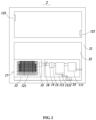
- the present invention provides an air duct system 1 for supplying cold air to a refrigeration compartment.
- the air duct system 1 comprises a drying system 11 and a cooling system 12 which are arranged in cooperation with each other.
- the cooling system 12 comprises an evaporator 121, and an air return port 122 and an air supply port 123 provided on two sides of the evaporator 121, and the drying system 11 is disposed between the air return port 122 and the evaporator 121 so that the air flowing towards the evaporator 121 is dried, thereby avoiding the frosting phenomenon.
- the cooling system 12 is provided with a cooling chamber 15, and the evaporator 121 is disposed in the cooling chamber 15.
- the said cooling chamber 15 is usually enclosed by a thermal insulating material; in the present embodiment, the drying system 11 is disposed outside the cooling chamber 15, and supplies dried air to the cooling chamber 15, thereby reducing the space occupied by the cooling chamber 15 so that the drying system 11 may utilize other external space which don't need to be thermally insulated.
- the drying system 11 may also be disposed in the cooling chamber 15.
- the cooling chamber 15 has a first opening 151 connected to the drying system 11 and a second opening 152 connected to the air supply port 123.
- the first opening 151 and the second opening 152 are respectively located on two sides of the evaporator 121, so that the dry air discharged from the drying system 11 enters the cooling chamber 15 through the first opening 151, then flows to the evaporator 121, and then is discharged out of the air supply port 123 through the second opening 152.
- the air duct system 1 further comprises a first check valve 16 disposed at the first opening 151, and a second check valve 16 disposed at the second opening 152 or the air supply port 123; the first check valve 16 is capable of preventing reverse flow of air discharged from the drying system 11, and the second check valve 17 is capable of preventing reverse flow of air discharged from the air supply port 123.
- the drying system 11 comprises an air compressor 111 and an air storage tank 112 that are connected to each other, so that the air discharged through the air return port 122 sequentially flows through the air compressor 111, the air storage tank 112 and then to the evaporator 121.
- the air compressor 111 draws and compresses air from the air return port 122 to reduce the saturation of water vapor, so that most of the water vapor in the air storage tank 112 is condensed into water, in order to dry the air passing through the evaporator 121, avoiding the frosting phenomenon, omitting the defrosting process, and avoiding problems such as the increase of the load and low efficiency.
- the bottom of the air storage tank 112 is provided with a drainage outlet 1121 and a water drainage valve 1122 connected to the drainage outlet 1121, so that the condensed water is discharged to the external through the water drainage valve 1122.
- the air duct system 1 of the present invention is further provided with at least one drying module 13.
- the drying module 13 is disposed between the air storage tank 112 and the evaporator 121 to further dry the air, ensure that the air discharged to the evaporator 121 is dry air and avoid frosting on the evaporator 121.
- FIG. 1 there are two said drying module 13, one of which is disposed close to the air storage tank 112, and the other is disposed close to the evaporator 121, so that the air after being discharged from the air storage tank 112 flows through the drying module 13 and then to the evaporator 121.
- the two drying modules can further dry the air.
- the drying module 13 disposed close to the evaporator 121 is disposed in the first opening 151 or disposed adjacent to the first opening 151.
- the drying module 13 disposed close to the air storage tank 112 is directly disposed at an output end 1123 of the air storage tank 112.
- the air duct system 1 further comprises at least one deodorizing module 14.
- at least one deodorizing module 14 is disposed between the air storage tank 112 and the first opening 151 to remove the odor in the air.
- the deodorizing module 14 may also be disposed between the evaporator 121 and the air supply port 123, so that the air discharged from the air supply port 123 is free of the odor.
- the drying system 11 in order to facilitate an operation such as installation, is provided with a drying compartment 18, and the air compressor 111 and the air storage tank 112 are both disposed in the drying compartment 18. However, the drying system 11 is still connected the air compressor 111 and the air return port 122 through a pipeline or air duct, and the drying system 11 is communicated with the cooling chamber 15 through a pipeline or air duct.
- the air compressor 111 and the air storage tank 112 may also be set to an open type, which facilitates the heat dissipation of the air compressor 111.
- the present invention further provides a refrigeration appliance 2 having any air duct system 1 as described above.
- the refrigeration appliance 2 comprises a cabinet 21 having a refrigeration compartment 22, the air duct system 1 is disposed on the cabinet 21 and used to supply cool to the refrigeration compartment 22, and the air return port 122 and the air supply port 123 are disposed on the inner wall of the refrigeration compartment 22, so that the air in the refrigeration compartment 22, after being discharged through the air return port 122, is sequentially dried through the air compressor 111 and the air storage tank 112, then flows to the evaporator 121 for cooling, then is discharged through the air supply port 123 to the refrigeration compartment 22, so that the air passing through the evaporator 121 is dried, thereby avoiding the frosting phenomenon, omitting the defrosting process and improving the cooling efficiency of the refrigeration appliance 2.
- the refrigeration appliance 2 further comprises a water collecting box 23 arranged in the cabinet 21, and the drainage outlet 1121 of the air storage tank 112 is connected with the water collecting box 23, thereby preventing water from flowing to the external and causing possible safety hazards, and meanwhile improving the heat dissipation efficiency of the refrigeration appliance 2.
- the drying system 11 and the cooling system 12 are arranged in cooperation with each other, so that the air discharged through the air return port 122 sequentially passes through the air compressor 111 and the air storage tank 112, and then flows to the evaporator 121 so that the air passing through the evaporator 121 is dried, thereby avoiding the frosting phenomenon, omitting the defrosting process, and avoiding problems such as the increase of the load and low efficiency.
Landscapes
- Engineering & Computer Science (AREA)
- Chemical & Material Sciences (AREA)
- Combustion & Propulsion (AREA)
- Physics & Mathematics (AREA)
- Mechanical Engineering (AREA)
- Thermal Sciences (AREA)
- General Engineering & Computer Science (AREA)
- Cold Air Circulating Systems And Constructional Details In Refrigerators (AREA)
- Removal Of Water From Condensation And Defrosting (AREA)
- Detail Structures Of Washing Machines And Dryers (AREA)
Claims (5)
- Luftkanalsystem (1), wobei das Luftkanalsystem (1) ein Trocknungssystem (11) und ein Kühlsystem (12) umfasst, die zusammenwirkend angeordnet sind, wobei das Kühlsystem (12) einen Verdampfer (121) und eine Luftrückführöffnung (122) und eine Luftzuführungsöffnung (123) umfasst, die auf zwei Seiten des Verdampfers (121) vorgesehen sind, das Trocknungssystem (11) zwischen der Luftrückführöffnung (122) und dem Verdampfer (121) angeordnet ist, und das Trocknungssystem (11) einen Luftkompressor (111) und einen Luftspeicherbehälter (112) umfasst, die miteinander verbunden sind, sodass die durch die Luftrückführöffnung (122) abgegebene Luft nacheinander durch den Luftkompressor (111) und den Luftspeicherbehälter (112) und dann zum Verdampfer (121) strömt;dadurch gekennzeichnet, dass das Kühlsystem (12) eine Kühlkammer (15) zur Aufnahme des Verdampfers (121) umfasst und die Kühlkammer (15) eine erste Öffnung (151), die mit dem Trocknungssystem (11) verbunden ist, und eine zweite Öffnung (152), die mit der Luftzuführungsöffnung (123) verbunden ist, umfasst; wobei die erste Öffnung (151) und die zweite Öffnung (152) jeweils auf zwei Seiten des Verdampfers (121) angeordnet sind; undwobei das Luftkanalsystem (1) ferner zwei Trocknungsmodule (13) umfasst, die zwischen dem Luftspeicherbehälter (112) und dem Verdampfer (121) angeordnet sind; wobei ein Trocknungsmodul (13) in der ersten Öffnung (151) oder angrenzend an die erste Öffnung (151) angeordnet ist und das andere in dem Trocknungssystem (11) angeordnet ist und sich an einem Ausgangsende des Luftspeicherbehälters (112) befindet;wobei das Luftkanalsystem (1) ein erstes Rückschlagventil (16), das an der ersten Öffnung (151) angeordnet ist, und ein zweites Rückschlagventil (17) umfasst, das an der zweiten Öffnung (152) oder der Luftzuführungsöffnung (123) angeordnet ist.
- Luftkanalsystem (1) nach Anspruch 1, wobei ein Boden des Luftspeicherbehälters (112) mit einer Abflussöffnung (1121) und einem mit der Abflussöffnung (1121) verbundenen Wasserablassventil (1122) versehen ist.
- Luftkanalsystem (1) nach Anspruch 1, wobei das Luftkanalsystem (1) ferner ein Desodorierungsmodul (14) umfasst, das zwischen dem Luftspeicherbehälter (112) und der ersten Öffnung (151) angeordnet ist.
- Luftkanalsystem (1) nach Anspruch 1, wobei das Trocknungssystem (11) mit einer Trocknungskammer (18) versehen ist und der Luftkompressor (111) und der Luftspeicherbehälter (112) beide in der Trocknungskammer (18) angeordnet sind.
- Kühlgerät (2) mit dem Luftkanalsystem (1) nach einem der Ansprüche 1 bis 4, wobei das Kühlgerät (2) ein Gehäuse (21) mit einem Kühlfach (22) aufweist, das Luftkanalsystem (1) an dem Gehäuse (21) angeordnet ist und dazu verwendet wird, dem Kühlfach (22) Kühlung zuzuführen, und die Luftrückführöffnung (122) und die Luftzuführungsöffnung (123) an einer Innenwand des Kühlfachs (22) angeordnet sind.
Applications Claiming Priority (2)
| Application Number | Priority Date | Filing Date | Title |
|---|---|---|---|
| CN201910647038.0A CN112240673B (zh) | 2019-07-17 | 2019-07-17 | 风道系统及具有其的制冷设备 |
| PCT/CN2020/077546 WO2021008140A1 (zh) | 2019-07-17 | 2020-03-03 | 冰箱 |
Publications (3)
| Publication Number | Publication Date |
|---|---|
| EP4001806A1 EP4001806A1 (de) | 2022-05-25 |
| EP4001806A4 EP4001806A4 (de) | 2022-08-31 |
| EP4001806B1 true EP4001806B1 (de) | 2024-12-04 |
Family
ID=74167400
Family Applications (1)
| Application Number | Title | Priority Date | Filing Date |
|---|---|---|---|
| EP20841219.7A Active EP4001806B1 (de) | 2019-07-17 | 2020-03-03 | Kühlschrank |
Country Status (5)
| Country | Link |
|---|---|
| US (1) | US11920850B2 (de) |
| EP (1) | EP4001806B1 (de) |
| CN (1) | CN112240673B (de) |
| AU (1) | AU2020314014B2 (de) |
| WO (1) | WO2021008140A1 (de) |
Family Cites Families (20)
| Publication number | Priority date | Publication date | Assignee | Title |
|---|---|---|---|---|
| US2143188A (en) * | 1935-12-06 | 1939-01-10 | Toledo Scale Mfg Co | Refrigeration |
| JPS4980959U (de) * | 1972-10-30 | 1974-07-12 | ||
| DD293320A5 (de) * | 1990-04-05 | 1991-08-29 | Handelshochschule Leipzig,De | Verpackung mit feuchtereguliertem kryptoklima und verfahren zu ihrer herstellung |
| KR960010662B1 (ko) * | 1993-05-12 | 1996-08-07 | 엘지전자 주식회사 | 냉장고 |
| KR20000020426A (ko) * | 1998-09-21 | 2000-04-15 | 전주범 | 다공 착상판을 이용한 냉장고 제습장치 |
| US7665314B2 (en) * | 2005-10-31 | 2010-02-23 | Carrier Corporation | Intermodal air compressor water separator and heat exchanger |
| JP2008122064A (ja) * | 2006-10-20 | 2008-05-29 | Isamu Kuramoto | 霜着き防止冷凍機および冷凍機の除霜装置 |
| KR20110100086A (ko) * | 2010-03-03 | 2011-09-09 | (주)보광훼미리마트 | 제상수 집수증발장치 |
| CN102116557A (zh) * | 2011-03-31 | 2011-07-06 | 合肥美的荣事达电冰箱有限公司 | 用于冰箱的风冷循环系统和具有其的风冷冰箱 |
| DE102011050691A1 (de) * | 2011-05-27 | 2012-11-29 | WISAG Gebäude- und Industrieservice Mitteldeutschland GmbH & Co. KG | Vorrichtung und Verfahren zur Einstellung der Luftfeuchte in Kühlräumen |
| CN202326234U (zh) * | 2011-09-09 | 2012-07-11 | 湖南云箭集团有限公司 | 一种全性能涡旋空气压缩机一体机 |
| US9834192B2 (en) * | 2013-03-05 | 2017-12-05 | Haldex Brake Products Corporation | Automatic air tank purge system |
| JP2014180608A (ja) * | 2013-03-19 | 2014-09-29 | Orion Mach Co Ltd | 冷却器の製造方法および圧縮空気除湿装置の熱交換器 |
| CN104406350B (zh) * | 2014-12-02 | 2016-10-05 | 合肥美的电冰箱有限公司 | 一种冰箱用风冷循环蒸发器系统及冰箱 |
| CN104880000A (zh) * | 2015-05-15 | 2015-09-02 | 郑州亨利制冷设备有限公司 | 一种速冻装置用蒸发器空气除霜系统 |
| CN106288593A (zh) * | 2015-05-29 | 2017-01-04 | 青岛海尔智能技术研发有限公司 | 冰箱 |
| CN105928290A (zh) * | 2016-04-25 | 2016-09-07 | 江苏大学 | 一种基于吸附抑霜技术的风冷冰箱制冷系统 |
| CN108870833B (zh) * | 2017-05-11 | 2020-07-03 | 合肥华凌股份有限公司 | 一种冰箱 |
| CN109990527A (zh) * | 2017-12-29 | 2019-07-09 | 青岛海尔股份有限公司 | 一种具有门体干燥室的冰箱 |
| CN108534427A (zh) * | 2018-04-13 | 2018-09-14 | 宁波得晴电器科技有限公司 | 一种家用电器 |
-
2019
- 2019-07-17 CN CN201910647038.0A patent/CN112240673B/zh active Active
-
2020
- 2020-03-03 EP EP20841219.7A patent/EP4001806B1/de active Active
- 2020-03-03 WO PCT/CN2020/077546 patent/WO2021008140A1/zh not_active Ceased
- 2020-03-03 US US17/615,829 patent/US11920850B2/en active Active
- 2020-03-03 AU AU2020314014A patent/AU2020314014B2/en active Active
Also Published As
| Publication number | Publication date |
|---|---|
| EP4001806A4 (de) | 2022-08-31 |
| CN112240673B (zh) | 2022-05-20 |
| CN112240673A (zh) | 2021-01-19 |
| US11920850B2 (en) | 2024-03-05 |
| US20220325939A1 (en) | 2022-10-13 |
| AU2020314014A1 (en) | 2021-12-23 |
| EP4001806A1 (de) | 2022-05-25 |
| WO2021008140A1 (zh) | 2021-01-21 |
| AU2020314014B2 (en) | 2023-02-16 |
Similar Documents
| Publication | Publication Date | Title |
|---|---|---|
| WO2018121593A1 (zh) | 冰箱节能制冷系统及具有该系统的冰箱运行方法 | |
| CN206113475U (zh) | 一种风冷冰箱的除霜系统和风冷冰箱 | |
| KR101536819B1 (ko) | 열펌프 건조기 | |
| KR20060089752A (ko) | 냉각고 | |
| CN112460903A (zh) | 制冷化霜系统及制冷设备 | |
| WO2021258819A1 (zh) | 冰箱 | |
| CN203203293U (zh) | 空气源热泵制冷制热系统 | |
| CN108036569A (zh) | 一种风干冰箱及其控制方法 | |
| US9328952B2 (en) | Refrigerating machine having tube-cooled evaporator and air-cooled evaporator | |
| EP4001806B1 (de) | Kühlschrank | |
| CN113758134B (zh) | 冰箱的控制方法及冰箱 | |
| JP2004324902A (ja) | 冷凍冷蔵庫 | |
| CN217979466U (zh) | 一种风冷冷柜的整体式排水结构 | |
| JP2004333092A (ja) | 冷凍冷蔵庫 | |
| WO2015165512A1 (en) | Refrigeration appliance having an anti-condensation arrangement | |
| KR101788095B1 (ko) | 냉각기용 열교환기의 성에제거 장치 | |
| AU2013227989B1 (en) | Refrigerating Machine | |
| JP2709890B2 (ja) | 冷却装置 | |
| KR20100124490A (ko) | 히트펌프방식을 이용한 냉온전환식 건조기 | |
| CN208504838U (zh) | 一种风干冰箱 | |
| WO2015149840A1 (en) | Refrigeration appliance provided with an improved defrost circuit | |
| EP3175184B1 (de) | Kältevorrichtung mit abtaukreislauf für tiefkühlerverdampfer | |
| CN220624579U (zh) | 冷热柜 | |
| CN215638171U (zh) | 风冷冰箱 | |
| KR100210055B1 (ko) | 냉매를 이용한 냉장고의 제상구조 |
Legal Events
| Date | Code | Title | Description |
|---|---|---|---|
| STAA | Information on the status of an ep patent application or granted ep patent |
Free format text: STATUS: THE INTERNATIONAL PUBLICATION HAS BEEN MADE |
|
| PUAI | Public reference made under article 153(3) epc to a published international application that has entered the european phase |
Free format text: ORIGINAL CODE: 0009012 |
|
| STAA | Information on the status of an ep patent application or granted ep patent |
Free format text: STATUS: REQUEST FOR EXAMINATION WAS MADE |
|
| 17P | Request for examination filed |
Effective date: 20220114 |
|
| AK | Designated contracting states |
Kind code of ref document: A1 Designated state(s): AL AT BE BG CH CY CZ DE DK EE ES FI FR GB GR HR HU IE IS IT LI LT LU LV MC MK MT NL NO PL PT RO RS SE SI SK SM TR |
|
| A4 | Supplementary search report drawn up and despatched |
Effective date: 20220729 |
|
| RIC1 | Information provided on ipc code assigned before grant |
Ipc: F25D 17/04 20060101ALI20220725BHEP Ipc: F25D 21/04 20060101AFI20220725BHEP |
|
| DAV | Request for validation of the european patent (deleted) | ||
| DAX | Request for extension of the european patent (deleted) | ||
| GRAP | Despatch of communication of intention to grant a patent |
Free format text: ORIGINAL CODE: EPIDOSNIGR1 |
|
| STAA | Information on the status of an ep patent application or granted ep patent |
Free format text: STATUS: GRANT OF PATENT IS INTENDED |
|
| RIC1 | Information provided on ipc code assigned before grant |
Ipc: F25D 17/04 20060101ALI20240606BHEP Ipc: F25D 21/04 20060101AFI20240606BHEP |
|
| GRAJ | Information related to disapproval of communication of intention to grant by the applicant or resumption of examination proceedings by the epo deleted |
Free format text: ORIGINAL CODE: EPIDOSDIGR1 |
|
| STAA | Information on the status of an ep patent application or granted ep patent |
Free format text: STATUS: REQUEST FOR EXAMINATION WAS MADE |
|
| INTG | Intention to grant announced |
Effective date: 20240708 |
|
| INTC | Intention to grant announced (deleted) | ||
| GRAP | Despatch of communication of intention to grant a patent |
Free format text: ORIGINAL CODE: EPIDOSNIGR1 |
|
| STAA | Information on the status of an ep patent application or granted ep patent |
Free format text: STATUS: GRANT OF PATENT IS INTENDED |
|
| INTG | Intention to grant announced |
Effective date: 20240913 |
|
| GRAS | Grant fee paid |
Free format text: ORIGINAL CODE: EPIDOSNIGR3 |
|
| GRAA | (expected) grant |
Free format text: ORIGINAL CODE: 0009210 |
|
| STAA | Information on the status of an ep patent application or granted ep patent |
Free format text: STATUS: THE PATENT HAS BEEN GRANTED |
|
| AK | Designated contracting states |
Kind code of ref document: B1 Designated state(s): AL AT BE BG CH CY CZ DE DK EE ES FI FR GB GR HR HU IE IS IT LI LT LU LV MC MK MT NL NO PL PT RO RS SE SI SK SM TR |
|
| REG | Reference to a national code |
Ref country code: CH Ref legal event code: EP |
|
| REG | Reference to a national code |
Ref country code: DE Ref legal event code: R096 Ref document number: 602020042682 Country of ref document: DE |
|
| REG | Reference to a national code |
Ref country code: IE Ref legal event code: FG4D |
|
| REG | Reference to a national code |
Ref country code: LT Ref legal event code: MG9D |
|
| REG | Reference to a national code |
Ref country code: NL Ref legal event code: MP Effective date: 20241204 |
|
| PG25 | Lapsed in a contracting state [announced via postgrant information from national office to epo] |
Ref country code: HR Free format text: LAPSE BECAUSE OF FAILURE TO SUBMIT A TRANSLATION OF THE DESCRIPTION OR TO PAY THE FEE WITHIN THE PRESCRIBED TIME-LIMIT Effective date: 20241204 |
|
| PG25 | Lapsed in a contracting state [announced via postgrant information from national office to epo] |
Ref country code: FI Free format text: LAPSE BECAUSE OF FAILURE TO SUBMIT A TRANSLATION OF THE DESCRIPTION OR TO PAY THE FEE WITHIN THE PRESCRIBED TIME-LIMIT Effective date: 20241204 |
|
| PG25 | Lapsed in a contracting state [announced via postgrant information from national office to epo] |
Ref country code: BG Free format text: LAPSE BECAUSE OF FAILURE TO SUBMIT A TRANSLATION OF THE DESCRIPTION OR TO PAY THE FEE WITHIN THE PRESCRIBED TIME-LIMIT Effective date: 20241204 |
|
| PG25 | Lapsed in a contracting state [announced via postgrant information from national office to epo] |
Ref country code: ES Free format text: LAPSE BECAUSE OF FAILURE TO SUBMIT A TRANSLATION OF THE DESCRIPTION OR TO PAY THE FEE WITHIN THE PRESCRIBED TIME-LIMIT Effective date: 20241204 |
|
| PG25 | Lapsed in a contracting state [announced via postgrant information from national office to epo] |
Ref country code: NO Free format text: LAPSE BECAUSE OF FAILURE TO SUBMIT A TRANSLATION OF THE DESCRIPTION OR TO PAY THE FEE WITHIN THE PRESCRIBED TIME-LIMIT Effective date: 20250304 |
|
| PG25 | Lapsed in a contracting state [announced via postgrant information from national office to epo] |
Ref country code: LV Free format text: LAPSE BECAUSE OF FAILURE TO SUBMIT A TRANSLATION OF THE DESCRIPTION OR TO PAY THE FEE WITHIN THE PRESCRIBED TIME-LIMIT Effective date: 20241204 Ref country code: GR Free format text: LAPSE BECAUSE OF FAILURE TO SUBMIT A TRANSLATION OF THE DESCRIPTION OR TO PAY THE FEE WITHIN THE PRESCRIBED TIME-LIMIT Effective date: 20250305 |
|
| PG25 | Lapsed in a contracting state [announced via postgrant information from national office to epo] |
Ref country code: RS Free format text: LAPSE BECAUSE OF FAILURE TO SUBMIT A TRANSLATION OF THE DESCRIPTION OR TO PAY THE FEE WITHIN THE PRESCRIBED TIME-LIMIT Effective date: 20250304 |
|
| PG25 | Lapsed in a contracting state [announced via postgrant information from national office to epo] |
Ref country code: NL Free format text: LAPSE BECAUSE OF FAILURE TO SUBMIT A TRANSLATION OF THE DESCRIPTION OR TO PAY THE FEE WITHIN THE PRESCRIBED TIME-LIMIT Effective date: 20241204 |
|
| REG | Reference to a national code |
Ref country code: AT Ref legal event code: MK05 Ref document number: 1748575 Country of ref document: AT Kind code of ref document: T Effective date: 20241204 |
|
| PG25 | Lapsed in a contracting state [announced via postgrant information from national office to epo] |
Ref country code: SM Free format text: LAPSE BECAUSE OF FAILURE TO SUBMIT A TRANSLATION OF THE DESCRIPTION OR TO PAY THE FEE WITHIN THE PRESCRIBED TIME-LIMIT Effective date: 20241204 |
|
| PG25 | Lapsed in a contracting state [announced via postgrant information from national office to epo] |
Ref country code: PL Free format text: LAPSE BECAUSE OF FAILURE TO SUBMIT A TRANSLATION OF THE DESCRIPTION OR TO PAY THE FEE WITHIN THE PRESCRIBED TIME-LIMIT Effective date: 20241204 |
|
| PG25 | Lapsed in a contracting state [announced via postgrant information from national office to epo] |
Ref country code: IS Free format text: LAPSE BECAUSE OF FAILURE TO SUBMIT A TRANSLATION OF THE DESCRIPTION OR TO PAY THE FEE WITHIN THE PRESCRIBED TIME-LIMIT Effective date: 20250404 |
|
| PG25 | Lapsed in a contracting state [announced via postgrant information from national office to epo] |
Ref country code: PT Free format text: LAPSE BECAUSE OF FAILURE TO SUBMIT A TRANSLATION OF THE DESCRIPTION OR TO PAY THE FEE WITHIN THE PRESCRIBED TIME-LIMIT Effective date: 20250404 |
|
| PG25 | Lapsed in a contracting state [announced via postgrant information from national office to epo] |
Ref country code: EE Free format text: LAPSE BECAUSE OF FAILURE TO SUBMIT A TRANSLATION OF THE DESCRIPTION OR TO PAY THE FEE WITHIN THE PRESCRIBED TIME-LIMIT Effective date: 20241204 |
|
| PG25 | Lapsed in a contracting state [announced via postgrant information from national office to epo] |
Ref country code: AT Free format text: LAPSE BECAUSE OF FAILURE TO SUBMIT A TRANSLATION OF THE DESCRIPTION OR TO PAY THE FEE WITHIN THE PRESCRIBED TIME-LIMIT Effective date: 20241204 Ref country code: RO Free format text: LAPSE BECAUSE OF FAILURE TO SUBMIT A TRANSLATION OF THE DESCRIPTION OR TO PAY THE FEE WITHIN THE PRESCRIBED TIME-LIMIT Effective date: 20241204 |
|
| PG25 | Lapsed in a contracting state [announced via postgrant information from national office to epo] |
Ref country code: SK Free format text: LAPSE BECAUSE OF FAILURE TO SUBMIT A TRANSLATION OF THE DESCRIPTION OR TO PAY THE FEE WITHIN THE PRESCRIBED TIME-LIMIT Effective date: 20241204 |
|
| PG25 | Lapsed in a contracting state [announced via postgrant information from national office to epo] |
Ref country code: CZ Free format text: LAPSE BECAUSE OF FAILURE TO SUBMIT A TRANSLATION OF THE DESCRIPTION OR TO PAY THE FEE WITHIN THE PRESCRIBED TIME-LIMIT Effective date: 20241204 |
|
| PG25 | Lapsed in a contracting state [announced via postgrant information from national office to epo] |
Ref country code: IT Free format text: LAPSE BECAUSE OF FAILURE TO SUBMIT A TRANSLATION OF THE DESCRIPTION OR TO PAY THE FEE WITHIN THE PRESCRIBED TIME-LIMIT Effective date: 20241204 |
|
| REG | Reference to a national code |
Ref country code: DE Ref legal event code: R097 Ref document number: 602020042682 Country of ref document: DE |
|
| PG25 | Lapsed in a contracting state [announced via postgrant information from national office to epo] |
Ref country code: SE Free format text: LAPSE BECAUSE OF FAILURE TO SUBMIT A TRANSLATION OF THE DESCRIPTION OR TO PAY THE FEE WITHIN THE PRESCRIBED TIME-LIMIT Effective date: 20241204 |
|
| PG25 | Lapsed in a contracting state [announced via postgrant information from national office to epo] |
Ref country code: DK Free format text: LAPSE BECAUSE OF FAILURE TO SUBMIT A TRANSLATION OF THE DESCRIPTION OR TO PAY THE FEE WITHIN THE PRESCRIBED TIME-LIMIT Effective date: 20241204 |
|
| PLBE | No opposition filed within time limit |
Free format text: ORIGINAL CODE: 0009261 |
|
| STAA | Information on the status of an ep patent application or granted ep patent |
Free format text: STATUS: NO OPPOSITION FILED WITHIN TIME LIMIT |
|
| PG25 | Lapsed in a contracting state [announced via postgrant information from national office to epo] |
Ref country code: MC Free format text: LAPSE BECAUSE OF FAILURE TO SUBMIT A TRANSLATION OF THE DESCRIPTION OR TO PAY THE FEE WITHIN THE PRESCRIBED TIME-LIMIT Effective date: 20241204 |
|
| REG | Reference to a national code |
Ref country code: CH Ref legal event code: L10 Free format text: ST27 STATUS EVENT CODE: U-0-0-L10-L00 (AS PROVIDED BY THE NATIONAL OFFICE) Effective date: 20251015 |
|
| REG | Reference to a national code |
Ref country code: CH Ref legal event code: H13 Free format text: ST27 STATUS EVENT CODE: U-0-0-H10-H13 (AS PROVIDED BY THE NATIONAL OFFICE) Effective date: 20251023 |
|
| 26N | No opposition filed |
Effective date: 20250905 |
|
| PG25 | Lapsed in a contracting state [announced via postgrant information from national office to epo] |
Ref country code: LU Free format text: LAPSE BECAUSE OF NON-PAYMENT OF DUE FEES Effective date: 20250303 |
|
| REG | Reference to a national code |
Ref country code: BE Ref legal event code: MM Effective date: 20250331 |
|
| PG25 | Lapsed in a contracting state [announced via postgrant information from national office to epo] |
Ref country code: BE Free format text: LAPSE BECAUSE OF NON-PAYMENT OF DUE FEES Effective date: 20250331 |
|
| PG25 | Lapsed in a contracting state [announced via postgrant information from national office to epo] |
Ref country code: CH Free format text: LAPSE BECAUSE OF NON-PAYMENT OF DUE FEES Effective date: 20250331 |
|
| PG25 | Lapsed in a contracting state [announced via postgrant information from national office to epo] |
Ref country code: IE Free format text: LAPSE BECAUSE OF NON-PAYMENT OF DUE FEES Effective date: 20250303 |
|
| PGFP | Annual fee paid to national office [announced via postgrant information from national office to epo] |
Ref country code: GB Payment date: 20260323 Year of fee payment: 7 |
|
| PGFP | Annual fee paid to national office [announced via postgrant information from national office to epo] |
Ref country code: DE Payment date: 20260313 Year of fee payment: 7 |
|
| PGFP | Annual fee paid to national office [announced via postgrant information from national office to epo] |
Ref country code: FR Payment date: 20260330 Year of fee payment: 7 |