EP4001815A1 - Elektrodentrocknungsvorrichtung mit einem wasserzufuhrteil und verfahren zum trocknen einer elektrode damit - Google Patents
Elektrodentrocknungsvorrichtung mit einem wasserzufuhrteil und verfahren zum trocknen einer elektrode damit Download PDFInfo
- Publication number
- EP4001815A1 EP4001815A1 EP20847966.7A EP20847966A EP4001815A1 EP 4001815 A1 EP4001815 A1 EP 4001815A1 EP 20847966 A EP20847966 A EP 20847966A EP 4001815 A1 EP4001815 A1 EP 4001815A1
- Authority
- EP
- European Patent Office
- Prior art keywords
- accommodation space
- electrode
- moisture
- supply unit
- drying apparatus
- Prior art date
- Legal status (The legal status is an assumption and is not a legal conclusion. Google has not performed a legal analysis and makes no representation as to the accuracy of the status listed.)
- Granted
Links
Images


Classifications
-
- F—MECHANICAL ENGINEERING; LIGHTING; HEATING; WEAPONS; BLASTING
- F26—DRYING
- F26B—DRYING SOLID MATERIALS OR OBJECTS BY REMOVING LIQUID THEREFROM
- F26B21/00—Arrangements for supplying or controlling air or other gases for drying solid materials or objects
- F26B21/40—Arrangements for supplying or controlling air or other gases for drying solid materials or objects using gases other than air
- F26B21/45—Arrangements for supplying or controlling air or other gases for drying solid materials or objects using gases other than air using steam
- F26B21/452—Arrangements for supplying or controlling air or other gases for drying solid materials or objects using gases other than air using steam characterised by the steam generating means
-
- F—MECHANICAL ENGINEERING; LIGHTING; HEATING; WEAPONS; BLASTING
- F26—DRYING
- F26B—DRYING SOLID MATERIALS OR OBJECTS BY REMOVING LIQUID THEREFROM
- F26B13/00—Machines and apparatus for drying fabrics, fibres, yarns, or other materials in long lengths, with progressive movement
-
- F—MECHANICAL ENGINEERING; LIGHTING; HEATING; WEAPONS; BLASTING
- F26—DRYING
- F26B—DRYING SOLID MATERIALS OR OBJECTS BY REMOVING LIQUID THEREFROM
- F26B13/00—Machines and apparatus for drying fabrics, fibres, yarns, or other materials in long lengths, with progressive movement
- F26B13/10—Arrangements for feeding, heating or supporting materials; Controlling movement, tension or position of materials
- F26B13/101—Supporting materials without tension, e.g. on or between foraminous belts
- F26B13/104—Supporting materials without tension, e.g. on or between foraminous belts supported by fluid jets only; Fluid blowing arrangements for flotation dryers, e.g. coanda nozzles
-
- F—MECHANICAL ENGINEERING; LIGHTING; HEATING; WEAPONS; BLASTING
- F26—DRYING
- F26B—DRYING SOLID MATERIALS OR OBJECTS BY REMOVING LIQUID THEREFROM
- F26B13/00—Machines and apparatus for drying fabrics, fibres, yarns, or other materials in long lengths, with progressive movement
- F26B13/10—Arrangements for feeding, heating or supporting materials; Controlling movement, tension or position of materials
- F26B13/12—Controlling movement, tension or position of material
-
- F—MECHANICAL ENGINEERING; LIGHTING; HEATING; WEAPONS; BLASTING
- F26—DRYING
- F26B—DRYING SOLID MATERIALS OR OBJECTS BY REMOVING LIQUID THEREFROM
- F26B15/00—Machines or apparatus for drying objects with progressive movement; Machines or apparatus with progressive movement for drying batches of material in compact form
- F26B15/10—Machines or apparatus for drying objects with progressive movement; Machines or apparatus with progressive movement for drying batches of material in compact form with movement in a path composed of one or more straight lines, e.g. compound, the movement being in alternate horizontal and vertical directions
- F26B15/12—Machines or apparatus for drying objects with progressive movement; Machines or apparatus with progressive movement for drying batches of material in compact form with movement in a path composed of one or more straight lines, e.g. compound, the movement being in alternate horizontal and vertical directions the lines being all horizontal or slightly inclined
-
- F—MECHANICAL ENGINEERING; LIGHTING; HEATING; WEAPONS; BLASTING
- F26—DRYING
- F26B—DRYING SOLID MATERIALS OR OBJECTS BY REMOVING LIQUID THEREFROM
- F26B21/00—Arrangements for supplying or controlling air or other gases for drying solid materials or objects
- F26B21/001—Air generating units, e.g. movable or independent of drying enclosure
- F26B21/002—Air generating units, e.g. movable or independent of drying enclosure with means for indirect air heating, i.e. using heat exchangers
-
- F—MECHANICAL ENGINEERING; LIGHTING; HEATING; WEAPONS; BLASTING
- F26—DRYING
- F26B—DRYING SOLID MATERIALS OR OBJECTS BY REMOVING LIQUID THEREFROM
- F26B21/00—Arrangements for supplying or controlling air or other gases for drying solid materials or objects
- F26B21/003—Air or gas filters
-
- F—MECHANICAL ENGINEERING; LIGHTING; HEATING; WEAPONS; BLASTING
- F26—DRYING
- F26B—DRYING SOLID MATERIALS OR OBJECTS BY REMOVING LIQUID THEREFROM
- F26B21/00—Arrangements for supplying or controlling air or other gases for drying solid materials or objects
- F26B21/30—Controlling, e.g. regulating, parameters of gas supply
- F26B21/33—Humidity
-
- F—MECHANICAL ENGINEERING; LIGHTING; HEATING; WEAPONS; BLASTING
- F26—DRYING
- F26B—DRYING SOLID MATERIALS OR OBJECTS BY REMOVING LIQUID THEREFROM
- F26B21/00—Arrangements for supplying or controlling air or other gases for drying solid materials or objects
- F26B21/30—Controlling, e.g. regulating, parameters of gas supply
- F26B21/35—Temperature; Pressure
-
- F—MECHANICAL ENGINEERING; LIGHTING; HEATING; WEAPONS; BLASTING
- F26—DRYING
- F26B—DRYING SOLID MATERIALS OR OBJECTS BY REMOVING LIQUID THEREFROM
- F26B21/00—Arrangements for supplying or controlling air or other gases for drying solid materials or objects
- F26B21/30—Controlling, e.g. regulating, parameters of gas supply
- F26B21/37—Velocity of flow; Quantity of flow
-
- F—MECHANICAL ENGINEERING; LIGHTING; HEATING; WEAPONS; BLASTING
- F26—DRYING
- F26B—DRYING SOLID MATERIALS OR OBJECTS BY REMOVING LIQUID THEREFROM
- F26B21/00—Arrangements for supplying or controlling air or other gases for drying solid materials or objects
- F26B21/50—Ducting arrangements from the source of air or other gases to the materials or objects being dried
-
- F—MECHANICAL ENGINEERING; LIGHTING; HEATING; WEAPONS; BLASTING
- F26—DRYING
- F26B—DRYING SOLID MATERIALS OR OBJECTS BY REMOVING LIQUID THEREFROM
- F26B3/00—Drying solid materials or objects by processes involving the application of heat
- F26B3/02—Drying solid materials or objects by processes involving the application of heat by convection, i.e. heat being conveyed from a heat source to the materials or objects to be dried by a gas or vapour, e.g. air
- F26B3/04—Drying solid materials or objects by processes involving the application of heat by convection, i.e. heat being conveyed from a heat source to the materials or objects to be dried by a gas or vapour, e.g. air the gas or vapour circulating over or surrounding the materials or objects to be dried
-
- F—MECHANICAL ENGINEERING; LIGHTING; HEATING; WEAPONS; BLASTING
- F26—DRYING
- F26B—DRYING SOLID MATERIALS OR OBJECTS BY REMOVING LIQUID THEREFROM
- F26B3/00—Drying solid materials or objects by processes involving the application of heat
- F26B3/02—Drying solid materials or objects by processes involving the application of heat by convection, i.e. heat being conveyed from a heat source to the materials or objects to be dried by a gas or vapour, e.g. air
- F26B3/10—Drying solid materials or objects by processes involving the application of heat by convection, i.e. heat being conveyed from a heat source to the materials or objects to be dried by a gas or vapour, e.g. air the gas or vapour carrying the materials or objects to be dried with it
- F26B3/12—Drying solid materials or objects by processes involving the application of heat by convection, i.e. heat being conveyed from a heat source to the materials or objects to be dried by a gas or vapour, e.g. air the gas or vapour carrying the materials or objects to be dried with it in the form of a spray, i.e. sprayed or dispersed emulsions or suspensions
-
- H—ELECTRICITY
- H01—ELECTRIC ELEMENTS
- H01M—PROCESSES OR MEANS, e.g. BATTERIES, FOR THE DIRECT CONVERSION OF CHEMICAL ENERGY INTO ELECTRICAL ENERGY
- H01M4/00—Electrodes
- H01M4/02—Electrodes composed of, or comprising, active material
- H01M4/04—Processes of manufacture in general
- H01M4/0471—Processes of manufacture in general involving thermal treatment, e.g. firing, sintering, backing particulate active material, thermal decomposition, pyrolysis
-
- H—ELECTRICITY
- H01—ELECTRIC ELEMENTS
- H01M—PROCESSES OR MEANS, e.g. BATTERIES, FOR THE DIRECT CONVERSION OF CHEMICAL ENERGY INTO ELECTRICAL ENERGY
- H01M4/00—Electrodes
- H01M4/02—Electrodes composed of, or comprising, active material
- H01M4/13—Electrodes for accumulators with non-aqueous electrolyte, e.g. for lithium-accumulators; Processes of manufacture thereof
- H01M4/139—Processes of manufacture
-
- Y—GENERAL TAGGING OF NEW TECHNOLOGICAL DEVELOPMENTS; GENERAL TAGGING OF CROSS-SECTIONAL TECHNOLOGIES SPANNING OVER SEVERAL SECTIONS OF THE IPC; TECHNICAL SUBJECTS COVERED BY FORMER USPC CROSS-REFERENCE ART COLLECTIONS [XRACs] AND DIGESTS
- Y02—TECHNOLOGIES OR APPLICATIONS FOR MITIGATION OR ADAPTATION AGAINST CLIMATE CHANGE
- Y02E—REDUCTION OF GREENHOUSE GAS [GHG] EMISSIONS, RELATED TO ENERGY GENERATION, TRANSMISSION OR DISTRIBUTION
- Y02E60/00—Enabling technologies; Technologies with a potential or indirect contribution to GHG emissions mitigation
- Y02E60/10—Energy storage using batteries
Definitions
- the present invention relates to an electrode drying apparatus and an electrode drying method using the same and, more particularly, to an electrode drying apparatus including a moisture supply unit able to stabilize the internal temperature of a drying oven when drying an electrode using hot air and an electrode drying method using the same.
- lithium secondary cells respectively include a positive electrode, a negative electrode, and an electrolyte interposed between the negative electrode and the positive electrode.
- Lithium secondary cells are divided into lithium ion cells, lithium polymer cells, and the like, depending on which one of a positive electrode active material and a negative electrode active material is used.
- electrodes of such an lithium secondary cell may respectively be formed by coating a current collector, such as a sheet, a mesh, a film, or foil, made of aluminum (Al) or copper (Cu), with a positive electrode or negative electrode active material, followed by drying in a drying oven.
- a current collector such as a sheet, a mesh, a film, or foil, made of aluminum (Al) or copper (Cu)
- Al aluminum
- Cu copper
- a patent application for such a drying process was previously filed as Korean Patent Application Publication No. 10-2012-0057437 (published on June 5, 2012 ).
- the internal temperature of the drying oven is lowered due to evaporation heat of a solvent. Due to the resultant heat loss, after the interior of the oven is thermally stabilized, the temperature of hot air discharged from a hot air nozzle is lower than a set temperature by an average of 5°C to 10°C.
- the actual temperature of the hot air supplied into the oven after the interior of the oven is thermally stabilized by evaporation heat of the solvent may range from 140°C to 145°C.
- electrode drying conditions in the case of mass production are determined on the basis of a state in which the interior of the oven is sufficiently stabilized in terms of drying performance. Such a difference between the temperatures before and after the temperature of the oven is stabilized increases with increases in the amount of the drying solvent.
- the high-speed and high-loading production of electrodes increases the amount of the drying solvent, and also increases the difference between the temperatures before and after the stabilization of the drying oven at the early stage.
- the electrodes may have problems, such as peeling or cracking, caused by over-drying. These problems may cause a decrease in productivity and disconnection during operation of the electrodes, and thus, an improvement is required.
- the present invention has been made to solve the above problems, and an object of the present invention is to propose an electrode drying apparatus including a moisture supply unit capable of setting the internal temperature of a drying oven to a reference value, which is a level at which the drying of an electrode to be dried is stabilized, before an electrode drying process using hot air is started, thereby preventing the electrode from being fractured by over-drying at the early stage of drying the electrode in the drying oven, and an electrode drying method using the same.
- an electrode drying apparatus including: a body including an internal accommodation space provided for a drying process, an inlet, and an outlet; a transportation unit configured to transport an electrode to be dried in a single direction so that the electrode to be dried passes through the accommodation space through the inlet and the outlet; a hot air supply unit configured to blow hot air toward the electrode to be dried transported by the transportation unit so as to dry the electrode to be dried; a temperature measuring unit configured to measure an internal temperature of the accommodation space; a moisture supply unit configured to supply moisture into the accommodation space before the electrode to be dried passes through the accommodation space, so that the internal temperature of the accommodation space is lowered to a predetermined reference value by evaporation heat of the supplied moisture and is stabilized; and a controller configured to control the entire elements disposed within the body.
- the hot air supply unit may include: a heat exchanger configured to heat external air supplied thereto; and a blower fan configured to supply the external air heated by the heat exchanger into the accommodation space.
- the hot air supply unit may further include a damper disposed within a duct that communicates with an interior of the accommodation space and configured to adjust an amount of the hot air supplied into the accommodation space.
- the moisture supply unit may include a moisture spray nozzle disposed within the duct and configured to supply moisture in form of mist so that the moisture is contained in and supplied together with the hot air supplied into the accommodation space.
- a drain hole may be provided in a bottom of the duct, such that water is discharged outwards therethrough when the water leaks from the moisture supply unit.
- the moisture supply unit may include: a storage tank in which ultrapure water (DI water) is stored; and a supply pump configured to supply the ultrapure water stored in the storage tank to the moisture spray nozzle through a supply line.
- DI water ultrapure water
- a plurality of the electrode drying apparatuses are spaced apart from each other in parallel.
- the ultrapure water (DI water) stored in the storage tank may be supplied to each of the plurality of electrode drying apparatuses through the supply line.
- an on-off valve and a flow meter may be disposed on the supply line connected to the electrode drying apparatus, such that the controller monitors and controls, in real time, a total amount of the ultrapure water supplied to the electrode drying apparatus using the on-off valve and the flow meter.
- the temperature measuring unit may include: a first sensor configured to measure the temperature of the hot air supplied by the hot air supply unit; a second sensor configured to monitor the internal temperature of the accommodation space in real time; and a third sensor configured to measure the temperature of air discharged from the accommodation space.
- the controller may control the moisture supply unit to supply the moisture into the accommodation space so that the internal temperature of the accommodation space reaches the reference value.
- an electrode drying method including: measuring an internal temperature of an accommodation space before introducing an electrode to be dried into the accommodation space of an electrode drying apparatus; when the measured internal temperature of the accommodation space is higher than a reference value, which is a level at which drying of the electrode to be dried is stabilized, spraying, by a moisture supply unit, moisture into the accommodation space to cool the accommodation space; determining, by a controller, whether or not the internal temperature of the accommodation space has reached the reference value by evaporation heat of the moisture supplied into the accommodation space; and when the internal temperature of the accommodation space has reached the reference value, stopping the supplying of the moisture into the accommodation space and performing a drying process by allowing the electrode to be dried to move through the accommodation space.
- a reference value which is a level at which drying of the electrode to be dried is stabilized
- the moisture supply unit may allow the moisture to be contained in and supplied together with a hot air supplied into the accommodation space.
- the controller may adjust an amount of the moisture sprayed by the moisture supply unit by comparing a measured temperature of air discharged through the accommodation space with the reference value.
- the present invention having the above-described configuration may measure the internal temperature of the accommodation space before inputting the electrode to be dried into the accommodation space of the electrode drying apparatus, determine whether or not the measured internal temperature of the accommodation space is a level at which the drying of the electrode to be dried is stabilized, and when the measured internal temperature of the accommodation space is higher than the reference value, spray moisture into the accommodation space using the moisture supply unit so as to cool the accommodation space to a temperature corresponding to the level of the reference value.
- the level at which the drying of the electrode to be dried is stabilized may be maintained, thereby preventing the electrode to be dried from being peeled or cracked by over-drying of the electrode at the early stage of the drying process.
- electrode drying apparatus E electrode to be dried 110: body S: accommodation space 111: inlet 113: outlet 115: duct 117: drain hole 120: transportation unit 121: transportation roller 130: hot air supply unit 131: upper trunk 132: lower trunk 133: heat exchanger 135: blower fan 137: damper 140: temperature measuring unit 141: first sensor 143: second sensor 145: third sensor 150: moisture supply unit 151: moisture spray nozzle 153: storage tank 155: supply pump 157: supply line 158: on-off valve 159: flow meter 160: controller
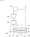
- FIG. 1 is a side view illustrating the overall configuration of an electrode drying apparatus according to the present invention
- FIG. 2 is a schematic configuration view illustrating a hot air supply unit and a temperature measuring unit according to the present invention
- FIG. 3 is a cross-sectional view taken along line I-I' in FIG. 1 .
- an electrode drying apparatus 1 may include a body 110, a transportation unit 120, a hot air supply unit 130, a temperature measuring unit 140, a moisture supply unit 150, a controller (not shown).
- the body 110 forms a main frame of the electrode drying apparatus 1, and has an internal accommodation space S provided for a drying process.
- an inlet 111 through which an electrode E to be dried is introduced may be provided on one side of the body 110, while an outlet 113 through which the electrode E that has undergone the drying process is discharged may be provided on the other side of the body 110.
- the transportation unit 120 may be configured to transport the electrode E to be dried in a single direction so that the electrode passes through the accommodation space S, serving as a drying oven, through the inlet 111 and the outlet 113.
- the transportation unit 120 may transport the electrode E to be dried in one direction using a plurality of transportation rollers 121 rotating in one direction by power received from a motor (not shown).
- This configuration of the transportation unit 120 is typically applied and used in an electrodes fabricating process, and a detailed description thereof will be omitted herein.
- the hot air supply unit 130 serves to dry the electrode E to be dried by blowing hot air toward the electrode E to be dried transported by the transportation unit 120.
- the hot air supply unit 130 may include an upper trunk 131 having a hot air supply passage provided therein and a lower trunk 132 spaced apart from the upper trunk 131 such that the electrode E to be dried is transported in one direction between the upper trunk 131 and the lower trunk 132.
- Discharge holes 131a and 132a able to supply the hot air toward the electrode E to be dried may be formed through portions of the upper trunk 131 and the lower trunk 132 that face each other.
- a heat exchanger 133 heating external air supplied thereto and a blower fan 135 supplying the external air heated by the heat exchanger 133 into the accommodation space S may be connected to each of the upper trunk 131 and the lower trunk 132.
- Reference numeral 139 which has not been described, indicates a high-efficiency particulate air (HEPA) filter removing particles in the supplied hot air.
- HEPA high-efficiency particulate air
- the hot air supplied into the accommodation space S of the body 110 is used for drying the electrode E to be dried. Afterwards, a portion of the hot air circulates, while the remaining portion of the hot air is discharged outwards.
- the hot air supply unit 130 may include dampers 137 provided within ducts 115 communicating with the interior of the accommodation space S of the body 110, such that each of the dampers 137 is operated by an actuator (not shown).
- the hot air supply unit 130 may adjust the amount of the hot air supplied into the accommodation space S using the damper 137 (see FIG. 3 ).
- the temperature measuring unit 140 serves to measure the internal temperature of the accommodation space S.
- the temperature measuring unit 140 may include a first sensor 141 measuring the temperature of the hot air supplied by the hot air supply unit 130, a second sensor 143 monitoring the internal temperature of the accommodation space S in real time, and a third sensor 145 measuring the temperature of air discharged from the accommodation space S (see FIG. 2 ).
- the third sensor 145 from among the plurality of sensors 141, 143, and 145 of the temperature measuring unit 140, may measure whether or not the internal temperature of the accommodation space S is a predetermined reference value.
- the moisture supply unit 150 serves to supply moisture into the accommodation space S before the electrode E to be dried passes through the accommodation space S.
- the moisture supply unit 150 lowers the internal temperature of the accommodation space S to the predetermined reference value and stabilizes the internal temperature using the evaporation heat of the supplied moisture.
- the moisture supply unit 150 may include moisture spray nozzles 151 disposed within the ducts 115 connected to the accommodation space S and supplying the moisture in the form of mist, so that the moisture is contained in and supplied together with the hot air supplied into the accommodation space S (see FIG. 3 ).
- a drain hole 117 may be provided in the bottom of the duct 115 such that water may be discharged outwards through the drain hole 117 when the water leaks from the moisture supply unit 150.
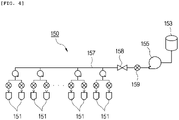
- FIG. 4 is a schematic view illustrating a structure in which a moisture supply unit is connected to the electrode drying apparatus according to the present invention.
- the moisture supply unit 150 may include a storage tank 153 in which ultrapure water (or deionized (DI) water) is stored and a supply pump 155 supplying the ultrapure water stored in the storage tank 153 to the moisture spray nozzles 151 through a supply line 157.
- DI deionized
- the electrode drying apparatus 1 having the above-described configuration may be provided as a plurality of electrode drying apparatuses spaced apart from each other in parallel, and the ultrapure water stored in the storage tank 153 may be supplied to the plurality of electrode drying apparatuses 1 through the supply line 157.
- an on-off valve 158 and a flow meter 159 may be disposed on the supply line 157 connected to the electrode drying apparatus 1.
- the on-off valve 158 and the flow meter 159 may monitor and control, in real time, a total amount of the ultrapure water supplied to the electrode drying apparatus 1.
- the controller may control the overall elements 120, 130, 140, and 150 disposed in the body 110.
- the controller measures the internal temperature of the accommodation space S before the electrode E to be dried is introduced into the accommodation space S of the electrode drying apparatus 1, and then, determines whether or not the measured internal temperature of the accommodation space S is a level at which the drying of the electrode E to be dried is stabilized.
- the moisture supply unit 150 sprays moisture into the accommodation space to cool the accommodation space.
- the level at which the drying of the electrode E to be dried is stabilized may be maintained, thereby preventing the electrode E to be dried from being peeled or cracked by over-drying of the electrode at the early stage of the drying process.
- the third sensor 145 of the temperature measuring unit 140 measures the internal temperature of the accommodation space S.
- the moisture supply unit 150 sprays the moisture into the accommodation space S so as to cool the accommodation space.
- the moisture supply unit 150 allows the moisture to be contained in and supplied together with the hot air supplied into the accommodation space S.
- the controller determines whether or not the internal temperature of the accommodation space S has reached the reference value by the evaporation heat of the moisture supplied into the accommodation space S. In this case, the controller adjusts the amount of moisture sprayed by the moisture supply unit 150 by comparing the measured temperature of air discharged through the accommodation space S with the reference value.
- the supply of the moisture into the accommodation space S is stopped, and then, the drying process is performed by allowing the electrode E to be dried to pass through the accommodation space S.
Landscapes
- Engineering & Computer Science (AREA)
- Mechanical Engineering (AREA)
- General Engineering & Computer Science (AREA)
- Chemical & Material Sciences (AREA)
- Life Sciences & Earth Sciences (AREA)
- Microbiology (AREA)
- Textile Engineering (AREA)
- Manufacturing & Machinery (AREA)
- Chemical Kinetics & Catalysis (AREA)
- Electrochemistry (AREA)
- General Chemical & Material Sciences (AREA)
- Materials Engineering (AREA)
- Drying Of Solid Materials (AREA)
- Battery Electrode And Active Subsutance (AREA)
- Processing And Handling Of Plastics And Other Materials For Molding In General (AREA)
Applications Claiming Priority (2)
| Application Number | Priority Date | Filing Date | Title |
|---|---|---|---|
| KR1020190093890A KR102752344B1 (ko) | 2019-08-01 | 2019-08-01 | 수분공급부가 구비된 전극 건조 장치 및 이를 이용한 전극 건조 방법 |
| PCT/KR2020/009337 WO2021020774A1 (ko) | 2019-08-01 | 2020-07-15 | 수분공급부가 구비된 전극 건조 장치 및 이를 이용한 전극 건조 방법 |
Publications (3)
| Publication Number | Publication Date |
|---|---|
| EP4001815A1 true EP4001815A1 (de) | 2022-05-25 |
| EP4001815A4 EP4001815A4 (de) | 2022-07-13 |
| EP4001815B1 EP4001815B1 (de) | 2024-05-15 |
Family
ID=74228648
Family Applications (1)
| Application Number | Title | Priority Date | Filing Date |
|---|---|---|---|
| EP20847966.7A Active EP4001815B1 (de) | 2019-08-01 | 2020-07-15 | Elektrodentrocknungsvorrichtung mit einem wasserzufuhrteil und verfahren zum trocknen einer elektrode damit |
Country Status (7)
| Country | Link |
|---|---|
| US (1) | US12435925B2 (de) |
| EP (1) | EP4001815B1 (de) |
| KR (1) | KR102752344B1 (de) |
| CN (1) | CN114174748B (de) |
| ES (1) | ES2980365T3 (de) |
| HU (1) | HUE066876T2 (de) |
| WO (1) | WO2021020774A1 (de) |
Cited By (1)
| Publication number | Priority date | Publication date | Assignee | Title |
|---|---|---|---|---|
| JP2025532491A (ja) * | 2023-03-09 | 2025-10-01 | エルジー エナジー ソリューション リミテッド | 電極シートの乾燥装置及び乾燥方法 |
Families Citing this family (8)
| Publication number | Priority date | Publication date | Assignee | Title |
|---|---|---|---|---|
| ES3032338T3 (en) * | 2021-03-08 | 2025-07-17 | Lg Energy Solution Ltd | Electrode drying device |
| KR102917916B1 (ko) * | 2021-09-08 | 2026-01-23 | 주식회사 엘지에너지솔루션 | 전극 건조 시스템 |
| US20240072236A1 (en) * | 2021-11-18 | 2024-02-29 | Lg Energy Solution, Ltd. | Electrode Manufacturing Apparatus and Method |
| KR20230146843A (ko) | 2022-04-13 | 2023-10-20 | 주식회사 엘지에너지솔루션 | 전극의 건조 시스템 및 전극의 제조 시스템 |
| EP4280294A1 (de) * | 2022-05-19 | 2023-11-22 | LG Energy Solution, Ltd. | Verfahren und system zum trocknen eines batterieteils |
| KR20240054704A (ko) | 2022-10-19 | 2024-04-26 | 주식회사 엘지에너지솔루션 | 전극 건조장치 및 전극 건조방법 |
| KR20240143062A (ko) | 2023-03-23 | 2024-10-02 | 주식회사 엘지에너지솔루션 | 전극 시트의 건조장치 및 건조방법 |
| KR20240175022A (ko) * | 2023-06-12 | 2024-12-19 | 주식회사 엘지에너지솔루션 | 전극 시트 건조용 유체 분사 장치 및 이를 포함하는 전극 시트 건조 장치 |
Family Cites Families (26)
| Publication number | Priority date | Publication date | Assignee | Title |
|---|---|---|---|---|
| US6783601B2 (en) * | 2002-06-06 | 2004-08-31 | Donald Gray | Method for removing particles and non-volatile residue from an object |
| JP2008103098A (ja) * | 2006-10-17 | 2008-05-01 | Matsushita Electric Ind Co Ltd | 非水電解液二次電池用電極板の製造方法およびその製造装置 |
| CA2629495A1 (en) * | 2008-04-18 | 2009-10-18 | Mabe Canada Inc. | Apparatus for controlling a clothes dryer |
| JP5277818B2 (ja) * | 2008-09-12 | 2013-08-28 | 日産自動車株式会社 | 電極材乾燥装置、および電極材乾燥方法 |
| JP5534771B2 (ja) * | 2009-10-09 | 2014-07-02 | パナソニック株式会社 | 塗布膜の乾燥方法と乾燥装置 |
| US8613681B2 (en) | 2009-11-19 | 2013-12-24 | GM Global Technology Operations LLC | Transmission hydraulic control system having clutch compensator feed override |
| KR101191627B1 (ko) | 2010-11-26 | 2012-10-17 | 삼성에스디아이 주식회사 | 이차전지의 전극판 건조장치 및 그 제어방법 |
| CN102072620B (zh) * | 2011-01-28 | 2012-12-05 | 福建南平南孚电池有限公司 | 一种用于电池极片的真空烘箱 |
| CN102110803B (zh) * | 2011-01-28 | 2012-09-26 | 福建南平南孚电池有限公司 | 锂铁电池的正极电极材料的烘干方法 |
| US9834882B2 (en) * | 2011-07-07 | 2017-12-05 | Haier Us Appliance Solutions, Inc. | Device and method for heat pump based clothes dryer |
| JP5392332B2 (ja) * | 2011-09-15 | 2014-01-22 | 第一実業株式会社 | 乾燥装置 |
| EP2570772A1 (de) | 2011-09-16 | 2013-03-20 | Deutsches Zentrum für Luft- und Raumfahrt e.V. | Verfahren zur Lokalisation und Kartierung von Fußgängern und Robotern unter Verwendung von drahtlosen Zugangspunkten |
| JP5909986B2 (ja) * | 2011-10-19 | 2016-04-27 | 日産自動車株式会社 | 電極乾燥方法、および電極乾燥装置 |
| JP5655769B2 (ja) * | 2011-12-09 | 2015-01-21 | トヨタ自動車株式会社 | 電極の製造方法 |
| JP2014001914A (ja) * | 2012-06-20 | 2014-01-09 | Toyota Motor Corp | 電極シート乾燥システム |
| JP5259875B1 (ja) * | 2012-07-19 | 2013-08-07 | 日本碍子株式会社 | 電池用電極塗膜の乾燥方法及び乾燥炉 |
| US10276857B2 (en) | 2012-09-25 | 2019-04-30 | Toyota Jidosha Kabushiki Kaisha | Method of manufacturing electrode for secondary battery and hot-gas drying furnace |
| KR102110534B1 (ko) * | 2013-12-12 | 2020-05-13 | 엘지전자 주식회사 | 의류처리기기의 제어방법 |
| KR102257677B1 (ko) | 2014-05-15 | 2021-05-28 | 삼성에스디아이 주식회사 | 전극판 건조 장치 및 전극판 건조 방법 |
| JP2016058335A (ja) * | 2014-09-12 | 2016-04-21 | 株式会社日立製作所 | 全固体電池およびその製造方法、容量回復方法 |
| KR101735034B1 (ko) | 2014-09-29 | 2017-05-12 | 주식회사 엘지화학 | 전극 건조장치 |
| KR20170109912A (ko) * | 2016-03-22 | 2017-10-10 | 삼성에스디아이 주식회사 | 극판 건조 장치 |
| KR102277230B1 (ko) * | 2017-01-03 | 2021-07-14 | 주식회사 엘지에너지솔루션 | 언와인더 및 리와인더를 포함하는 전극 건조 장치 |
| KR102516223B1 (ko) * | 2017-08-17 | 2023-03-30 | 주식회사 엘지에너지솔루션 | 전극 가열장치 및 그를 포함하는 이차전지용 제조시스템 |
| CN109971894A (zh) * | 2017-12-28 | 2019-07-05 | 广州春英电器有限责任公司 | 微电脑智能控制空气加湿系统 |
| CN109365245B (zh) * | 2018-10-24 | 2021-08-10 | 佛山市金银河智能装备股份有限公司 | 一种电池极片气浮式烘箱 |
-
2019
- 2019-08-01 KR KR1020190093890A patent/KR102752344B1/ko active Active
-
2020
- 2020-07-15 CN CN202080054757.2A patent/CN114174748B/zh active Active
- 2020-07-15 US US17/631,663 patent/US12435925B2/en active Active
- 2020-07-15 WO PCT/KR2020/009337 patent/WO2021020774A1/ko not_active Ceased
- 2020-07-15 EP EP20847966.7A patent/EP4001815B1/de active Active
- 2020-07-15 HU HUE20847966A patent/HUE066876T2/hu unknown
- 2020-07-15 ES ES20847966T patent/ES2980365T3/es active Active
Cited By (2)
| Publication number | Priority date | Publication date | Assignee | Title |
|---|---|---|---|---|
| JP2025532491A (ja) * | 2023-03-09 | 2025-10-01 | エルジー エナジー ソリューション リミテッド | 電極シートの乾燥装置及び乾燥方法 |
| EP4567915A4 (de) * | 2023-03-09 | 2026-02-25 | Lg Energy Solution Ltd | Trocknungsvorrichtung und trocknungsverfahren für elektrodenfolie |
Also Published As
| Publication number | Publication date |
|---|---|
| KR102752344B1 (ko) | 2025-01-10 |
| WO2021020774A1 (ko) | 2021-02-04 |
| US12435925B2 (en) | 2025-10-07 |
| US20220276001A1 (en) | 2022-09-01 |
| EP4001815A4 (de) | 2022-07-13 |
| KR20210015278A (ko) | 2021-02-10 |
| CN114174748A (zh) | 2022-03-11 |
| HUE066876T2 (hu) | 2024-09-28 |
| EP4001815B1 (de) | 2024-05-15 |
| ES2980365T3 (es) | 2024-10-01 |
| CN114174748B (zh) | 2023-03-24 |
Similar Documents
| Publication | Publication Date | Title |
|---|---|---|
| EP4001815B1 (de) | Elektrodentrocknungsvorrichtung mit einem wasserzufuhrteil und verfahren zum trocknen einer elektrode damit | |
| KR101422429B1 (ko) | 건조 장치 및 열처리 시스템 | |
| KR101467640B1 (ko) | 전극 건조 방법 및 전극 건조 장치 | |
| KR101550487B1 (ko) | 전극 건조 방법 및 전극 건조 장치 | |
| KR101286003B1 (ko) | 이차 전지의 전극 슬러리 건조 방법 및 장치 | |
| JP2013137139A (ja) | 乾燥装置および熱処理システム | |
| JP7782912B2 (ja) | 電極シートの乾燥装置、それを含む電極シートの製造システム、および電極シートの乾燥方法 | |
| CN214065481U (zh) | 一种硅片烘干装置 | |
| CN110360815A (zh) | 一种温湿度控制的热风与真空脉动组合干燥方法与设备 | |
| CN120479720A (zh) | 涂布设备 | |
| JP7522311B2 (ja) | 電極乾燥システム | |
| WO2023246220A1 (zh) | 极片烘干装置、电池生产设备及极片烘干方法 | |
| KR20150131561A (ko) | 전극판 건조 장치 및 전극판 건조 방법 | |
| CN207834442U (zh) | 涂布烘干设备 | |
| KR102926755B1 (ko) | 배터리 부품 건조 방법 및 시스템 | |
| JP2015083920A (ja) | 乾燥装置および熱処理システム | |
| US20260118059A1 (en) | Oven drying apparatus and electrode plate manufacturing device | |
| EP4328533B1 (de) | Elektrodenblatt-ofentrocknungsvorrichtung, batterieherstellungsvorrichtung und elektrodenblatt-ofentrocknungsverfahren | |
| CN204809312U (zh) | 一种电池极板高温固化室 | |
| CN209101733U (zh) | 一种连续式碳素纤维远红外干燥机 | |
| CN219664310U (zh) | 一种极片烘箱及电池生产设备 | |
| CN118073628A (zh) | 一种电芯热整形烘箱及烘烤方法 | |
| KR20230073131A (ko) | 전극 제조 장치 및 방법 | |
| CN116989567A (zh) | 一种木材真空干燥设备及工艺 | |
| CN121297403A (zh) | 锂离子电池极片干燥装置、方法和锂离子电池极片 |
Legal Events
| Date | Code | Title | Description |
|---|---|---|---|
| STAA | Information on the status of an ep patent application or granted ep patent |
Free format text: STATUS: THE INTERNATIONAL PUBLICATION HAS BEEN MADE |
|
| PUAI | Public reference made under article 153(3) epc to a published international application that has entered the european phase |
Free format text: ORIGINAL CODE: 0009012 |
|
| STAA | Information on the status of an ep patent application or granted ep patent |
Free format text: STATUS: REQUEST FOR EXAMINATION WAS MADE |
|
| 17P | Request for examination filed |
Effective date: 20220218 |
|
| AK | Designated contracting states |
Kind code of ref document: A1 Designated state(s): AL AT BE BG CH CY CZ DE DK EE ES FI FR GB GR HR HU IE IS IT LI LT LU LV MC MK MT NL NO PL PT RO RS SE SI SK SM TR |
|
| A4 | Supplementary search report drawn up and despatched |
Effective date: 20220610 |
|
| RIC1 | Information provided on ipc code assigned before grant |
Ipc: H01M 4/00 20060101ALI20220603BHEP Ipc: F26B 21/10 20060101ALI20220603BHEP Ipc: F26B 13/12 20060101ALI20220603BHEP Ipc: F26B 13/20 20060101ALI20220603BHEP Ipc: F26B 3/04 20060101ALI20220603BHEP Ipc: F26B 21/08 20060101ALI20220603BHEP Ipc: F26B 21/00 20060101ALI20220603BHEP Ipc: F26B 15/12 20060101ALI20220603BHEP Ipc: F26B 3/12 20060101AFI20220603BHEP |
|
| DAV | Request for validation of the european patent (deleted) | ||
| DAX | Request for extension of the european patent (deleted) | ||
| GRAP | Despatch of communication of intention to grant a patent |
Free format text: ORIGINAL CODE: EPIDOSNIGR1 |
|
| STAA | Information on the status of an ep patent application or granted ep patent |
Free format text: STATUS: GRANT OF PATENT IS INTENDED |
|
| RIC1 | Information provided on ipc code assigned before grant |
Ipc: H01M 4/00 20060101ALI20240207BHEP Ipc: F26B 21/10 20060101ALI20240207BHEP Ipc: F26B 13/12 20060101ALI20240207BHEP Ipc: F26B 13/20 20060101ALI20240207BHEP Ipc: F26B 3/04 20060101ALI20240207BHEP Ipc: F26B 21/08 20060101ALI20240207BHEP Ipc: F26B 21/00 20060101ALI20240207BHEP Ipc: F26B 15/12 20060101ALI20240207BHEP Ipc: F26B 3/12 20060101AFI20240207BHEP |
|
| INTG | Intention to grant announced |
Effective date: 20240227 |
|
| GRAS | Grant fee paid |
Free format text: ORIGINAL CODE: EPIDOSNIGR3 |
|
| P01 | Opt-out of the competence of the unified patent court (upc) registered |
Effective date: 20240301 |
|
| GRAA | (expected) grant |
Free format text: ORIGINAL CODE: 0009210 |
|
| STAA | Information on the status of an ep patent application or granted ep patent |
Free format text: STATUS: THE PATENT HAS BEEN GRANTED |
|
| AK | Designated contracting states |
Kind code of ref document: B1 Designated state(s): AL AT BE BG CH CY CZ DE DK EE ES FI FR GB GR HR HU IE IS IT LI LT LU LV MC MK MT NL NO PL PT RO RS SE SI SK SM TR |
|
| REG | Reference to a national code |
Ref country code: CH Ref legal event code: EP |
|
| REG | Reference to a national code |
Ref country code: DE Ref legal event code: R096 Ref document number: 602020031078 Country of ref document: DE |
|
| REG | Reference to a national code |
Ref country code: IE Ref legal event code: FG4D |
|
| REG | Reference to a national code |
Ref country code: LT Ref legal event code: MG9D |
|
| REG | Reference to a national code |
Ref country code: NL Ref legal event code: MP Effective date: 20240515 |
|
| REG | Reference to a national code |
Ref country code: HU Ref legal event code: AG4A Ref document number: E066876 Country of ref document: HU |
|
| REG | Reference to a national code |
Ref country code: ES Ref legal event code: FG2A Ref document number: 2980365 Country of ref document: ES Kind code of ref document: T3 Effective date: 20241001 |
|
| PG25 | Lapsed in a contracting state [announced via postgrant information from national office to epo] |
Ref country code: IS Free format text: LAPSE BECAUSE OF FAILURE TO SUBMIT A TRANSLATION OF THE DESCRIPTION OR TO PAY THE FEE WITHIN THE PRESCRIBED TIME-LIMIT Effective date: 20240915 |
|
| PG25 | Lapsed in a contracting state [announced via postgrant information from national office to epo] |
Ref country code: BG Free format text: LAPSE BECAUSE OF FAILURE TO SUBMIT A TRANSLATION OF THE DESCRIPTION OR TO PAY THE FEE WITHIN THE PRESCRIBED TIME-LIMIT Effective date: 20240515 |
|
| PG25 | Lapsed in a contracting state [announced via postgrant information from national office to epo] |
Ref country code: FI Free format text: LAPSE BECAUSE OF FAILURE TO SUBMIT A TRANSLATION OF THE DESCRIPTION OR TO PAY THE FEE WITHIN THE PRESCRIBED TIME-LIMIT Effective date: 20240515 Ref country code: HR Free format text: LAPSE BECAUSE OF FAILURE TO SUBMIT A TRANSLATION OF THE DESCRIPTION OR TO PAY THE FEE WITHIN THE PRESCRIBED TIME-LIMIT Effective date: 20240515 |
|
| PG25 | Lapsed in a contracting state [announced via postgrant information from national office to epo] |
Ref country code: GR Free format text: LAPSE BECAUSE OF FAILURE TO SUBMIT A TRANSLATION OF THE DESCRIPTION OR TO PAY THE FEE WITHIN THE PRESCRIBED TIME-LIMIT Effective date: 20240816 |
|
| PG25 | Lapsed in a contracting state [announced via postgrant information from national office to epo] |
Ref country code: PT Free format text: LAPSE BECAUSE OF FAILURE TO SUBMIT A TRANSLATION OF THE DESCRIPTION OR TO PAY THE FEE WITHIN THE PRESCRIBED TIME-LIMIT Effective date: 20240916 |
|
| REG | Reference to a national code |
Ref country code: AT Ref legal event code: MK05 Ref document number: 1687227 Country of ref document: AT Kind code of ref document: T Effective date: 20240515 |
|
| PG25 | Lapsed in a contracting state [announced via postgrant information from national office to epo] |
Ref country code: NL Free format text: LAPSE BECAUSE OF FAILURE TO SUBMIT A TRANSLATION OF THE DESCRIPTION OR TO PAY THE FEE WITHIN THE PRESCRIBED TIME-LIMIT Effective date: 20240515 |
|
| PG25 | Lapsed in a contracting state [announced via postgrant information from national office to epo] |
Ref country code: AT Free format text: LAPSE BECAUSE OF FAILURE TO SUBMIT A TRANSLATION OF THE DESCRIPTION OR TO PAY THE FEE WITHIN THE PRESCRIBED TIME-LIMIT Effective date: 20240515 |
|
| PG25 | Lapsed in a contracting state [announced via postgrant information from national office to epo] |
Ref country code: PL Free format text: LAPSE BECAUSE OF FAILURE TO SUBMIT A TRANSLATION OF THE DESCRIPTION OR TO PAY THE FEE WITHIN THE PRESCRIBED TIME-LIMIT Effective date: 20240515 |
|
| PG25 | Lapsed in a contracting state [announced via postgrant information from national office to epo] |
Ref country code: LV Free format text: LAPSE BECAUSE OF FAILURE TO SUBMIT A TRANSLATION OF THE DESCRIPTION OR TO PAY THE FEE WITHIN THE PRESCRIBED TIME-LIMIT Effective date: 20240515 |
|
| PG25 | Lapsed in a contracting state [announced via postgrant information from national office to epo] |
Ref country code: PT Free format text: LAPSE BECAUSE OF FAILURE TO SUBMIT A TRANSLATION OF THE DESCRIPTION OR TO PAY THE FEE WITHIN THE PRESCRIBED TIME-LIMIT Effective date: 20240916 Ref country code: PL Free format text: LAPSE BECAUSE OF FAILURE TO SUBMIT A TRANSLATION OF THE DESCRIPTION OR TO PAY THE FEE WITHIN THE PRESCRIBED TIME-LIMIT Effective date: 20240515 Ref country code: NO Free format text: LAPSE BECAUSE OF FAILURE TO SUBMIT A TRANSLATION OF THE DESCRIPTION OR TO PAY THE FEE WITHIN THE PRESCRIBED TIME-LIMIT Effective date: 20240815 Ref country code: NL Free format text: LAPSE BECAUSE OF FAILURE TO SUBMIT A TRANSLATION OF THE DESCRIPTION OR TO PAY THE FEE WITHIN THE PRESCRIBED TIME-LIMIT Effective date: 20240515 Ref country code: LV Free format text: LAPSE BECAUSE OF FAILURE TO SUBMIT A TRANSLATION OF THE DESCRIPTION OR TO PAY THE FEE WITHIN THE PRESCRIBED TIME-LIMIT Effective date: 20240515 Ref country code: IS Free format text: LAPSE BECAUSE OF FAILURE TO SUBMIT A TRANSLATION OF THE DESCRIPTION OR TO PAY THE FEE WITHIN THE PRESCRIBED TIME-LIMIT Effective date: 20240915 Ref country code: HR Free format text: LAPSE BECAUSE OF FAILURE TO SUBMIT A TRANSLATION OF THE DESCRIPTION OR TO PAY THE FEE WITHIN THE PRESCRIBED TIME-LIMIT Effective date: 20240515 Ref country code: GR Free format text: LAPSE BECAUSE OF FAILURE TO SUBMIT A TRANSLATION OF THE DESCRIPTION OR TO PAY THE FEE WITHIN THE PRESCRIBED TIME-LIMIT Effective date: 20240816 Ref country code: FI Free format text: LAPSE BECAUSE OF FAILURE TO SUBMIT A TRANSLATION OF THE DESCRIPTION OR TO PAY THE FEE WITHIN THE PRESCRIBED TIME-LIMIT Effective date: 20240515 Ref country code: BG Free format text: LAPSE BECAUSE OF FAILURE TO SUBMIT A TRANSLATION OF THE DESCRIPTION OR TO PAY THE FEE WITHIN THE PRESCRIBED TIME-LIMIT Effective date: 20240515 Ref country code: AT Free format text: LAPSE BECAUSE OF FAILURE TO SUBMIT A TRANSLATION OF THE DESCRIPTION OR TO PAY THE FEE WITHIN THE PRESCRIBED TIME-LIMIT Effective date: 20240515 Ref country code: RS Free format text: LAPSE BECAUSE OF FAILURE TO SUBMIT A TRANSLATION OF THE DESCRIPTION OR TO PAY THE FEE WITHIN THE PRESCRIBED TIME-LIMIT Effective date: 20240815 |
|
| PG25 | Lapsed in a contracting state [announced via postgrant information from national office to epo] |
Ref country code: DK Free format text: LAPSE BECAUSE OF FAILURE TO SUBMIT A TRANSLATION OF THE DESCRIPTION OR TO PAY THE FEE WITHIN THE PRESCRIBED TIME-LIMIT Effective date: 20240515 |
|
| PG25 | Lapsed in a contracting state [announced via postgrant information from national office to epo] |
Ref country code: EE Free format text: LAPSE BECAUSE OF FAILURE TO SUBMIT A TRANSLATION OF THE DESCRIPTION OR TO PAY THE FEE WITHIN THE PRESCRIBED TIME-LIMIT Effective date: 20240515 |
|
| PG25 | Lapsed in a contracting state [announced via postgrant information from national office to epo] |
Ref country code: CZ Free format text: LAPSE BECAUSE OF FAILURE TO SUBMIT A TRANSLATION OF THE DESCRIPTION OR TO PAY THE FEE WITHIN THE PRESCRIBED TIME-LIMIT Effective date: 20240515 |
|
| PG25 | Lapsed in a contracting state [announced via postgrant information from national office to epo] |
Ref country code: SK Free format text: LAPSE BECAUSE OF FAILURE TO SUBMIT A TRANSLATION OF THE DESCRIPTION OR TO PAY THE FEE WITHIN THE PRESCRIBED TIME-LIMIT Effective date: 20240515 Ref country code: RO Free format text: LAPSE BECAUSE OF FAILURE TO SUBMIT A TRANSLATION OF THE DESCRIPTION OR TO PAY THE FEE WITHIN THE PRESCRIBED TIME-LIMIT Effective date: 20240515 |
|
| PG25 | Lapsed in a contracting state [announced via postgrant information from national office to epo] |
Ref country code: SM Free format text: LAPSE BECAUSE OF FAILURE TO SUBMIT A TRANSLATION OF THE DESCRIPTION OR TO PAY THE FEE WITHIN THE PRESCRIBED TIME-LIMIT Effective date: 20240515 |
|
| PG25 | Lapsed in a contracting state [announced via postgrant information from national office to epo] |
Ref country code: SM Free format text: LAPSE BECAUSE OF FAILURE TO SUBMIT A TRANSLATION OF THE DESCRIPTION OR TO PAY THE FEE WITHIN THE PRESCRIBED TIME-LIMIT Effective date: 20240515 Ref country code: SK Free format text: LAPSE BECAUSE OF FAILURE TO SUBMIT A TRANSLATION OF THE DESCRIPTION OR TO PAY THE FEE WITHIN THE PRESCRIBED TIME-LIMIT Effective date: 20240515 Ref country code: RO Free format text: LAPSE BECAUSE OF FAILURE TO SUBMIT A TRANSLATION OF THE DESCRIPTION OR TO PAY THE FEE WITHIN THE PRESCRIBED TIME-LIMIT Effective date: 20240515 Ref country code: EE Free format text: LAPSE BECAUSE OF FAILURE TO SUBMIT A TRANSLATION OF THE DESCRIPTION OR TO PAY THE FEE WITHIN THE PRESCRIBED TIME-LIMIT Effective date: 20240515 Ref country code: DK Free format text: LAPSE BECAUSE OF FAILURE TO SUBMIT A TRANSLATION OF THE DESCRIPTION OR TO PAY THE FEE WITHIN THE PRESCRIBED TIME-LIMIT Effective date: 20240515 Ref country code: CZ Free format text: LAPSE BECAUSE OF FAILURE TO SUBMIT A TRANSLATION OF THE DESCRIPTION OR TO PAY THE FEE WITHIN THE PRESCRIBED TIME-LIMIT Effective date: 20240515 |
|
| PG25 | Lapsed in a contracting state [announced via postgrant information from national office to epo] |
Ref country code: IT Free format text: LAPSE BECAUSE OF FAILURE TO SUBMIT A TRANSLATION OF THE DESCRIPTION OR TO PAY THE FEE WITHIN THE PRESCRIBED TIME-LIMIT Effective date: 20240515 Ref country code: MC Free format text: LAPSE BECAUSE OF FAILURE TO SUBMIT A TRANSLATION OF THE DESCRIPTION OR TO PAY THE FEE WITHIN THE PRESCRIBED TIME-LIMIT Effective date: 20240515 |
|
| REG | Reference to a national code |
Ref country code: DE Ref legal event code: R097 Ref document number: 602020031078 Country of ref document: DE |
|
| REG | Reference to a national code |
Ref country code: CH Ref legal event code: PL |
|
| PG25 | Lapsed in a contracting state [announced via postgrant information from national office to epo] |
Ref country code: LU Free format text: LAPSE BECAUSE OF NON-PAYMENT OF DUE FEES Effective date: 20240715 |
|
| PLBE | No opposition filed within time limit |
Free format text: ORIGINAL CODE: 0009261 |
|
| STAA | Information on the status of an ep patent application or granted ep patent |
Free format text: STATUS: NO OPPOSITION FILED WITHIN TIME LIMIT |
|
| PG25 | Lapsed in a contracting state [announced via postgrant information from national office to epo] |
Ref country code: LU Free format text: LAPSE BECAUSE OF NON-PAYMENT OF DUE FEES Effective date: 20240715 |
|
| 26N | No opposition filed |
Effective date: 20250218 |
|
| PG25 | Lapsed in a contracting state [announced via postgrant information from national office to epo] |
Ref country code: SI Free format text: LAPSE BECAUSE OF FAILURE TO SUBMIT A TRANSLATION OF THE DESCRIPTION OR TO PAY THE FEE WITHIN THE PRESCRIBED TIME-LIMIT Effective date: 20240515 Ref country code: CH Free format text: LAPSE BECAUSE OF NON-PAYMENT OF DUE FEES Effective date: 20240731 Ref country code: BE Free format text: LAPSE BECAUSE OF NON-PAYMENT OF DUE FEES Effective date: 20240731 |
|
| REG | Reference to a national code |
Ref country code: BE Ref legal event code: MM Effective date: 20240731 |
|
| PGFP | Annual fee paid to national office [announced via postgrant information from national office to epo] |
Ref country code: GB Payment date: 20250624 Year of fee payment: 6 |
|
| PGFP | Annual fee paid to national office [announced via postgrant information from national office to epo] |
Ref country code: FR Payment date: 20250624 Year of fee payment: 6 |
|
| PG25 | Lapsed in a contracting state [announced via postgrant information from national office to epo] |
Ref country code: IE Free format text: LAPSE BECAUSE OF NON-PAYMENT OF DUE FEES Effective date: 20240715 |
|
| PGFP | Annual fee paid to national office [announced via postgrant information from national office to epo] |
Ref country code: HU Payment date: 20250721 Year of fee payment: 6 |
|
| PG25 | Lapsed in a contracting state [announced via postgrant information from national office to epo] |
Ref country code: SE Free format text: LAPSE BECAUSE OF FAILURE TO SUBMIT A TRANSLATION OF THE DESCRIPTION OR TO PAY THE FEE WITHIN THE PRESCRIBED TIME-LIMIT Effective date: 20240515 |
|
| PGFP | Annual fee paid to national office [announced via postgrant information from national office to epo] |
Ref country code: ES Payment date: 20250822 Year of fee payment: 6 |
|
| PGFP | Annual fee paid to national office [announced via postgrant information from national office to epo] |
Ref country code: DE Payment date: 20250624 Year of fee payment: 6 |
|
| PG25 | Lapsed in a contracting state [announced via postgrant information from national office to epo] |
Ref country code: CY Free format text: LAPSE BECAUSE OF FAILURE TO SUBMIT A TRANSLATION OF THE DESCRIPTION OR TO PAY THE FEE WITHIN THE PRESCRIBED TIME-LIMIT; INVALID AB INITIO Effective date: 20200715 |