EP4001833B1 - System zur schätzung der reifenprofiltiefe - Google Patents
System zur schätzung der reifenprofiltiefe Download PDFInfo
- Publication number
- EP4001833B1 EP4001833B1 EP21207482.7A EP21207482A EP4001833B1 EP 4001833 B1 EP4001833 B1 EP 4001833B1 EP 21207482 A EP21207482 A EP 21207482A EP 4001833 B1 EP4001833 B1 EP 4001833B1
- Authority
- EP
- European Patent Office
- Prior art keywords
- pulse
- time
- tread
- tire
- flight sensor
- Prior art date
- Legal status (The legal status is an assumption and is not a legal conclusion. Google has not performed a legal analysis and makes no representation as to the accuracy of the status listed.)
- Active
Links
Images




Classifications
-
- G—PHYSICS
- G01—MEASURING; TESTING
- G01B—MEASURING LENGTH, THICKNESS OR SIMILAR LINEAR DIMENSIONS; MEASURING ANGLES; MEASURING AREAS; MEASURING IRREGULARITIES OF SURFACES OR CONTOURS
- G01B11/00—Measuring arrangements characterised by the use of optical techniques
- G01B11/22—Measuring arrangements characterised by the use of optical techniques for measuring depth
-
- G—PHYSICS
- G01—MEASURING; TESTING
- G01M—TESTING STATIC OR DYNAMIC BALANCE OF MACHINES OR STRUCTURES; TESTING OF STRUCTURES OR APPARATUS, NOT OTHERWISE PROVIDED FOR
- G01M17/00—Testing of vehicles
- G01M17/007—Wheeled or endless-tracked vehicles
- G01M17/02—Tyres
- G01M17/027—Tyres using light, e.g. infrared, ultraviolet or holographic techniques
-
- B—PERFORMING OPERATIONS; TRANSPORTING
- B60—VEHICLES IN GENERAL
- B60C—VEHICLE TYRES; TYRE INFLATION; TYRE CHANGING; CONNECTING VALVES TO INFLATABLE ELASTIC BODIES IN GENERAL; DEVICES OR ARRANGEMENTS RELATED TO TYRES
- B60C11/00—Tyre tread bands; Tread patterns; Anti-skid inserts
- B60C11/24—Wear-indicating arrangements
- B60C11/246—Tread wear monitoring systems
Definitions
- the invention relates generally to tire monitoring. More particularly, the invention relates to systems and methods that sense a tread depth of a vehicle tire. Specifically, the invention is directed to a non-contact sensor for determining tread depth using time-of-flight.
- tread wear which refers to the loss of material from the tread of the tire, directly affects such vehicle factors.
- tread wear indicators In order to inform a vehicle user of the tire wear state, tread wear indicators have been developed. Some tread wear indicators involve providing features formed in the tire tread. When the tread wears down to the same level as the indicators, the tire should be replaced. However, it may be difficult for a user to see such an indicator and/or accurately determine the tire wear state from such an indicator.
- Still other indicators have been developed that involve electronic sensors which are mounted in the tire tread to measure tire wear and provide an alert or signal to the user as to the wear state of the tire. While such sensors are suitable for their intended purpose, they add to the complexity and cost of the tire and may not function properly under all circumstances.
- WO96/10727 A1 discloses an apparatus and a method for determining physical characteristics of a tyre mounted on a wheel fitted to a vehicle, which apparatus comprises scanning means adapted to scan a tyre and to produce an output indicative of information relating to tread depth, and indicator means responsive to the output of the scanning means to provide an indication of tread depth.
- US2017/246916 A1 discloses a tyre condition monitoring system comprising a sensing unit adapted for approximation to a tyre to take a measurement of, or at least from which can be derived, tread depth, the sensing unit being adapted for deployment by manual approximation to a tyre and to store and/or transmit measurement data from one or more or all of a set of tyres on a vehicle as well as for mechanical approximation to a tyre for continuing and/or programmed measurement.
- the invention relates to a system in accordance with claim 1 and to a method in accordance with claim 13.
- a system for estimating a tread depth of a tire supporting a vehicle.
- the tire includes a pair of sidewalls extending to a circumferential tread.
- the system includes a sensor unit, which includes a non-contact time-of-flight sensor.
- the time-of-flight sensor includes an emitter that emits a first pulse to an outer surface of the tread, and a lens that captures the first pulse after it reflects off of the outer surface of the tread.
- a processor measures a time from emission of the first pulse to capture of the reflected first pulse and calculates a tread surface distance from the time from emission of the first pulse to capture of the reflected first pulse.
- the emitter emits a second pulse to a base of a groove formed in the tread, and the lens captures the second pulse after it reflects off of the base of the groove.
- the processor measures a time from emission of the second pulse to capture of the second pulse and calculates a reference distance from the time from emission of the second pulse to capture of the second pulse.
- the processor determines a depth of the tread from a difference between the tread surface distance and the reference distance.
- a method for estimating a tread depth of a tire supporting a vehicle includes providing a tire that includes a pair of sidewalls extending to a circumferential tread.
- a sensor unit is provided that includes a non-contact time-of-flight sensor, and the sensor emits a first pulse to an outer surface of the tread and captures the first pulse after it reflects off of the outer surface of the tread.
- a time from the emission of the first pulse to the capture of the reflected first pulse is measured, and a tread surface distance is calculated from the time from the emission of the first pulse to the capture of the reflected first pulse.
- a second pulse is emitted to a base of a groove formed in the tread with the time-of-flight sensor, and the second pulse is captured with the time-of-flight sensor after the second pulse reflects off of the base of the groove.
- a time from the emission of the second pulse to the capture of the second pulse is measured, and a reference distance from the time from the emission of the second pulse to the capture of the second pulse is calculated.
- a depth of the tread is determined from a difference between the tread surface distance and the reference distance.
- the processor is an internal processor in the time-of-flight sensor.
- the processor is a processor that is remote from the time-of-flight sensor.
- Axial and “axially” means lines or directions that are parallel to the axis of rotation of the tire.
- “Circumferential” means lines or directions extending along the perimeter of the surface of the annular tread perpendicular to the axial direction.
- Equatorial centerplane means the plane perpendicular to the tire's axis of rotation and passing through the center of the tread.
- “Lateral” means an axial direction.
- Ring and radially means directions radially toward or away from the axis of rotation of the tire.
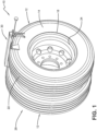
- the system 10 estimates the tread depth of each tire 12 supporting a vehicle, thereby indicating the tire wear state. It is to be understood that the vehicle may be any vehicle type.
- the tire 12 includes a pair of sidewalls including a first sidewall 14 and a second sidewall 16 extending from respective bead areas 18 and 20 to a circumferential tread 22, which wears with age from road abrasion.
- the tire 12 is preferably mounted on a rim or wheel 24 in a conventional manner as known to those skilled in the art.
- the system 10 includes a sensor unit 30 that measures the depth of the tread 22 of the tire 12 in any type of configuration.
- the sensor unit 30 may measure the depth of one tire 12 in a dual tire configuration 26 as shown in Figure 1 , both tires in the dual tire configuration as shown in Figure 2 , or the tire in a single tire configuration 28 as shown in Figure 3 , including a super-single or wide tire configuration.
- the sensor unit 30 includes a non-contact time-of-flight sensor 32 that determines the depth of the tread 22 using time-of-flight principles.
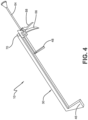
- the time-of-flight sensor 32 is mounted on a preferably handheld rail system 34, which provides stable and repeatable positioning of the time-of-flight sensor.
- the time-of-flight sensor 32 includes an emitter 36, such as a light emitting diode (LED) or a laser diode.
- the emitter 36 emits a pulse 38, which preferably is a pulse of infrared (IR) light.
- the emitted pulse 38 travels to the tread 22 and is reflected off of an outer surface 40 of the tread as a reflected pulse 42.
- the reflected pulse 42 returns to a lens 44 of the time-of-flight sensor 32, which collects the reflected pulse.
- the time-of-flight sensor 32 includes an internal processor 76 that measures the time from emission of the emitted pulse 38 to capture of the reflected pulse 42, which is the time-of-flight.
- a reference distance 54 is provided between a base 50 of a predetermined groove 52 formed in the tread 22 and the time-of-flight sensor 32.
- the processor 76 of the time-of-flight sensor 32 calculates the reference distance 54 by measuring the time-of-flight of the pulse 38 and 42 between the time-of-flight sensor and the groove base 50.
- the processor 76 of the time-of-flight sensor 32 also calculates a distance 56 from the sensor to the tread surface 40 using the time-of-flight of the pulse 38 and 42 at the tread surface. Because the base 50 of the groove 52 is the last portion of the tread 22 to wear, it is a constant value, enabling the processor 76 to determine the current depth of the tread 22 from the difference between the reference distance 54 and the tread surface distance 56. The current depth of the tread 22 may then be compared to a limit value to generate a wear state of the tread.
- the rail system 34 includes a distal mounting plate 46, which engages the tire 12 near the second sidewall 16, and a proximal mounting plate 48, which engages the tire near the first sidewall 14.
- the proximal mounting plate 48 is axially adjustable using a guide rod 64 and handle 66 with a releasable locking lever 68.
- the adjustable proximal mounting plate 48 ensures secure engagement of the distal mounting plate 46 and the proximal mounting plate, and thus the rail system 34, on the tire 12. In this manner, the sensor unit 30 may be easily disposed on tires 12 of different widths and configurations 26 and 28.
- the time-of-flight sensor 32 is preferably mounted in a sealed housing 58, which is axially moveable along rails 60 and 62. In this manner, the time-of-flight sensor 32 can measure the tread surface distance 56 at a single point to determine the tread wear state and can also take distance measurements at multiple points axially along the tread 22 to generate a tread depth profile.
- a full cross-section measurement of the depth of the tread 22 may be achieved by using a linear step surface distance scanning measurement.
- a full discrete cross-section profile of the tire 12 has been obtained and processed, based on the tread depth calculation principle, to obtain the cross-section of the depth of the tread 22 and/or the groove depth measurement 54.
- an area of a measurement of the depth of the tread 22 may be achieved by using the time-of-flight sensor 32 in an array, such as a three-dimensional time-of-flight sensor or a time-of-flight camera, or a time-of-flight sensor with an area or two-axis scanning device.
- a battery or rechargeable battery 70 which powers the time-of-flight sensor 32 and drives the sensor along the rails 60 and 62.
- the battery 70 may be a lithium-ion battery.
- An end frame 72 is disposed on the distal mounting plate 46, and a wireless transmitter 74 preferably is attached to the end frame.
- the wireless transmitter 74 is in electronic communication with the time-of-flight sensor 32 and transmits data from the time-of-flight sensor to a remote processing unit, which may be mounted on the vehicle or may be a cloud-based unit.
- the time-of-flight sensor 32 may take the above-described time-of-flight measurements, which are then transmitted to a remote processing unit for determination or calculation of the reference distance 54, the tread surface distance 56, and the tread depth.
- the wireless transmitter 74 is a radio frequency transmitter that employs ultra high frequency (UHF) transmission, with a signal in a range of from 300 Megahertz (MHz) to 3 Gigahertz (GHz).
- UHF ultra high frequency
- Tread depth measurements may be correlated to the pressure of the tire 12, enabling the time-of-flight sensor 32 to also determine tire pressure.
- the time-of-flight sensor 32 may be in wireless electronic communication with a tire pressure management system (TPMS), which monitors the temperature and pressure of the tire 12.
- TPMS tire pressure management system
- the wireless transmitter 74 may also be employed to provide power to a TPMS sensor mounted in the tire 12 through UHF wireless power transmission.
- the system for estimating tire tread depth 10 provides a non-contact sensor unit 30 including a time-of-flight sensor 32.
- the time-of-flight sensor 32 measures the depth of the tread 22 in a stable, accurate and reliable manner.
- the sensor unit 30 is a handheld unit that enables rapid and easy placement on the tire 12, with the time-of-flight sensor 32 being enclosed and protected by the housing 58.
- the sensor unit 30 wirelessly transmits measurements from the time-of-flight sensor 32 to a processing unit, may be easily moved from one tire 12 to another, and easily adapts to measure tires in different wheel configurations 26 and 28.
- the present invention also includes a method for estimating tread depth of a tire 12.
- the method includes steps in accordance with the description that is presented above and shown in Figure 1 through 7 .
Landscapes
- Physics & Mathematics (AREA)
- General Physics & Mathematics (AREA)
- Engineering & Computer Science (AREA)
- Mechanical Engineering (AREA)
- Length Measuring Devices With Unspecified Measuring Means (AREA)
Claims (15)
- System zum Schätzen einer Profiltiefe eines Reifens (12), der ein Fahrzeug trägt, wobei der Reifen (12) ein Paar von Seitenwänden (14, 16) aufweist, die sich zu einer Umfangslauffläche (22) erstrecken, wobei das System (10) aufweist:eine Sensoreinheit (30), wobei die Sensoreinheit (30) einen berührungslosen Lichtlaufzeitsensor (32) enthält, wobei der Lichtlaufzeitsensor (32) einen Sender (36) zum Emittieren eines ersten Impulses (38) zu einer äußeren Oberfläche (40) der Lauffläche (22) enthält, undeinen Prozessor (76) zum Messen einer Zeit vom Aussenden des ersten Impulses (38) bis zum Einfangen des reflektierten ersten Impulses (42) und zum Berechnen eines Laufflächenabstands (56) aus der Zeit vom Aussenden des ersten Impulses (38) bis zum Einfangen des reflektierten ersten Impulses (42);wobei der Sender (36) so konfiguriert ist, dass er einen zweiten Impuls an eine Basis (50) einer in der Lauffläche (22) ausgebildeten Rille (52) aussendet;wobei der Prozessor (76) so konfiguriert ist, dass er eine Zeit vom Aussenden des zweiten Impulses bis zum Einfangen des zweiten Impulses misst und aus der Zeit vom Aussenden des zweiten Impulses bis zum Einfangen des zweiten Impulses einen Referenzabstand (54) berechnet; undwobei der Prozessor (76) zum Bestimmen einer Tiefe der Lauffläche (22) aus einer Differenz zwischen dem Laufflächenabstand (56) und dem Referenzabstand (54) konfiguriert ist;dadurch gekennzeichnet, dass die Sensoreinheit (30) eine Linse (44) umfasst, wobei die Linse (44) so konfiguriert ist, dass sie den ersten Impuls (38) einfängt, nachdem er von der äußeren Oberfläche (40) der Lauffläche (22) reflektiert wurde, und die Linse (44) so konfiguriert ist, dass sie den zweiten Impuls einfängt, nachdem er von der Basis (50) der Rille (52) reflektiert wurde.
- System nach Anspruch 1, wobei der Lichtlaufzeitsensor (32) an einem Schienensystem (34), vorzugsweise einem handgehaltenen Schienensystem (34) und/oder einem Schienensystem (34), das einen Griff (66) und einen lösbaren Verriegelungshebel (68) aufweist, angebracht ist.
- System nach Anspruch 2, wobei das Schienensystem (34) ein Paar Schienen (60, 62) umfasst und wobei der Lichtlaufzeitsensor (32) axial entlang des Schienenpaares (60, 62) beweglich ist, um Messungen an mehreren Punkten axial entlang der Lauffläche (22) vorzunehmen, um ein Profiltiefenprofil zu erzeugen.
- System nach mindestens einem der vorhergehenden Ansprüche, wobei die Sensoreinheit (30) eine Batterie (70), vorzugsweise eine wiederaufladbare Batterie, enthält, um den Lichtlaufzeitsensor (32) mit Energie zu versorgen und/oder den Lichtlaufzeitsensor (32) entlang des Schienensystems (34) anzutreiben.
- System nach mindestens einem der vorhergehenden Ansprüche, wobei das Schienensystem (34) eine proximale Montageplatte (48) für eine Kontaktaufnahme mit dem Reifen (12) in der Nähe einer ersten der Seitenwände (16, 18) und/oder eine distale Montageplatte (46) für eine Kontaktaufnahme mit dem Reifen (12) in der Nähe einer zweiten der Seitenwände (16, 18) aufweist, und wobei das Schienensystem (34) optional ferner eine Führungsstange (64) für die axiale Einstellung der proximalen Montageplatte (48) aufweist.
- System nach mindestens einem der vorhergehenden Ansprüche, bei dem der Lichtlaufzeitsensor (32) in einem abgedichteten Gehäuse (58) montiert ist.
- System nach mindestens einem der vorhergehenden Ansprüche, wobei der Sender (36) mindestens eine Leuchtdiode oder eine Laserdiode enthält.
- System nach mindestens einem der vorhergehenden Ansprüche, wobei die Sensoreinheit (30) einen drahtlosen Sender (74) enthält, der für die elektronische Kommunikation mit dem Lichtlaufzeitsensor (32) und/oder für die Übertragung von Daten vom Lichtlaufzeitsensor (32) an eine entfernte Verarbeitungseinheit konfiguriert ist.
- System nach mindestens einem der vorhergehenden Ansprüche, bei dem der Lichtlaufzeitsensor (32) an einem handgehaltenen Schienensystem (34) angebracht ist, und wobei das Schienensystem (34) eine proximale Montageplatte (48) für eine Kontaktaufnahme mit dem Reifen (12) in der Nähe einer ersten der Seitenwände (16, 18), eine distale Montageplatte (46) für eine Kontaktaufnahme mit dem Reifen (12) in der Nähe einer zweiten der Seitenwände (16, 18), einen Endrahmen (72), der auf der distalen Montageplatte (46) angeordnet ist, und einen drahtlosen Sender (74), der an dem Endrahmen (72) befestigt ist, aufweist.
- System nach Anspruch 8, wobei der drahtlose Sender (74) ein Hochfrequenzsender ist, der so konfiguriert ist, dass er eine Ultrahochfrequenzübertragung in einem Bereich von 300 Megahertz bis 3 Gigahertz verwendet.
- System nach mindestens einem der vorhergehenden Ansprüche, wobei der Prozessor (76) des Lichtlaufzeitsensors (32) so konfiguriert ist, dass er die Tiefe der Lauffläche (22) mit einem Druck des Reifens (12) korreliert und/oder wobei der Lichtlaufzeitsensor (32) in drahtloser elektronischer Kommunikation mit einem Sensor eines Reifendruckmanagementsystems steht.
- System nach mindestens einem der vorhergehenden Ansprüche, wobei die Sensoreinheit (30) einen drahtlosen Sender (74) enthält, der in elektronischer Kommunikation mit dem Lichtlaufzeitsensor (32) steht, und wobei der drahtlose Sender (74) so konfiguriert ist, dass er einen Sensor eines Reifendruckmanagementsystems durch drahtlose Ultrahochfrequenz-Energieübertragung mit Energie versorgt.
- Verfahren zum Abschätzen der Profiltiefe eines Reifens (12), der ein Fahrzeug trägt, wobei das Verfahren die folgenden Schritte umfasst:das Bereitstellen eines Reifens (12), wobei der Reifen (12) ein Paar von Seitenwänden (16, 18) aufweist, die sich zu einer Umfangslauffläche (22) erstrecken;das Bereitstellen einer Sensoreinheit (30), die einen berührungslosen Lichtlaufzeitsensor (32) enthält, wobei der Lichtlaufzeitsensor (32) einen Sender (36) zum Aussenden eines ersten Impulses (38) zu einer äußeren Oberfläche (40) der Lauffläche (22) und eine Linse (44) aufweist, wobei die Linse (44) so konfiguriert ist, dass sie den ersten Impuls (38) einfängt, nachdem er von der äußeren Oberfläche (40) der Lauffläche (22) reflektiert wurde; unddas Aussenden eines ersten Impulses (38) auf eine äußere Oberfläche (40) der Lauffläche (22) mit dem Lichtlaufzeitsensor (32);das Erfassen des ersten Impulses mit dem Lichtlaufzeitsensor (32), nachdem der erste Impuls von der äußeren Oberfläche (40) der Lauffläche (22) reflektiert wurde;das Messen der Zeit zwischen der Aussendung des ersten Impulses (38) und dem Einfangen des reflektierten ersten Impulses (42);das Berechnen eines Laufflächenabstands (56) aus der Zeit zwischen der Aussendung des ersten Impulses (38) und dem Einfangen des reflektierten ersten Impulses (42);das Aussenden eines zweiten Impulses an eine Basis (50) einer in der Lauffläche (22) gebildeten Rille (52) mit dem Lichtlaufzeitsensor (32);das Erfassen des zweiten Impulses mit dem Lichtlaufzeitsensor (32) und der Linse (44), nachdem der zweite Impuls von der Basis (50) der Rille (52) reflektiert wurde;das Messen der Zeit von der Aussendung des zweiten Impulses bis zum Einfangen des zweiten Impulses;das Berechnen einer Referenzdistanz (54) aus der Zeit zwischen dem Aussenden des zweiten Impulses und dem Einfangen des zweiten Impulses; unddas Bestimmen einer Tiefe der Lauffläche (22) aus einer Differenz zwischen dem Laufflächenabstand (56) und dem Referenzabstand (54).
- Verfahren nach Anspruch 13, das außerdem die folgenden Schritte umfasst:das Anbringen des Lichtlaufzeitsensors (32) an einem Schienensystem (34), vorzugsweise einem Handschienensystem; unddas Anordnen des Schienensystems (34) in Kontakt mit dem Reifen (12).
- Verfahren nach Anspruch 14, das außerdem die folgenden Schritte umfasst:das Bewegen des Lichtlaufzeitsensors (32) axial entlang des Schienensystems (34); unddas Messen an mehreren Punkten in axialer Richtung entlang der Lauffläche (22), um ein Profiltiefenprofil zu erstellen.
Applications Claiming Priority (1)
| Application Number | Priority Date | Filing Date | Title |
|---|---|---|---|
| US17/099,853 US11486797B2 (en) | 2020-11-17 | 2020-11-17 | System for estimating tire tread depth |
Publications (2)
| Publication Number | Publication Date |
|---|---|
| EP4001833A1 EP4001833A1 (de) | 2022-05-25 |
| EP4001833B1 true EP4001833B1 (de) | 2024-06-26 |
Family
ID=78598789
Family Applications (1)
| Application Number | Title | Priority Date | Filing Date |
|---|---|---|---|
| EP21207482.7A Active EP4001833B1 (de) | 2020-11-17 | 2021-11-10 | System zur schätzung der reifenprofiltiefe |
Country Status (2)
| Country | Link |
|---|---|
| US (1) | US11486797B2 (de) |
| EP (1) | EP4001833B1 (de) |
Families Citing this family (1)
| Publication number | Priority date | Publication date | Assignee | Title |
|---|---|---|---|---|
| US20240359508A1 (en) * | 2023-04-28 | 2024-10-31 | Zebra Technologies Corporation | Adaptive Sensor Data Acquisition |
Family Cites Families (20)
| Publication number | Priority date | Publication date | Assignee | Title |
|---|---|---|---|---|
| GB9418091D0 (en) | 1994-09-08 | 1994-10-26 | Russell Malcom B | Tyre surface scanner |
| US6789416B1 (en) | 1999-01-14 | 2004-09-14 | Roger H. Tracy | Hand held probe for measuring tire tread wear |
| ATE305134T1 (de) * | 1999-01-14 | 2005-10-15 | Mitutoyo Uk Ltd | Handprobe zur messung des abriebs am laufflächenprofil eines reifens |
| JP4849672B2 (ja) | 2006-06-26 | 2012-01-11 | 東洋ゴム工業株式会社 | タイヤ形状測定装置 |
| PT2064532E (pt) | 2006-09-19 | 2010-04-08 | Ventech Gmbh | Sistema para determinação da pressão num pneu de veículo e/ou da velocidade do veículo |
| DE102007054156A1 (de) | 2007-11-12 | 2009-05-14 | Ventech Gmbh | Verfahren zum Feststellen des Druckes und der Profiltiefe bei einem Fahrzeugreifen |
| US7975540B2 (en) * | 2008-04-24 | 2011-07-12 | Rite-Solutions, Inc. | Methods and apparatus for tire tread measurement |
| DE102009016498A1 (de) | 2009-04-08 | 2010-10-21 | Ventech Gmbh | Verfahren und Vorrichtung zum Ermitteln der Profiltiefe eines Fahrzeugreifens |
| US9649889B2 (en) | 2012-12-13 | 2017-05-16 | The Goodyear Tire & Rubber Company | Autonomous, plug-in wear or abrasion sensing system |
| US9073392B2 (en) | 2013-06-07 | 2015-07-07 | The Goodyear Tire & Rubber Company | Method of tread wear sensor installation in a tire |
| GB2531534A (en) * | 2014-10-20 | 2016-04-27 | Pre-Chasm Res Ltd | Vehicle tyre inspection |
| DE102015117024A1 (de) * | 2015-10-06 | 2017-04-06 | Infineon Technologies Ag | Eine Vorrichtung, eine Reifendruckmessvorrichtung, ein Reifen, ein Verfahren und ein Computerprogramm zum Erhalten einer Information, die eine Profiltiefe anzeigt |
| US9831922B1 (en) * | 2016-11-15 | 2017-11-28 | Nxp B.V. | System and method for determining tread wear of a tire |
| US10300748B2 (en) | 2017-09-21 | 2019-05-28 | Ford Global Technologies, Llc | Systems and methods for vehicle TPMS localization |
| JP6896596B2 (ja) * | 2017-12-14 | 2021-06-30 | 株式会社ブリヂストン | タイヤ溝残量管理システム |
| US10245904B1 (en) | 2017-12-18 | 2019-04-02 | Ford Global Technologies, Llc | Methods and apparatus to facilitate TPMS broadcast mode selection |
| US11090984B2 (en) | 2017-12-20 | 2021-08-17 | The Goodyear Tire & Rubber Company | Sensor system for monitoring tire wear |
| EP3501855B1 (de) | 2017-12-20 | 2022-04-27 | The Goodyear Tire & Rubber Company | Sensorsystem zur überwachung des reifenverschleisses |
| US20190193479A1 (en) | 2017-12-20 | 2019-06-27 | The Goodyear Tire & Rubber Company | Sensor system for monitoring tire wear |
| US11607915B2 (en) * | 2019-12-23 | 2023-03-21 | Continental Automotive Systems, Inc. | Method and device for measuring tread depth of a tire |
-
2020
- 2020-11-17 US US17/099,853 patent/US11486797B2/en active Active
-
2021
- 2021-11-10 EP EP21207482.7A patent/EP4001833B1/de active Active
Also Published As
| Publication number | Publication date |
|---|---|
| EP4001833A1 (de) | 2022-05-25 |
| US20220155181A1 (en) | 2022-05-19 |
| US11486797B2 (en) | 2022-11-01 |
Similar Documents
| Publication | Publication Date | Title |
|---|---|---|
| US6789416B1 (en) | Hand held probe for measuring tire tread wear | |
| CN109720156B (zh) | 轮胎传感器定位方法和装置 | |
| US8141414B2 (en) | Apparatus for determining the condition of a tire tread of a vehicle wheel | |
| US12145407B2 (en) | Tire wear detection apparatus | |
| US20020166371A1 (en) | Method and system for monitoring the deformations of a tyre in motion | |
| EP3666554B1 (de) | System und verfahren zur schätzung des reifenverschleisszustands | |
| US10013754B2 (en) | Method and apparatus for utilizing wheel profile data during wheel assembly service procedures | |
| EP3321106B1 (de) | System und verfahren zur bestimmung der laufflächenabnutzung eines reifens | |
| JP2012116417A (ja) | 空気入りタイヤ、タイヤ劣化状態判定システムおよびタイヤ劣化状態判定方法 | |
| EP1159596B1 (de) | HANDPROBE ZUR MESSUNG DES ABRIEBS AM LAUFFLäCHENPROFIL EINES REIFENS | |
| EP4001833B1 (de) | System zur schätzung der reifenprofiltiefe | |
| US9205711B2 (en) | Method for locating the position of wheels of a vehicle | |
| JP2009257892A (ja) | 位置特定装置、位置特定システム、位置特定方法及びコンピュータプログラム | |
| US20220388348A1 (en) | Tire replacement forecasting system and method | |
| AU2019406476B9 (en) | Tire deflection sensing system | |
| EP4385762A1 (de) | System und verfahren zur schätzung der reifenlaufflächentiefe unter verwendung der raddrehzahl | |
| FR2951111A1 (fr) | Procede, pneumatique et systeme embarque de detection d'usure | |
| US9757993B2 (en) | Apparatus and method for monitoring tire pressure | |
| WO2008103026A1 (en) | Device for inspecting a vehicle tyre | |
| KR101756552B1 (ko) | 타이어 상태 정보 생성 장치 | |
| EP4385763A1 (de) | System und verfahren zur schätzung der verbleibenden reifenkilometerstand | |
| AU2022438330A1 (en) | Device and method for real-time tyre wear measurement | |
| WO2017147688A1 (en) | Measurement methods and devices for vehicle tires | |
| KR20050042898A (ko) | 타이어 공기압 측정장치 |
Legal Events
| Date | Code | Title | Description |
|---|---|---|---|
| PUAI | Public reference made under article 153(3) epc to a published international application that has entered the european phase |
Free format text: ORIGINAL CODE: 0009012 |
|
| STAA | Information on the status of an ep patent application or granted ep patent |
Free format text: STATUS: THE APPLICATION HAS BEEN PUBLISHED |
|
| AK | Designated contracting states |
Kind code of ref document: A1 Designated state(s): AL AT BE BG CH CY CZ DE DK EE ES FI FR GB GR HR HU IE IS IT LI LT LU LV MC MK MT NL NO PL PT RO RS SE SI SK SM TR |
|
| RAP3 | Party data changed (applicant data changed or rights of an application transferred) |
Owner name: THE GOODYEAR TIRE & RUBBER COMPANY |
|
| STAA | Information on the status of an ep patent application or granted ep patent |
Free format text: STATUS: REQUEST FOR EXAMINATION WAS MADE |
|
| 17P | Request for examination filed |
Effective date: 20221125 |
|
| RBV | Designated contracting states (corrected) |
Designated state(s): AL AT BE BG CH CY CZ DE DK EE ES FI FR GB GR HR HU IE IS IT LI LT LU LV MC MK MT NL NO PL PT RO RS SE SI SK SM TR |
|
| GRAP | Despatch of communication of intention to grant a patent |
Free format text: ORIGINAL CODE: EPIDOSNIGR1 |
|
| STAA | Information on the status of an ep patent application or granted ep patent |
Free format text: STATUS: GRANT OF PATENT IS INTENDED |
|
| INTG | Intention to grant announced |
Effective date: 20240119 |
|
| GRAS | Grant fee paid |
Free format text: ORIGINAL CODE: EPIDOSNIGR3 |
|
| GRAA | (expected) grant |
Free format text: ORIGINAL CODE: 0009210 |
|
| STAA | Information on the status of an ep patent application or granted ep patent |
Free format text: STATUS: THE PATENT HAS BEEN GRANTED |
|
| AK | Designated contracting states |
Kind code of ref document: B1 Designated state(s): AL AT BE BG CH CY CZ DE DK EE ES FI FR GB GR HR HU IE IS IT LI LT LU LV MC MK MT NL NO PL PT RO RS SE SI SK SM TR |
|
| REG | Reference to a national code |
Ref country code: GB Ref legal event code: FG4D |
|
| REG | Reference to a national code |
Ref country code: CH Ref legal event code: EP |
|
| REG | Reference to a national code |
Ref country code: DE Ref legal event code: R096 Ref document number: 602021014780 Country of ref document: DE |
|
| PG25 | Lapsed in a contracting state [announced via postgrant information from national office to epo] |
Ref country code: BG Free format text: LAPSE BECAUSE OF FAILURE TO SUBMIT A TRANSLATION OF THE DESCRIPTION OR TO PAY THE FEE WITHIN THE PRESCRIBED TIME-LIMIT Effective date: 20240626 |
|
| PG25 | Lapsed in a contracting state [announced via postgrant information from national office to epo] |
Ref country code: FI Free format text: LAPSE BECAUSE OF FAILURE TO SUBMIT A TRANSLATION OF THE DESCRIPTION OR TO PAY THE FEE WITHIN THE PRESCRIBED TIME-LIMIT Effective date: 20240626 Ref country code: HR Free format text: LAPSE BECAUSE OF FAILURE TO SUBMIT A TRANSLATION OF THE DESCRIPTION OR TO PAY THE FEE WITHIN THE PRESCRIBED TIME-LIMIT Effective date: 20240626 |
|
| REG | Reference to a national code |
Ref country code: LT Ref legal event code: MG9D |
|
| PG25 | Lapsed in a contracting state [announced via postgrant information from national office to epo] |
Ref country code: GR Free format text: LAPSE BECAUSE OF FAILURE TO SUBMIT A TRANSLATION OF THE DESCRIPTION OR TO PAY THE FEE WITHIN THE PRESCRIBED TIME-LIMIT Effective date: 20240927 |
|
| PG25 | Lapsed in a contracting state [announced via postgrant information from national office to epo] |
Ref country code: LV Free format text: LAPSE BECAUSE OF FAILURE TO SUBMIT A TRANSLATION OF THE DESCRIPTION OR TO PAY THE FEE WITHIN THE PRESCRIBED TIME-LIMIT Effective date: 20240626 |
|
| REG | Reference to a national code |
Ref country code: NL Ref legal event code: MP Effective date: 20240626 |
|
| PG25 | Lapsed in a contracting state [announced via postgrant information from national office to epo] |
Ref country code: NO Free format text: LAPSE BECAUSE OF FAILURE TO SUBMIT A TRANSLATION OF THE DESCRIPTION OR TO PAY THE FEE WITHIN THE PRESCRIBED TIME-LIMIT Effective date: 20240926 Ref country code: LV Free format text: LAPSE BECAUSE OF FAILURE TO SUBMIT A TRANSLATION OF THE DESCRIPTION OR TO PAY THE FEE WITHIN THE PRESCRIBED TIME-LIMIT Effective date: 20240626 Ref country code: HR Free format text: LAPSE BECAUSE OF FAILURE TO SUBMIT A TRANSLATION OF THE DESCRIPTION OR TO PAY THE FEE WITHIN THE PRESCRIBED TIME-LIMIT Effective date: 20240626 Ref country code: GR Free format text: LAPSE BECAUSE OF FAILURE TO SUBMIT A TRANSLATION OF THE DESCRIPTION OR TO PAY THE FEE WITHIN THE PRESCRIBED TIME-LIMIT Effective date: 20240927 Ref country code: FI Free format text: LAPSE BECAUSE OF FAILURE TO SUBMIT A TRANSLATION OF THE DESCRIPTION OR TO PAY THE FEE WITHIN THE PRESCRIBED TIME-LIMIT Effective date: 20240626 Ref country code: BG Free format text: LAPSE BECAUSE OF FAILURE TO SUBMIT A TRANSLATION OF THE DESCRIPTION OR TO PAY THE FEE WITHIN THE PRESCRIBED TIME-LIMIT Effective date: 20240626 Ref country code: RS Free format text: LAPSE BECAUSE OF FAILURE TO SUBMIT A TRANSLATION OF THE DESCRIPTION OR TO PAY THE FEE WITHIN THE PRESCRIBED TIME-LIMIT Effective date: 20240926 |
|
| PG25 | Lapsed in a contracting state [announced via postgrant information from national office to epo] |
Ref country code: NL Free format text: LAPSE BECAUSE OF FAILURE TO SUBMIT A TRANSLATION OF THE DESCRIPTION OR TO PAY THE FEE WITHIN THE PRESCRIBED TIME-LIMIT Effective date: 20240626 |
|
| REG | Reference to a national code |
Ref country code: AT Ref legal event code: MK05 Ref document number: 1698047 Country of ref document: AT Kind code of ref document: T Effective date: 20240626 |
|
| PG25 | Lapsed in a contracting state [announced via postgrant information from national office to epo] |
Ref country code: NL Free format text: LAPSE BECAUSE OF FAILURE TO SUBMIT A TRANSLATION OF THE DESCRIPTION OR TO PAY THE FEE WITHIN THE PRESCRIBED TIME-LIMIT Effective date: 20240626 |
|
| PG25 | Lapsed in a contracting state [announced via postgrant information from national office to epo] |
Ref country code: PT Free format text: LAPSE BECAUSE OF FAILURE TO SUBMIT A TRANSLATION OF THE DESCRIPTION OR TO PAY THE FEE WITHIN THE PRESCRIBED TIME-LIMIT Effective date: 20241028 |
|
| PG25 | Lapsed in a contracting state [announced via postgrant information from national office to epo] |
Ref country code: PT Free format text: LAPSE BECAUSE OF FAILURE TO SUBMIT A TRANSLATION OF THE DESCRIPTION OR TO PAY THE FEE WITHIN THE PRESCRIBED TIME-LIMIT Effective date: 20241028 |
|
| PG25 | Lapsed in a contracting state [announced via postgrant information from national office to epo] |
Ref country code: PL Free format text: LAPSE BECAUSE OF FAILURE TO SUBMIT A TRANSLATION OF THE DESCRIPTION OR TO PAY THE FEE WITHIN THE PRESCRIBED TIME-LIMIT Effective date: 20240626 |
|
| PG25 | Lapsed in a contracting state [announced via postgrant information from national office to epo] |
Ref country code: EE Free format text: LAPSE BECAUSE OF FAILURE TO SUBMIT A TRANSLATION OF THE DESCRIPTION OR TO PAY THE FEE WITHIN THE PRESCRIBED TIME-LIMIT Effective date: 20240626 |
|
| PG25 | Lapsed in a contracting state [announced via postgrant information from national office to epo] |
Ref country code: IS Free format text: LAPSE BECAUSE OF FAILURE TO SUBMIT A TRANSLATION OF THE DESCRIPTION OR TO PAY THE FEE WITHIN THE PRESCRIBED TIME-LIMIT Effective date: 20241026 Ref country code: AT Free format text: LAPSE BECAUSE OF FAILURE TO SUBMIT A TRANSLATION OF THE DESCRIPTION OR TO PAY THE FEE WITHIN THE PRESCRIBED TIME-LIMIT Effective date: 20240626 |
|
| PG25 | Lapsed in a contracting state [announced via postgrant information from national office to epo] |
Ref country code: CZ Free format text: LAPSE BECAUSE OF FAILURE TO SUBMIT A TRANSLATION OF THE DESCRIPTION OR TO PAY THE FEE WITHIN THE PRESCRIBED TIME-LIMIT Effective date: 20240626 |
|
| PG25 | Lapsed in a contracting state [announced via postgrant information from national office to epo] |
Ref country code: SK Free format text: LAPSE BECAUSE OF FAILURE TO SUBMIT A TRANSLATION OF THE DESCRIPTION OR TO PAY THE FEE WITHIN THE PRESCRIBED TIME-LIMIT Effective date: 20240626 Ref country code: RO Free format text: LAPSE BECAUSE OF FAILURE TO SUBMIT A TRANSLATION OF THE DESCRIPTION OR TO PAY THE FEE WITHIN THE PRESCRIBED TIME-LIMIT Effective date: 20240626 |
|
| PG25 | Lapsed in a contracting state [announced via postgrant information from national office to epo] |
Ref country code: ES Free format text: LAPSE BECAUSE OF FAILURE TO SUBMIT A TRANSLATION OF THE DESCRIPTION OR TO PAY THE FEE WITHIN THE PRESCRIBED TIME-LIMIT Effective date: 20240626 Ref country code: SM Free format text: LAPSE BECAUSE OF FAILURE TO SUBMIT A TRANSLATION OF THE DESCRIPTION OR TO PAY THE FEE WITHIN THE PRESCRIBED TIME-LIMIT Effective date: 20240626 |
|
| PG25 | Lapsed in a contracting state [announced via postgrant information from national office to epo] |
Ref country code: SM Free format text: LAPSE BECAUSE OF FAILURE TO SUBMIT A TRANSLATION OF THE DESCRIPTION OR TO PAY THE FEE WITHIN THE PRESCRIBED TIME-LIMIT Effective date: 20240626 Ref country code: SK Free format text: LAPSE BECAUSE OF FAILURE TO SUBMIT A TRANSLATION OF THE DESCRIPTION OR TO PAY THE FEE WITHIN THE PRESCRIBED TIME-LIMIT Effective date: 20240626 Ref country code: RO Free format text: LAPSE BECAUSE OF FAILURE TO SUBMIT A TRANSLATION OF THE DESCRIPTION OR TO PAY THE FEE WITHIN THE PRESCRIBED TIME-LIMIT Effective date: 20240626 Ref country code: PL Free format text: LAPSE BECAUSE OF FAILURE TO SUBMIT A TRANSLATION OF THE DESCRIPTION OR TO PAY THE FEE WITHIN THE PRESCRIBED TIME-LIMIT Effective date: 20240626 Ref country code: IS Free format text: LAPSE BECAUSE OF FAILURE TO SUBMIT A TRANSLATION OF THE DESCRIPTION OR TO PAY THE FEE WITHIN THE PRESCRIBED TIME-LIMIT Effective date: 20241026 Ref country code: ES Free format text: LAPSE BECAUSE OF FAILURE TO SUBMIT A TRANSLATION OF THE DESCRIPTION OR TO PAY THE FEE WITHIN THE PRESCRIBED TIME-LIMIT Effective date: 20240626 Ref country code: EE Free format text: LAPSE BECAUSE OF FAILURE TO SUBMIT A TRANSLATION OF THE DESCRIPTION OR TO PAY THE FEE WITHIN THE PRESCRIBED TIME-LIMIT Effective date: 20240626 Ref country code: CZ Free format text: LAPSE BECAUSE OF FAILURE TO SUBMIT A TRANSLATION OF THE DESCRIPTION OR TO PAY THE FEE WITHIN THE PRESCRIBED TIME-LIMIT Effective date: 20240626 Ref country code: AT Free format text: LAPSE BECAUSE OF FAILURE TO SUBMIT A TRANSLATION OF THE DESCRIPTION OR TO PAY THE FEE WITHIN THE PRESCRIBED TIME-LIMIT Effective date: 20240626 |
|
| REG | Reference to a national code |
Ref country code: DE Ref legal event code: R097 Ref document number: 602021014780 Country of ref document: DE |
|
| PG25 | Lapsed in a contracting state [announced via postgrant information from national office to epo] |
Ref country code: DK Free format text: LAPSE BECAUSE OF FAILURE TO SUBMIT A TRANSLATION OF THE DESCRIPTION OR TO PAY THE FEE WITHIN THE PRESCRIBED TIME-LIMIT Effective date: 20240626 |
|
| PLBE | No opposition filed within time limit |
Free format text: ORIGINAL CODE: 0009261 |
|
| STAA | Information on the status of an ep patent application or granted ep patent |
Free format text: STATUS: NO OPPOSITION FILED WITHIN TIME LIMIT |
|
| 26N | No opposition filed |
Effective date: 20250327 |
|
| REG | Reference to a national code |
Ref country code: CH Ref legal event code: PL |
|
| PG25 | Lapsed in a contracting state [announced via postgrant information from national office to epo] |
Ref country code: MC Free format text: LAPSE BECAUSE OF FAILURE TO SUBMIT A TRANSLATION OF THE DESCRIPTION OR TO PAY THE FEE WITHIN THE PRESCRIBED TIME-LIMIT Effective date: 20240626 |
|
| PG25 | Lapsed in a contracting state [announced via postgrant information from national office to epo] |
Ref country code: LU Free format text: LAPSE BECAUSE OF NON-PAYMENT OF DUE FEES Effective date: 20241110 |
|
| REG | Reference to a national code |
Ref country code: CH Ref legal event code: PL |
|
| PG25 | Lapsed in a contracting state [announced via postgrant information from national office to epo] |
Ref country code: CH Free format text: LAPSE BECAUSE OF NON-PAYMENT OF DUE FEES Effective date: 20241130 |
|
| REG | Reference to a national code |
Ref country code: BE Ref legal event code: MM Effective date: 20241130 |
|
| PG25 | Lapsed in a contracting state [announced via postgrant information from national office to epo] |
Ref country code: SE Free format text: LAPSE BECAUSE OF FAILURE TO SUBMIT A TRANSLATION OF THE DESCRIPTION OR TO PAY THE FEE WITHIN THE PRESCRIBED TIME-LIMIT Effective date: 20240626 |
|
| PG25 | Lapsed in a contracting state [announced via postgrant information from national office to epo] |
Ref country code: BE Free format text: LAPSE BECAUSE OF NON-PAYMENT OF DUE FEES Effective date: 20241130 |
|
| PG25 | Lapsed in a contracting state [announced via postgrant information from national office to epo] |
Ref country code: IE Free format text: LAPSE BECAUSE OF NON-PAYMENT OF DUE FEES Effective date: 20241110 |
|
| PGFP | Annual fee paid to national office [announced via postgrant information from national office to epo] |
Ref country code: DE Payment date: 20251022 Year of fee payment: 5 |
|
| PGFP | Annual fee paid to national office [announced via postgrant information from national office to epo] |
Ref country code: GB Payment date: 20251023 Year of fee payment: 5 |
|
| PGFP | Annual fee paid to national office [announced via postgrant information from national office to epo] |
Ref country code: IT Payment date: 20251022 Year of fee payment: 5 |
|
| PGFP | Annual fee paid to national office [announced via postgrant information from national office to epo] |
Ref country code: FR Payment date: 20251022 Year of fee payment: 5 |
|
| PG25 | Lapsed in a contracting state [announced via postgrant information from national office to epo] |
Ref country code: HU Free format text: LAPSE BECAUSE OF FAILURE TO SUBMIT A TRANSLATION OF THE DESCRIPTION OR TO PAY THE FEE WITHIN THE PRESCRIBED TIME-LIMIT; INVALID AB INITIO Effective date: 20211110 |
|
| PG25 | Lapsed in a contracting state [announced via postgrant information from national office to epo] |
Ref country code: CY Free format text: LAPSE BECAUSE OF FAILURE TO SUBMIT A TRANSLATION OF THE DESCRIPTION OR TO PAY THE FEE WITHIN THE PRESCRIBED TIME-LIMIT; INVALID AB INITIO Effective date: 20211110 |