EP4001841A1 - Verfahren und system zur bestimmung von positionen auf dem boden aus einem luftfahrzeug - Google Patents
Verfahren und system zur bestimmung von positionen auf dem boden aus einem luftfahrzeug Download PDFInfo
- Publication number
- EP4001841A1 EP4001841A1 EP20209260.7A EP20209260A EP4001841A1 EP 4001841 A1 EP4001841 A1 EP 4001841A1 EP 20209260 A EP20209260 A EP 20209260A EP 4001841 A1 EP4001841 A1 EP 4001841A1
- Authority
- EP
- European Patent Office
- Prior art keywords
- points
- subset
- point cloud
- ground
- geo
- Prior art date
- Legal status (The legal status is an assumption and is not a legal conclusion. Google has not performed a legal analysis and makes no representation as to the accuracy of the status listed.)
- Withdrawn
Links
- 238000000034 method Methods 0.000 title claims abstract description 26
- 238000005259 measurement Methods 0.000 claims description 10
- 238000004364 calculation method Methods 0.000 claims description 3
- 238000012805 post-processing Methods 0.000 claims description 2
- 230000003287 optical effect Effects 0.000 description 25
- 230000009897 systematic effect Effects 0.000 description 8
- 230000002596 correlated effect Effects 0.000 description 6
- 230000000737 periodic effect Effects 0.000 description 3
- 230000036962 time dependent Effects 0.000 description 3
- 230000000875 corresponding effect Effects 0.000 description 2
- 230000000694 effects Effects 0.000 description 2
- 238000005457 optimization Methods 0.000 description 2
- 230000009466 transformation Effects 0.000 description 2
- RZVHIXYEVGDQDX-UHFFFAOYSA-N 9,10-anthraquinone Chemical compound C1=CC=C2C(=O)C3=CC=CC=C3C(=O)C2=C1 RZVHIXYEVGDQDX-UHFFFAOYSA-N 0.000 description 1
- 230000001133 acceleration Effects 0.000 description 1
- 230000006978 adaptation Effects 0.000 description 1
- 230000001276 controlling effect Effects 0.000 description 1
- 230000001419 dependent effect Effects 0.000 description 1
- 230000001627 detrimental effect Effects 0.000 description 1
- 230000006870 function Effects 0.000 description 1
- 238000011022 operating instruction Methods 0.000 description 1
- 230000001131 transforming effect Effects 0.000 description 1
Images





Classifications
-
- G—PHYSICS
- G01—MEASURING; TESTING
- G01C—MEASURING DISTANCES, LEVELS OR BEARINGS; SURVEYING; NAVIGATION; GYROSCOPIC INSTRUMENTS; PHOTOGRAMMETRY OR VIDEOGRAMMETRY
- G01C21/00—Navigation; Navigational instruments not provided for in groups G01C1/00 - G01C19/00
- G01C21/38—Electronic maps specially adapted for navigation; Updating thereof
- G01C21/3804—Creation or updating of map data
- G01C21/3833—Creation or updating of map data characterised by the source of data
- G01C21/3852—Data derived from aerial or satellite images
-
- G—PHYSICS
- G01—MEASURING; TESTING
- G01S—RADIO DIRECTION-FINDING; RADIO NAVIGATION; DETERMINING DISTANCE OR VELOCITY BY USE OF RADIO WAVES; LOCATING OR PRESENCE-DETECTING BY USE OF THE REFLECTION OR RERADIATION OF RADIO WAVES; ANALOGOUS ARRANGEMENTS USING OTHER WAVES
- G01S17/00—Systems using the reflection or reradiation of electromagnetic waves other than radio waves, e.g. lidar systems
- G01S17/88—Lidar systems specially adapted for specific applications
- G01S17/89—Lidar systems specially adapted for specific applications for mapping or imaging
-
- G—PHYSICS
- G01—MEASURING; TESTING
- G01S—RADIO DIRECTION-FINDING; RADIO NAVIGATION; DETERMINING DISTANCE OR VELOCITY BY USE OF RADIO WAVES; LOCATING OR PRESENCE-DETECTING BY USE OF THE REFLECTION OR RERADIATION OF RADIO WAVES; ANALOGOUS ARRANGEMENTS USING OTHER WAVES
- G01S7/00—Details of systems according to groups G01S13/00, G01S15/00, G01S17/00
- G01S7/48—Details of systems according to groups G01S13/00, G01S15/00, G01S17/00 of systems according to group G01S17/00
- G01S7/481—Constructional features, e.g. arrangements of optical elements
- G01S7/4817—Constructional features, e.g. arrangements of optical elements relating to scanning
Definitions
- the invention relates to a method and a system for determining positions on the ground from an aerial vehicle.
- An aerial vehicle being in flight sends a measuring beam to the ground. Reflected portions of the measuring beam can be analyzed for determining the coordinates of the position on the ground from which the measuring beam was reflected. By sending the measuring beam in different directions a point cloud representing coordinates of a plurality of positions on the ground can be obtained.
- the measuring device of the aerial vehicle can comprise a light source for emitting the measuring beam and one or more optical elements to deflect the measuring beam in different directions for scanning the ground.
- the measuring device can have a systematic distortion, for example when the measuring beam is directed in a first direction the distance to the ground is systematically measured too short and when the measuring beam is directed in a second direction the distance to the ground is systematically measured too long.
- the invention is based on the object of presenting a method and a system for determining positions on the ground from an aerial vehicle, wherein the position data has an improved accuracy. Proceeding from the prior art specified, the object is achieved by the features of the independent claims. Advantageous embodiments are specified in the dependent claims.
- the ground is scanned with a measuring beam to obtain a point cloud, wherein each point of the point cloud represents coordinates of a position on the ground in an aircraft-related coordinate system.
- a first subset of points is segmented within the point cloud, wherein the first subset of points shares a predefined first distortion class.
- a second subset of points is segmented within the point cloud, wherein the second subset of points shares a predefined second distortion class.
- the point cloud is geo-referenced from the aircraft-related coordinate system to an Earth-related coordinate system.
- a strip adjustment is performed between the geo-referenced first subset of points and the geo-referenced second subset of points for identifying a first set of correction parameters.
- the point cloud is geo-referenced from the aircraft-related coordinate system to an Earth-related coordinate system, wherein the geo-referenced first subset of points is corrected by the first set of correction parameters.
- the invention is based on the idea of correcting a systematic error of the measuring device with a mathematical operation.
- an aerial vehicle having a measuring device scanning only in a downwardly inclined forward direction and a downwardly inclined backward direction flies along a linear flight path in forward direction.
- each position on the ground covered by the measuring beam will be detected with a forwardly directed measuring beam and at a later point in time with a backwardly directed measuring beam. If the forward directed beam systematically measures the distance too short and the backward directed beam systematically measures the distance too long the coordinates of one and the same position on the ground measured with the forward beam and measured with the backward beam will not coincide.
- the coordinates of points measured with such procedure do not have any obvious spatial relation to each other, which means that there is no easy way of correcting the distortion with a mathematical operation.
- the invention has realized that after transforming the points to an Earth-related coordinate system the points to be corrected lie in adjacent positions. By strip adjusting the different subsets of points a set of correction parameters can be determined with which the mismatch between the points can be minimized.
- the point cloud is classified into subsets of points based on predefined distortion classes.
- the distortion classes provide the information which beam direction of the measuring beam provides which distortion level.
- Strip adjustment per se is a known procedure in aerial measuring. If an aerial vehicle flies along a first flight path for scanning a first region on the ground and later flies along a second flight path for scanning a partly overlapping second region on the ground, a strip adjustment can be applied for minimizing the mismatch between the point cloud from the first flight path and the point cloud from the second flight path within the overlapping part of the two point clouds.
- the mathematical details for conducting a strip adjustment are described for example in P. Glira et al. "Rigorous Strip Adjustment of UAV-Based Laserscanning Data Including Time-Dependent Correction of Trajectory Errors". Photogrammetric Engi-neering and Remote Sensing. 82. 945-954.
- the area on the ground that is scanned with the measuring beam may include a plurality of positions, which are covered by points of the first subset and which are covered by points of the second subset. This set of overlapping points between the first subset and the second subset may form the basis for the strip adjustment. Areas on the ground which are covered by only one of the subset are not an appropriate basis for a strip adjusting step.
- the strip adjustment step can include an optimization procedure, for example in form of an Iterative Closest Point algorithm or any adaptation of this algorithm.
- the optimization can be done based on a set of tie points selected from the participating subsets of points.
- the selection step can be done randomly or using a geometrical criterion (orientation of the normal for instance). All the steps after the point cloud is obtained with the UAV can be done as post-processing steps after the UAV has landed.
- the measurement device of the aircraft measures the position on the ground within a coordinate system that is attached to the aircraft (aircraft-related coordinate system). If position and orientation of the aircraft relative to the Earth is known, the position data from the aircraft-related coordinate system can be georeferenced so that the position data from the aircraft-related coordinate system is transferred to position data relative to the Earth.
- the coordinate system of the aircraft can be referenced to the Earth by known navigation systems and sensors.
- the position of the aircraft relative to the Earth can be determined with a Global Navigation Satellite System (GNSS) like GPS (Global Positioning System).
- GNSS Global Navigation Satellite System
- the aircraft can further include an Inertial Measurement Unit (IMU) for measuring the orientation of the aircraft relative to the Earth or a linear acceleration and angular velocity of the aircraft. If the position and orientation of the aircraft are known the coordinates from the aircraft-related coordinate system can be transferred to coordinates in the Earth-related coordinate system.
- IMU Inertial Measurement Unit
- the geo-referencing step uses raw data from GNSS, IMU and LiDAR to provide points in an Earth-related frame ( n ). Geo-referencing of a given point measured with the measuring device can be done as follows.
- a launch vector is computed, which is expressed in the aircraft-related ( bS ) frame. From IMU attitude data the launch vector is transformed to the ( n ) frame. The beam travel time is used to construct the path from the optical center of the measuring device to the ground. Finally, the measuring system Positioning Reference Point position, is coordinated to the point in the ( n ) frame.
- the lever-arm between the phase center of the GNSS antenna and the optical center of the LiDAR is supposed to be known. Boresight angles between the IMU frame and the LiDAR body frame are supposed to be known.
- correction parameters that can be used to adjust the subsets of points are:
- the correction parameters can be time dependent and represented by a parametric function (for example a spline) on a given time interval from a time subdivision.
- a parametric function for example a spline
- Correction parameters are the set of parameters that defines the time dependent position and attitude shifts as described by the following equation (equation 2):
- X n t P n t + ⁇ P n t + C bI n ⁇ t + a ⁇ ⁇ t , ⁇ t + a ⁇ ⁇ t , ⁇ t + a ⁇ ⁇ t C bS bI r bS ⁇ t , ⁇ t , ⁇ t + a bI
- the correction parameters determined by the strip adjustment step can be used according to equation (2) for correcting the first subset of points relative to the second subset of points within the Earth-related coordinate system.
- a first set of correction parameters is determined, which covers the complete mismatch between the first subset of points and the second subset of points. This is reasonable if on of the subsets of points is considered to be free from a systematic distortion.
- Such correction parameters have the effect of bringing the first subset of points as close as possible to the second subset of points.
- this subset of points can be used as a reference and the correction parameters can be determined so that other subsets of points are corrected by equation (2) to be as close as possible to the reference subset of points.
- a arbitrary subset of points can be selected as the reference subset of points within the strip adjustment process. In this case, only the relative mismatch between the subset of points is minimized.
- the inventive method can be carried out by segmenting more than two subsets of points from the point cloud. For example, more than three subsets of points, preferably more than five subsets of points, more preferably more than eight subsets of points are segmented from the point cloud.
- Each of the subsets of points can be correlated with a different distortion class.
- each subset of points has a partial overlap in positions covered on the ground with at least one other subset of points.
- the strip adjustment step can include each of the subsets of points. Correction parameters can be determined for each of the subsets of points. Each subset of points can be corrected with the corresponding correction parameters according to equation (2).
- each subset may have a set of overlapping points with at least one of the other subsets of points. It is preferable that each subset of points has a set of overlapping points with at least two other subsets of points, more preferably with at least three other subsets of points.
- the measuring device which particularly is a LiDAR system, can comprise a LASER scanning system for deflecting the measuring beam according to a scanning pattern.
- the scanning pattern can be enclosed by an outer cone shape.
- the cone shape can enclose an angle of for example 28° or 70° with a central axis of the measuring device.
- the scanning pattern as seen on the ground can have a simple shape like a circle or an oval within the measuring cone or like a linear pattern.
- the scanning pattern can also have a more complex shape.
- the scanning pattern covers a ring-shaped region that is enclosed between an outer envelope and an inner blind area.
- the scanning pattern can be configured so that the points obtained with the scanning pattern densely cover the scanning region. This means that any circle that is arranged within the scanning region and that covers at least 10%, preferably at least 5%, preferably at least 2% of the scanning region includes at least one point of the scanning pattern.
- the scanning pattern can have a plurality of crossing points, for example more than 50 crossing points, preferably more than 100 crossing points, more preferably more than 400 crossing points.
- Obtaining a set of overlapping points between two subsets of points can be done by altering the position of the aerial vehicle during the measurement.
- a scanning pattern can be applied which covers identical positions on the ground two or more times, wherein from the same position on the ground one measuring point is obtained belonging to the first subset of points and another measuring point is obtained belonging to the second subset of points.
- the distortion classes can define a correlation between a direction of the measuring beam relative to a central axis of the measuring device, the time stamp of the measuring beam, the distance of the measured point from the center point of the scanning pattern within the plane perpendicular to the central axis of the measuring device and a level of distortion.
- a point measured with a measuring beam can be tagged with the corresponding distortion class.
- the tags of the points can be used for segmenting the points of the measured point cloud into different subsets of points.
- the correlation between the distortion classes and the directions, the timestamp or the distance of the measuring beam is assumed to be known.
- the correlation can be determined by scanning with the measuring beam a surface having a known shape, e.g a plane surface. From the mismatch between the position provided by the measuring beam and the true position for each direction of the measuring beam a distortion map can be obtained. Based on the distortion map groups of beam directions having a similar level of distortion can be classified to one distortion class.
- the inventive method includes a step of determining a correlation between a direction and/or a distance and/or time of the measuring beam and a distortion class. Preferably, such correlation is determined for each of the directions of the measuring beam.
- the measuring device of the aerial vehicle can comprise a light source for emitting a measuring beam.
- the direction of the emitted light beam can correspond to a central axis of the measuring device.
- the central axis of the measuring device can be a substantially vertical axis.
- the measuring device can have an optical element adapted for deflecting the measuring beam in different directions.
- the optical element can be movable relative to a frame of the measuring device for scanning the measuring beam along a scanning pattern.
- the optical element can be a wedge-shaped prism that is rotatable relative to the frame of the measuring device.
- the axis of rotation of the optical element can be parallel to or correspond to the central axis of the measuring device.
- By rotating the wedge-shaped prism the measuring beam is scanned along a circular path on the ground, if the aerial vehicle is in a fixed position.
- the circular path of the optical element can be divided in a plurality of direction ranges and/or distance ranges and/or time ranges. Each of the direction, distance and time ranges can be assigned to one of the distortion classes. Any qualitative indicator determined from the knowledge of the direction and/or time and/or distance, for example the variation through time of the direction can be used to define a distortion class.
- the measuring device can have a second optical element, wherein the measuring beam on its path from the light source to the ground first is deflected by the first optical element and then it is deflected by the second optical element.
- the second optical element can be a wedge-shaped prism.
- the second optical element can be rotatable relative to the frame of the measuring device.
- the axis of rotation can be identical to the axis of rotation of the first optical element.
- the angular velocity of the first optical element can be different form the angular velocity of the second optical element. If the ratio between the angular velocity of the first optical element and the angular velocity of the second optical element is irrational ratio a non-periodic scanning patterns will be created, while a rational ratio will create a periodic scanning pattern.
- the first and second optical elements can be arranged as a Risley prism.
- the measuring system can be a LiDAR system.
- the direction of the measuring beam can be determined, based on data like angular position of the Risley prism, angular velocity of the Risley prism and/or timestamps. Any of these data can be used for defining the correlation between beam directions and distortion classes.
- measuring beams can share the same level of distortion if for instance they are generated in a smalltime interval and/or their elevation and azimuth angles with respect to the frame of the measuring device are close enough.
- the time intervals on which beams are regrouped into classes may be delimited by time instants at which the variation of the beam angle reaches a local maximum (except for line or circle patterns), or by any regular time subdivision.
- the aerial vehicle can be an unmanned aerial vehicle (UAV).
- UAV unmanned aerial vehicle
- the aircraft can be a vertical takeoff and landing (VTOL) aircraft.
- VTOL vertical takeoff and landing
- the invention further relates to a System for determining positions on the ground from an aerial vehicle.
- the system comprises a UAV having a measuring device for scanning the ground with a measuring beam to obtain a point cloud so that each point of the point cloud represents coordinates of a position on the ground in an aircraft-related coordinate system.
- the system further comprises a calculation module adapted for performing the steps of segmenting a first subset of points within the point cloud, wherein the first subset of points shares a predefined first distortion class; segmenting a second subset of points within the point cloud, wherein the second subset of points shares a predefined second distortion class; Geo-referencing the point cloud from the aircraft-related coordinate system to an Earth-related coordinate system; strip adjusting the geo-referenced first subset of points relative to the geo-referenced second subset of points for identifying a first set of correction parameters; and correcting the geo-referenced first subset of points by the first set of correction parameters.
- the calculation module can be a single component or a combination of devices. The devices can be arranged in different locations.
- the system can be developed with further features which are described in the context of the inventive method.
- the method can be developed with further features which are described in the context of the inventive system.
- a UAV 17 is operated remotely by a ground-based operator (not shown).
- the operator uses a remote control for controlling the UAV 17 via a radio frequency (RF) link.
- Mission planning information including flight control and operating instructions for the UAV 17 are either stored in a controller memory of the remote control 10 or a in controller within a body 19 of the UAV 17.
- the UAV 17 carries a measuring device in form of a LiDAR system 18.
- the LiDAR system 18 comprises a LASER scanner, an Inertial Measurement Unit (IMU), and a GNSS receiver.
- the LiDAR system 18 is powered by the UAV 17.
- the UAV 17 is shown in flight above an area on the ground 15, wherein the UAV 17 follows a survey line 14.
- the LiDAR scanner 18 mounted on the UAV emits LASER beams 30 with varying directions so that the ground is scanned with a scanning pattern 16 that is enclosed with a circular envelope 20.
- the light of the LASER beams 30 is reflected back to the LiDAR system 18 by objects on the ground. From the direction of the LASER beams 30 and the time of flight of the LASER light the position of the object relative to the UAV 17 can be determined.
- the scanning of the ground with the LASER beams 30 results in a point cloud 47, wherein each point 43 of the point cloud 47 represents a position on the ground respectively the position of an object on the ground.
- the data obtained with the LiDAR system 18 provides position data relative to an aircraft-related coordinate system.
- the position data of the point cloud 47 is georeferenced as 3D points in an Earth-related coordinate system.
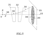
- the LiDAR system 18 comprises a wedge-shaped prism 21 being rotatable about a central axis 22 of the LiDAR system 18.
- the light beam 30 being emitted along the central axis 22 is deflected by the wedge-shaped prism 21 so that the light beam 30 after the prism 21 encloses an angle 23 with the central axis 22.
- the prism 21 is rotated the light beam 30 scans a circular scanning pattern 16 on the ground 15.
- the LiDAR LASER scanner 18 is formed by single rotating prism.
- the LASER beam 30 is deviated from the central axis 22 with an angle 23.
- the prim 21 is rotating at a given angular velocity, the beam intersects the plane 15 and forms the circle 16.
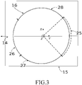
- the circular scanning path is divided in four sectors 25, 26, 27, 28.
- the error in the orientation or in the angle measurement of the prism 21 has the effect that the LiDAR system 18 provides roughly correct position data in two of the sectors, namely sectors 27, 28. In sector 25 the distance to the ground 15 is measured too short, in sector 26 the distance to the ground 15 is measured too long.
- position data is provided from an area on the ground 15, wherein the same positions on the ground 15 are first scanned with the measuring beam 30 being in sector 26 and later are scanned with the measuring beam 30 being in sector 25 of the scanning pattern 16.
- the coordinates of one and the same position on the ground 15 that are measured with in sector 25 will not match with the coordinates that are measured in sector 26, but the coordinates for one and the same position on the ground lie in two different parallel planes.
- the inventive method the mismatch between different sets of coordinates belonging to the same position on the ground is minimized.
- the measuring beam 30 has a plurality of different directions relative to the central axis 22 of the LiDAR system 18. Each of these directions is correlated with a distortion class. Each single point that is taken within the scanning pattern is tagged with a distortion class.
- the points of the point cloud sharing a first distortion class form a first subset of the point cloud
- the points of the point cloud sharing a second distortion class form a second subset of the point cloud and so on.
- the point cloud as measured provides coordinates in the aircraft-related coordinate system.
- the point cloud can be geo-referenced which means that each set of coordinates for a position on the ground is transformed from the aircraft-related coordinate system to the Earth-related coordinate system.
- a point cloud 47 obtained with the LiDAR system 18 of Fig. 2 is shown.
- the scanning pattern 16 is divided in five distortion classes 36-40. Based on the distortion classes 36-40 the points 43 of the point cloud 47 separated in five subsets of points 43.
- the points 43 in the first distortion class 36 form a first subset 44 of points 43 (marked with a star in Fig. 4 ).
- the points in the second distortion class 37 form a second subset 45 of points 43 (marked with a triangle).
- the points in the third distortion class 38 form a third subset 46 of points (marked with a dot).
- each of the subsets 44, 45, 46 of points covers a virtual strip 48 on the ground 15. Based on the overlapping regions 49 between the different virtual strips the strip adjustment step can be performed.
- the LiDAR system 18 has an optical system comprising a first optical element 31 in the form of a wedge-shaped prism and a second optical element 32 in the form of a wedge-shaped prism.
- the two optical elements 31, 32 are coaxially aligned and rotatable about the central axis 22 of the LiDAR system 18.
- Such arrangement of optical elements 31, 32 is called a Risley prim.
- both prisms have the same angular position so that the thick portions of both prisms 31, 32 as well as the thin portions of both prisms 31, 32 are aligned.
- the LASER beam 30 has a maximum deflection. If both prisms 31, 32 are rotated synchronously the light beam 30 describes a circular scanning pattern 16 on the ground 15.
- the circular scanning pattern 16 in the aligned state of the prisms 31, 32 corresponds to the envelope 20 of the LiDAR system 18.
- Fig. 6 the angular positions of the two prisms 31, 32 are separated by 180° so that the thin portion of the first prism 31 is aligned with the thick portion of the second prism 32 and vice versa.
- the light beam 30 undergoes a lateral shift and propagates in a direction parallel to the central axis 22 towards the ground 15.
- the circular scanning pattern 16 encloses a blind area 33 around the central axis 22, which is not accessible with the LiDAR system 18.
- the region between the envelope 20 and the blind area 33 corresponds to the scanning region 34 of the LiDAR system 18.
- a more complex scanning pattern 16 is generated between the envelope 20 and the blind area 33.
- One example of such scanning pattern 16 is shown in Fig. 7 .
- the exact form of the scanning pattern 16 depends on the ratio between the angular velocity of the first Risley prism 31 and the second Risley prism 32.
- the scanning pattern will be periodical if the ratio is rational, the scanning pattern will be non-periodical if the ratio is irrational.
- the ratio of the angular velocities can be adjusted so that the scanning region 34 of the LiDAR system 18 is densely covered with the scanning pattern 16. This enables the LiDAR system 18 to provide a substantially complete picture of the scanned region 34 without altering the position of the UAV 17 having the LiDAR system 18 on board.
- the two prisms 31, 32 can be rotated continuously during the measurement.
- the angular velocity of both prisms 31, 32 can be constant.
- a distortion map can be obtained, wherein the distortion map provides a level of distortion for each direction of the measuring beam 30 within the scanning region 34. If the level of distortion is defined on a relative scale the distortion can for example range from -1% to +1%. This means each direction of the measuring beam 30 within the scanning region 34 is correlated to a distortion level having a value between -1% and +1%. Based on the distortion level the beam directions can be classified in distortion classes.
- the first distortion class includes beam directions having a level of distortion between -1% and -0.5%
- the second distortion class includes levels of distortion between -0.5% and 0%
- the third distortion class includes levels of distortion between 0% and 0.5%
- the fourth distortion class includes levels of distortion between 0.5% and 1%.
- Fig. 8 a part of a scanning pattern 16 is shown, wherein different sections of the scanning pattern 16 are correlated with different distortion classes 35-42.
- Each set of coordinates from the ground 15 that is obtained with a measuring beam 30 being within one of the sections of the scanning pattern 16 is tagged with a distortion tag identifying the level of distortion according to distortion classes 35-42.
- FIG. 9 Another scanning pattern 16 having a simple periodic form is shown in Fig. 9 .
- the scanning pattern 16 is classified in six distortion classes 35-40.
- the points 43 sharing a common distortion class are marked with a common symbol (e.g., star, triangle). All the points having a common symbol form a subset of points of the point cloud obtained with the UAV 17 on survey line 14.
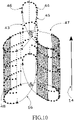
- three different subsets 44, 45, 46 are marked with reference numerals. The sum of all the subsets corresponds to the point cloud 47 obtained during the measurement along survey line 14.
- each subset 44, 45, 46 of points forms a virtual strip over the scanned region of the ground 15.
- the virtual strip of subset 46 of points is marked with reference 48 in Fig. 10 .
Landscapes
- Engineering & Computer Science (AREA)
- Remote Sensing (AREA)
- Physics & Mathematics (AREA)
- Radar, Positioning & Navigation (AREA)
- General Physics & Mathematics (AREA)
- Computer Networks & Wireless Communication (AREA)
- Electromagnetism (AREA)
- Automation & Control Theory (AREA)
- Optical Radar Systems And Details Thereof (AREA)
- Length Measuring Devices By Optical Means (AREA)
Priority Applications (5)
| Application Number | Priority Date | Filing Date | Title |
|---|---|---|---|
| EP20209260.7A EP4001841A1 (de) | 2020-11-23 | 2020-11-23 | Verfahren und system zur bestimmung von positionen auf dem boden aus einem luftfahrzeug |
| US18/037,729 US20230324555A1 (en) | 2020-11-23 | 2021-11-22 | Method and system for determining positions on the ground from an aerial vehicle |
| EP21816033.1A EP4248173A1 (de) | 2020-11-23 | 2021-11-22 | Verfahren und system zur bestimmung von positionen auf dem boden aus einem luftfahrzeug |
| PCT/EP2021/082442 WO2022106674A1 (en) | 2020-11-23 | 2021-11-22 | Method and system for determining positions on the ground from an aerial vehicle |
| CA3199117A CA3199117A1 (en) | 2020-11-23 | 2021-11-22 | Method and system for determining positions on the ground from an aerial vehicle |
Applications Claiming Priority (1)
| Application Number | Priority Date | Filing Date | Title |
|---|---|---|---|
| EP20209260.7A EP4001841A1 (de) | 2020-11-23 | 2020-11-23 | Verfahren und system zur bestimmung von positionen auf dem boden aus einem luftfahrzeug |
Publications (1)
| Publication Number | Publication Date |
|---|---|
| EP4001841A1 true EP4001841A1 (de) | 2022-05-25 |
Family
ID=73544072
Family Applications (2)
| Application Number | Title | Priority Date | Filing Date |
|---|---|---|---|
| EP20209260.7A Withdrawn EP4001841A1 (de) | 2020-11-23 | 2020-11-23 | Verfahren und system zur bestimmung von positionen auf dem boden aus einem luftfahrzeug |
| EP21816033.1A Withdrawn EP4248173A1 (de) | 2020-11-23 | 2021-11-22 | Verfahren und system zur bestimmung von positionen auf dem boden aus einem luftfahrzeug |
Family Applications After (1)
| Application Number | Title | Priority Date | Filing Date |
|---|---|---|---|
| EP21816033.1A Withdrawn EP4248173A1 (de) | 2020-11-23 | 2021-11-22 | Verfahren und system zur bestimmung von positionen auf dem boden aus einem luftfahrzeug |
Country Status (4)
| Country | Link |
|---|---|
| US (1) | US20230324555A1 (de) |
| EP (2) | EP4001841A1 (de) |
| CA (1) | CA3199117A1 (de) |
| WO (1) | WO2022106674A1 (de) |
Families Citing this family (1)
| Publication number | Priority date | Publication date | Assignee | Title |
|---|---|---|---|---|
| CN120018159B (zh) * | 2025-04-16 | 2025-07-18 | 南京信息工程大学 | 一种针对空中ris姿态变化的通信网络优化方法 |
Citations (1)
| Publication number | Priority date | Publication date | Assignee | Title |
|---|---|---|---|---|
| EP3739359A1 (de) * | 2019-05-17 | 2020-11-18 | Mitsubishi Heavy Industries, Ltd. | Laserradarvorrichtung, laserradarmessverfahren, laserradarmessprogramm und fahrzeug |
-
2020
- 2020-11-23 EP EP20209260.7A patent/EP4001841A1/de not_active Withdrawn
-
2021
- 2021-11-22 WO PCT/EP2021/082442 patent/WO2022106674A1/en not_active Ceased
- 2021-11-22 EP EP21816033.1A patent/EP4248173A1/de not_active Withdrawn
- 2021-11-22 CA CA3199117A patent/CA3199117A1/en active Pending
- 2021-11-22 US US18/037,729 patent/US20230324555A1/en not_active Abandoned
Patent Citations (1)
| Publication number | Priority date | Publication date | Assignee | Title |
|---|---|---|---|---|
| EP3739359A1 (de) * | 2019-05-17 | 2020-11-18 | Mitsubishi Heavy Industries, Ltd. | Laserradarvorrichtung, laserradarmessverfahren, laserradarmessprogramm und fahrzeug |
Non-Patent Citations (6)
| Title |
|---|
| CROMBAGHS M.J.E. ET AL: "On the adjustment of overlapping strips of laser altimeter height data", INTERNATIONAL ARCHIVES OF PHOTOGRAMMETRY AND REMOTE SENSING, VOL. XXXIII, PART B3, 1 January 2000 (2000-01-01), Amsterdam, XP055802161, Retrieved from the Internet <URL:https://www.isprs.org/PROCEEDINGS/XXXIII/congress/part3/230_XXXIII-part3.pdf> [retrieved on 20210506] * |
| GLIRA PHILIPP ET AL: "A Correspondence Framework for ALS Strip Adjustments based on Variants of the ICP Algorithm", PHOTOGRAMMETRIE, FERNERKUNDUNG, GEOINFORMATION, vol. 2015, no. 4, 1 August 2015 (2015-08-01), pages 275 - 289, XP055800377, ISSN: 1432-8364, Retrieved from the Internet <URL:https://www.dgpf.de/pfg/2015/pfg2015_4_glira.pdf> DOI: 10.1127/pfg/2015/0270 * |
| P. GLIRA ET AL.: "RIGOROUS STRIP ADJUSTMENT OF AIRBORNE LASERSCANNING DATA BASED ON THE ICP ALGORITHM", ISPRS ANNALS OF THE PHOTOGRAM-METRY, REMOTE SENSING AND SPATIAL INFORMATION SCIENCES, 2015, pages 73 - 80 |
| P. GLIRA ET AL.: "Rigorous Strip Adjustment of UAV-Based Laserscanning Data Including Time-Dependent Correction of Trajectory Errors", PHOTOGRAMMETRIC ENGI-NEERING AND REMOTE SENSING, vol. 82, 2016, pages 945 - 954 |
| WILLERS J ET AL: "A post-processing step error correction algorithm for overlapping LiDAR strips from agricultural landscapes", COMPUTERS AND ELECTRONICS IN AGRICULTURE, ELSEVIER, AMSTERDAM, NL, vol. 64, no. 2, 1 December 2008 (2008-12-01), pages 183 - 193, XP025532892, ISSN: 0168-1699, [retrieved on 20080624], DOI: 10.1016/J.COMPAG.2008.04.013 * |
| ZHANG YONGJUN ET AL: "LiDAR Strip Adjustment Using Multifeatures Matched With Aerial Images", IEEE TRANSACTIONS ON GEOSCIENCE AND REMOTE SENSING, IEEE SERVICE CENTER, PISCATAWAY, NJ, US, vol. 53, no. 2, 1 February 2015 (2015-02-01), pages 976 - 987, XP011556025, ISSN: 0196-2892, [retrieved on 20140812], DOI: 10.1109/TGRS.2014.2331234 * |
Also Published As
| Publication number | Publication date |
|---|---|
| CA3199117A1 (en) | 2022-05-27 |
| EP4248173A1 (de) | 2023-09-27 |
| WO2022106674A1 (en) | 2022-05-27 |
| US20230324555A1 (en) | 2023-10-12 |
Similar Documents
| Publication | Publication Date | Title |
|---|---|---|
| US10719076B1 (en) | Lead and follower aircraft navigation system | |
| Stöcker et al. | Quality assessment of combined IMU/GNSS data for direct georeferencing in the context of UAV-based mapping | |
| US9110170B1 (en) | Terrain aided navigation using multi-channel monopulse radar imaging | |
| US8872081B2 (en) | Methods for adjusting a relative navigation system | |
| KR102260239B1 (ko) | 지형 추적 비행방법 | |
| JP2021184280A (ja) | 航空機着陸システム及び方法 | |
| EP3851930B1 (de) | Looming-ball-pilotführung und cueing-symbologie | |
| CN114115353A (zh) | 一种编队避障方法及装置 | |
| Dolph et al. | Ground to air testing of a fused optical-radar aircraft detection and tracking system | |
| RU2513900C1 (ru) | Способ и устройство определения координат объектов | |
| Davidson et al. | Airborne to UAS LiDAR: An analysis of UAS LiDAR ground control targets | |
| KR102260240B1 (ko) | 지형 추적 비행방법 | |
| EP4001841A1 (de) | Verfahren und system zur bestimmung von positionen auf dem boden aus einem luftfahrzeug | |
| RU2483324C1 (ru) | Способ навигации летательного аппарата по радиолокационным изображениям земной поверхности | |
| Geister et al. | Flight testing of optimal remotely-piloted-aircraft-system scan patterns | |
| CN107942332B (zh) | 一种用于飞机着陆的双基sar成像系统空间同步方法 | |
| RU2564552C1 (ru) | Способ навигации летательного аппарата по радиолокационным изображениям земной поверхности | |
| EP3702870B1 (de) | System zur multispektralen objektidentifikation und entsprechendes verfahren | |
| Pepe | Survey by Airborne Laser Scanner of open large structure: A case study of Pompeii Amphitheatre | |
| US20190050001A1 (en) | System and method for precise determination of a remote geo-location in real time | |
| JP2007033258A (ja) | 被観測対象物の観測方法及び装置 | |
| Setterfield et al. | Real-World Testing of LiDAR-Inertial Based Navigation and Mapping for Precision Landing | |
| US20220034669A1 (en) | Navigation architecture for contested environments | |
| Baron et al. | ICC experiences on Inertial/GPS sensor orientation | |
| KR100571122B1 (ko) | 항공레이저측량시스템 보정을 위한 조정인자 산출방법 |
Legal Events
| Date | Code | Title | Description |
|---|---|---|---|
| PUAI | Public reference made under article 153(3) epc to a published international application that has entered the european phase |
Free format text: ORIGINAL CODE: 0009012 |
|
| STAA | Information on the status of an ep patent application or granted ep patent |
Free format text: STATUS: THE APPLICATION HAS BEEN PUBLISHED |
|
| AK | Designated contracting states |
Kind code of ref document: A1 Designated state(s): AL AT BE BG CH CY CZ DE DK EE ES FI FR GB GR HR HU IE IS IT LI LT LU LV MC MK MT NL NO PL PT RO RS SE SI SK SM TR |
|
| STAA | Information on the status of an ep patent application or granted ep patent |
Free format text: STATUS: THE APPLICATION IS DEEMED TO BE WITHDRAWN |
|
| 18D | Application deemed to be withdrawn |
Effective date: 20221126 |
|
| P01 | Opt-out of the competence of the unified patent court (upc) registered |
Effective date: 20230515 |