EP4001860A1 - Appareil de pesée par combinaison - Google Patents
Appareil de pesée par combinaison Download PDFInfo
- Publication number
- EP4001860A1 EP4001860A1 EP21204979.5A EP21204979A EP4001860A1 EP 4001860 A1 EP4001860 A1 EP 4001860A1 EP 21204979 A EP21204979 A EP 21204979A EP 4001860 A1 EP4001860 A1 EP 4001860A1
- Authority
- EP
- European Patent Office
- Prior art keywords
- articles
- discharge chute
- hopper
- slide
- slide surface
- Prior art date
- Legal status (The legal status is an assumption and is not a legal conclusion. Google has not performed a legal analysis and makes no representation as to the accuracy of the status listed.)
- Granted
Links
Images


Classifications
-
- G—PHYSICS
- G01—MEASURING; TESTING
- G01G—WEIGHING
- G01G19/00—Weighing apparatus or methods adapted for special purposes not provided for in the preceding groups
- G01G19/387—Weighing apparatus or methods adapted for special purposes not provided for in the preceding groups for combinatorial weighing, i.e. selecting a combination of articles whose total weight or number is closest to a desired value
-
- G—PHYSICS
- G01—MEASURING; TESTING
- G01G—WEIGHING
- G01G19/00—Weighing apparatus or methods adapted for special purposes not provided for in the preceding groups
- G01G19/387—Weighing apparatus or methods adapted for special purposes not provided for in the preceding groups for combinatorial weighing, i.e. selecting a combination of articles whose total weight or number is closest to a desired value
- G01G19/393—Weighing apparatus or methods adapted for special purposes not provided for in the preceding groups for combinatorial weighing, i.e. selecting a combination of articles whose total weight or number is closest to a desired value using two or more weighing units
-
- G—PHYSICS
- G01—MEASURING; TESTING
- G01G—WEIGHING
- G01G19/00—Weighing apparatus or methods adapted for special purposes not provided for in the preceding groups
- G01G19/22—Weighing apparatus or methods adapted for special purposes not provided for in the preceding groups for apportioning materials by weighing prior to mixing them
- G01G19/32—Weighing apparatus or methods adapted for special purposes not provided for in the preceding groups for apportioning materials by weighing prior to mixing them using two or more weighing apparatus
-
- B—PERFORMING OPERATIONS; TRANSPORTING
- B65—CONVEYING; PACKING; STORING; HANDLING THIN OR FILAMENTARY MATERIAL
- B65G—TRANSPORT OR STORAGE DEVICES, e.g. CONVEYORS FOR LOADING OR TIPPING, SHOP CONVEYOR SYSTEMS OR PNEUMATIC TUBE CONVEYORS
- B65G11/00—Chutes
- B65G11/16—Interior surfaces; Linings
- B65G11/163—Interior surfaces; Linings for articles
-
- G—PHYSICS
- G01—MEASURING; TESTING
- G01G—WEIGHING
- G01G21/00—Details of weighing apparatus
- G01G21/22—Weigh pans or other weighing receptacles; Weighing platforms
-
- B—PERFORMING OPERATIONS; TRANSPORTING
- B65—CONVEYING; PACKING; STORING; HANDLING THIN OR FILAMENTARY MATERIAL
- B65G—TRANSPORT OR STORAGE DEVICES, e.g. CONVEYORS FOR LOADING OR TIPPING, SHOP CONVEYOR SYSTEMS OR PNEUMATIC TUBE CONVEYORS
- B65G11/00—Chutes
- B65G11/16—Interior surfaces; Linings
- B65G11/166—Interior surfaces; Linings for bulk
Definitions
- the present invention relates to a combination weighing apparatus.
- an object of the invention is to provide a combination weighing apparatus capable of effectively implementing a countermeasure against adhesion of articles at low cost.
- a combination weighing apparatus is summarized as including: a plurality of hoppers that receives articles inputted from an outside, temporarily stores the articles, and discharges the stored articles downstream; a discharge chute that receives the articles discharged from the hoppers and causes the articles to slide downstream; an acquisition unit that acquires weight values of the articles stored in each hopper; and a control unit that performs combination calculation on the basis of the weight values acquired by the acquisition unit and discharges the articles from a hopper determined by the combination calculation to the discharge chute, wherein the discharge chute includes: a first slide surface having a plurality of openings; and a second slide surface that covers a part of the opening and is disposed at a position on an inner side of the discharge chute with respect to the first slide surface, and the second slide surface is formed continuously with the first slide surface on an upstream side, a left side, and a right side of the opening.
- a combination weighing apparatus is summarized as including: a plurality of hoppers that receives articles inputted from an outside, temporarily stores the articles, and discharge the stored articles downstream; a discharge chute that receives the articles discharged from the hoppers and causes the articles to slide downstream; an acquisition unit that acquires weight values of the articles stored in each hopper; and a control unit that performs combination calculation on the basis of the weight values acquired by the acquisition unit and discharges the articles from a hopper determined by the combination calculation to the discharge chute, wherein the discharge chute has a plurality of protrusions on a front surface on which the articles is conveyed, and an opening directed from the front surface to a rear surface is formed at an end portion on a downstream side of each of the plurality of protrusions.
- FIG. 1 is a diagram schematically illustrating the combination weighing apparatus 1 according to the present embodiment
- FIG. 2 is a diagram illustrating an example of a flow path surface on an inner side of a discharge chute 9 of the combination weighing apparatus 1 according to the present embodiment
- FIG. 3 is an enlarged view of an area A in FIG. 2
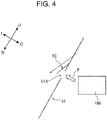
- FIG. 4 is a cross-sectional view taken along line X-X in FIG. 3 .
- the combination weighing apparatus 1 includes a dispersion feeder 2, n heads 40, a discharge chute 9, an acquisition unit 50, and a control unit 30.
- the n is a natural number of 1 or more, and may be a natural number of 2 or more.
- the n is 14, for example.
- the heads 40 are annularly arranged in top view.
- the heads 40 include a first head 40-1 to an n-th head 40-n.
- the first head 40-1 to the n-th head 40-n are arranged counterclockwise in top view in order of numbers.
- “annular” includes a toric shape, a polygonal ring shape, and the like.
- the present embodiment will explain the heads 40 that are annularly arranged as an example.
- Each of the heads 40 includes a radiation feeder 3, a pool hopper 4, a weighing hopper 5, a booster hopper 6, and a sorting chute 7. Accordingly, the radiation feeders 3, the pool hoppers 4, the weighing hoppers 5, the booster hoppers 6, and the sorting chutes 7 are each also annularly arranged in top view.
- the dispersion feeder 2 is a flat conical member.
- a supply conveyor 90 provided above the dispersion feeder 2 supplies articles to the dispersion feeder 2.
- the upper surface of the dispersion feeder 2 is vibrated by an electromagnet (not shown) provided below the dispersion feeder 2.
- the dispersion feeder 2 conveys the articles supplied to the upper surface in the radial direction while dispersing the articles in the circumferential direction, and supplies the articles to the respective radiation feeders 3.
- Each radiation feeder 3 is a sheet-metal member formed by bending a stainless steel plate.
- the radiation feeders 3 are arranged radially along the periphery of the dispersion feeder 2.
- each radiation feeder 3 the conveyance surface is configured to be vibrated by an electromagnet (not shown) provided below the radiation feeder 3.
- Each radiation feeder 3 is configured to convey the articles outward with the vibration of the conveyance surface.
- each radiation feeder 3 is configured to supply the articles to the pool hopper 4 of the head 40 to which the radiation feeder itself belongs.
- the conveying ability of the radiation feeder 3 can be adjusted by the vibration strength (vibration amplitude) and the vibration time on the conveyance surface. Accordingly, by adjusting the vibration strength and the vibration time, the weight values of the articles supplied to each pool hopper 4 can be kept within a predetermined range.
- Each pool hopper 4 is disposed below the tip portion of the corresponding radiation feeder 3. Each pool hopper 4 is configured to temporarily hold or discharge the articles supplied from the radiation feeder 3.
- the pool hopper 4 is provided with a gate 4a that opens and closes a bottom portion of the pool hopper 4, and a stepping motor (not shown) that drives the gate 4a.
- the gate 4a is caused to perform an opening/closing operation by the control unit 30 controlling the stepping motor.
- the pool hopper 4 is configured to hold the articles inside the pool hopper 4 in a state where the gate 4a is close, and discharge the articles to the weighing hopper 5 of the head 40 to which the pool hopper itself belongs in a state where the gate 4a is open.
- the weighing hopper 5 is configured to temporarily receive the articles so as to weigh the articles, and sort and discharge the weighed articles in one of the first direction FD or the second direction SD.
- Each weighing hopper 5 is disposed immediately below the pool hopper 4 of the head 40 to which the weighing hopper itself belongs.
- the weighing hopper 5 is configured to hold the articles supplied from the pool hopper 4, and weigh the weight values of such articles.
- the weighing hopper 5 is provided with gates 5a and 5b that open and close a bottom portion of the weighing hopper 5, and a stepping motor (not shown) that drives the gates 5a and 5b.
- the weighing hopper 5 is configured to hold the articles inside in a state where both the gates 5a and 5b are close. Such a state is a state where the weighing hopper 5 temporarily receives articles.
- the weighing hopper 5 is configured to sort and discharge the weighed articles in one of the first direction FD or the second direction SD by opening one of the gates 5a or 5b.
- the weighing hopper 5 is configured to sort and discharge the articles in the first direction FD and discharge the articles to the booster hopper 6 of the head 40 to which the weighing hopper itself belongs, in a state where the gate 5b is open.
- the weighing hopper 5 is configured to sort and discharge the articles in the second direction SD and discharge the articles to the sorting chute 7 of the head 40 to which the weighing hopper itself belongs, in a state where the gate 5a is open.
- the booster hopper 6 is configured to temporarily receive the articles discharged in the first direction FD, and discharge the received articles downstream.
- Each booster hopper 6 is disposed below a position close to the center of the combination weighing apparatus 1 in the weighing hopper 5 of the head 40 to which the booster hopper itself belongs.
- the booster hopper 6 is configured to temporarily hold or discharge the articles supplied from the weighing hopper 5.
- the booster hopper 6 has a gate 6a that can open and close. Specifically, the booster hopper 6 is provided with a gate 6a that opens and closes a bottom portion of the booster hopper 6.
- the booster hopper 6 is configured to hold the articles inside in a state where the gate 6a is close. This state is a state where the booster hopper 6 temporarily receives the articles.
- the booster hopper 6 is configured to discharge the articles to the discharge chute 9 in a state where the gate 6a is open.
- the booster hopper 6 may be provided with a weighing sensor, so that the weight values of the articles stored in the booster hopper 6 can be weighed.
- the weighing hoppers 5 and the booster hoppers 6 constitute a plurality of hoppers that receive the articles inputted from the outside, temporarily store the articles, and then discharge the articles downstream.
- the sorting chute 7 is configured to discharge the articles discharged in the second direction SD downstream. Each sorting chute 7 is disposed below a position close to the outer side of the combination weighing apparatus 1 in the weighing hopper 5 of the head 40 to which the sorting chute itself belongs.
- the position of the sorting chute 7 is switched by a drive unit.
- the sorting chute 7 is configured to discharge the articles discharged in the second direction SD to the discharge chute 9 at the first position, and is configured to discharge the articles discharged in the second direction SD to the outer side (outside the system) of the discharge chute 9 at the second position.
- the discharge chute 9 the articles discharged from the booster hoppers 6 and the sorting chutes 7 slide down. That is, the discharge chute 9 is configured to discharge such articles downstream.
- the discharge chute 9 is configured to collect the articles discharged from the weighing hopper 5 and the booster hopper 6 determined by combination calculation by the control unit 30 to be described later to one place and discharge the articles downward.
- the articles discharged from the discharge chute 9 are supplied to a subsequent packaging device or the like.
- the discharge chute 9 is configured to receive the articles discharged from the weighing hopper 5 and the booster hopper 6 described above and cause the articles to slide downstream.
- the acquisition unit 50 is configured to acquire the weight values of the articles stored in each weighing hopper 5 and each booster hopper 6.
- the acquisition unit 50 may be configured to acquire the weight values measured by the weighing sensor of the weighing hopper 5 as the weight values of the articles stored in the weighing hopper 5.
- the acquisition unit 50 may be configured to acquire the weight values weighed by the weighing sensor in a case where the booster hopper 6 is provided with a weighing sensor, and acquire the weight values of the articles stored in the weighing hopper 5 acquired immediately before the weighing hopper 5 opens the gate 5b to sort and discharge the articles in the first direction FD as the weight values of the articles stored in the booster hopper 6 in a case where the booster hopper 6 is not provided with a weighing sensor.
- the control unit 30 is configured to perform combination calculation on the basis of the weight values of the articles acquired by the acquisition unit 50 and discharge the articles from the weighing hopper 5 and the booster hopper 6 determined by the combination calculation to the discharge chute 9.
- FIG. 2 illustrates the discharge chute 9 in a state of being developed such that the flow path surface on the inner side I faces upward. As illustrated in FIG. 2 , the entire surface of the flow path surface on the inner side I of the discharge chute 9 is subjected to the louver processing.
- the present embodiment will hereinafter explain a case where the louver processing is carried out on the flow path surface on the inner side I of the discharge chute 9 as an example, the present invention is not limited to such a case, and can be applied to a case where the louver processing is carried out on an any surface (flow path surface) on which an article slides down by its own weight, such as the inner side I of the dispersion feeder 2, the radiation feeders 3, the pool hoppers 4 (gates 4a), the weighing hoppers 5 (gates 5a and 5b), the booster hoppers 6 (gates 6a), the sorting chutes 7, or the like.
- the discharge chute 9 has a first slide surface 91 and second slide surfaces 92.
- the first slide surface 91 has a plurality of openings 91A.
- each second slide surface 92 is configured to cover a part of an opening 91A. Moreover, as illustrated in FIG. 4 , each second slide surface 92 is disposed at a position on the inner side I of the discharge chute 9 with respect to the first slide surface 91.
- each second slide surface 92 is formed continuously with the first slide surface 91 on the upstream side U, the left side L, and the right side R of an opening 91A.
- each second slide surface 92 has a left flat surface 92L, a right flat surface 92R, and an upper flat surface 92U.
- each left flat surface 92L is formed so as to rise from the first slide surface 91 toward the inner side I on the left side L of an opening 91A.
- each right flat surface 92R is formed so as to rise from the first slide surface 91 toward the inner side I on the right side R of an opening 91A.
- each upper flat surface 92U is formed to connect a left flat surface 92L with a right flat surface 92R.
- the discharge chute 9 has a plurality of protrusions 92 on the front surface 91 on which articles are conveyed, and openings 91A directed from such a front surface 91 toward a rear surface 93 are formed at end portions 92E on the downstream side of the plurality of protrusions 92.
- the second slide surfaces (protrusions) 92 each constituted by a left flat surface 92L, a right flat surface 92R, and an upper flat surface 92U, it is possible to decrease the contact area between an article (an object to be weighed) having high adhesion and the flow path surface of the discharge chute 9, to reduce the adhesion of the article, and to reduce the weighing error.
- each second slide surface 92 is provided with a left flat surface 92L and a right flat surface 92R, it is possible to reduce a situation in which moisture contained in the article leaks to the outer side O of the discharge chute 9.
- the combination weighing apparatus 1 may further have a jet unit 100.
- the jet unit 100 is configured to jet air from the outer side O toward the inner side I of the discharge chute 9 in the openings 91A.
- the air jetted by the jet unit 100 can further reduce the adhesion of the articles.
Landscapes
- Physics & Mathematics (AREA)
- General Physics & Mathematics (AREA)
- Supply Of Fluid Materials To The Packaging Location (AREA)
- Weight Measurement For Supplying Or Discharging Of Specified Amounts Of Material (AREA)
- Filling Or Emptying Of Bunkers, Hoppers, And Tanks (AREA)
- Basic Packing Technique (AREA)
Applications Claiming Priority (1)
| Application Number | Priority Date | Filing Date | Title |
|---|---|---|---|
| JP2020188747A JP7597357B2 (ja) | 2020-11-12 | 2020-11-12 | 組合せ計量装置 |
Publications (3)
| Publication Number | Publication Date |
|---|---|
| EP4001860A1 true EP4001860A1 (fr) | 2022-05-25 |
| EP4001860B1 EP4001860B1 (fr) | 2025-02-12 |
| EP4001860C0 EP4001860C0 (fr) | 2025-02-12 |
Family
ID=78621671
Family Applications (1)
| Application Number | Title | Priority Date | Filing Date |
|---|---|---|---|
| EP21204979.5A Active EP4001860B1 (fr) | 2020-11-12 | 2021-10-27 | Appareil de pesée par combinaison |
Country Status (4)
| Country | Link |
|---|---|
| US (1) | US11927470B2 (fr) |
| EP (1) | EP4001860B1 (fr) |
| JP (1) | JP7597357B2 (fr) |
| CN (1) | CN114485881B (fr) |
Cited By (1)
| Publication number | Priority date | Publication date | Assignee | Title |
|---|---|---|---|---|
| EP4431885A1 (fr) * | 2023-03-13 | 2024-09-18 | Ishida Co., Ltd. | Appareil de pesage combinatoire |
Families Citing this family (2)
| Publication number | Priority date | Publication date | Assignee | Title |
|---|---|---|---|---|
| JP7587817B2 (ja) * | 2020-11-27 | 2024-11-21 | 株式会社イシダ | 物品処理装置及び下流側装置 |
| JP2025070194A (ja) * | 2023-10-19 | 2025-05-02 | 株式会社イシダ | 搬送装置 |
Citations (3)
| Publication number | Priority date | Publication date | Assignee | Title |
|---|---|---|---|---|
| WO2014067533A1 (fr) | 2012-11-02 | 2014-05-08 | Marel A/S | Structure de plaque à surface anticollante destinée à être utilisée comme un matériau de base à faible friction dans un appareil de transformation des aliments et procédé permettant la fabrication de celle-ci |
| WO2018139127A1 (fr) * | 2017-01-27 | 2018-08-02 | 大和製衡株式会社 | Dispositif d'alimentation vibrant et dispositif d'alimentation d'article l'utilisant |
| KR102100468B1 (ko) * | 2019-06-17 | 2020-04-13 | 전병선 | 원료가 달라붙지 않는 조합계량기 |
Family Cites Families (15)
| Publication number | Priority date | Publication date | Assignee | Title |
|---|---|---|---|---|
| US1416073A (en) * | 1919-11-05 | 1922-05-16 | John J Steinbach | Coal chute |
| US3895982A (en) * | 1970-12-15 | 1975-07-22 | Trelleborgs Gummifabriks Ab | Wear protection elements for planar or curved surfaces exposed to abrasion |
| AU543793B2 (en) * | 1981-09-09 | 1985-05-02 | K.K. Ishida Koki Seisakusho | Preventing adhesion of weighed material |
| JPS59151123U (ja) * | 1983-03-28 | 1984-10-09 | 大和製衡株式会社 | 計量ホツパ内面に対する粉状物付着防止装置 |
| US4561509A (en) * | 1983-12-20 | 1985-12-31 | House Food Industrial Company, Limited | Combination weighing machine |
| JP2537921Y2 (ja) * | 1991-02-04 | 1997-06-04 | 株式会社三和自動機製作所 | 製袋充填包装装置 |
| JP3194821B2 (ja) * | 1993-08-10 | 2001-08-06 | 株式会社イシダ | 自動計量装置の集合シュート |
| DE69530472T2 (de) * | 1994-08-26 | 2003-10-30 | Anritsu Industrial Solutions Co., Ltd. | Kombinationswaage |
| JP3505131B2 (ja) | 2000-05-30 | 2004-03-08 | 株式会社タクマ | 炉内への被処理物投入シュート |
| JP2004352433A (ja) | 2003-05-29 | 2004-12-16 | Sanwa Trading Kk | 泥状体の流動促進装置 |
| JP6112976B2 (ja) | 2013-06-03 | 2017-04-12 | 日清フーズ株式会社 | 充填装置 |
| JP2019090717A (ja) * | 2017-11-15 | 2019-06-13 | 株式会社イシダ | 組合せ計量装置 |
| JP7061796B2 (ja) * | 2018-08-31 | 2022-05-02 | 株式会社イシダ | 組合せ計量装置 |
| KR102136067B1 (ko) * | 2018-11-09 | 2020-07-21 | 주식회사 포스코 | 슈트 부착탄 제거 장치 |
| JP7765067B2 (ja) * | 2021-08-31 | 2025-11-06 | 株式会社イシダ | 搬送装置 |
-
2020
- 2020-11-12 JP JP2020188747A patent/JP7597357B2/ja active Active
-
2021
- 2021-10-27 EP EP21204979.5A patent/EP4001860B1/fr active Active
- 2021-10-27 US US17/511,666 patent/US11927470B2/en active Active
- 2021-11-10 CN CN202111326253.4A patent/CN114485881B/zh active Active
Patent Citations (3)
| Publication number | Priority date | Publication date | Assignee | Title |
|---|---|---|---|---|
| WO2014067533A1 (fr) | 2012-11-02 | 2014-05-08 | Marel A/S | Structure de plaque à surface anticollante destinée à être utilisée comme un matériau de base à faible friction dans un appareil de transformation des aliments et procédé permettant la fabrication de celle-ci |
| WO2018139127A1 (fr) * | 2017-01-27 | 2018-08-02 | 大和製衡株式会社 | Dispositif d'alimentation vibrant et dispositif d'alimentation d'article l'utilisant |
| KR102100468B1 (ko) * | 2019-06-17 | 2020-04-13 | 전병선 | 원료가 달라붙지 않는 조합계량기 |
Cited By (1)
| Publication number | Priority date | Publication date | Assignee | Title |
|---|---|---|---|---|
| EP4431885A1 (fr) * | 2023-03-13 | 2024-09-18 | Ishida Co., Ltd. | Appareil de pesage combinatoire |
Also Published As
| Publication number | Publication date |
|---|---|
| JP2022077761A (ja) | 2022-05-24 |
| US11927470B2 (en) | 2024-03-12 |
| JP7597357B2 (ja) | 2024-12-10 |
| CN114485881A (zh) | 2022-05-13 |
| BR102021021850A2 (pt) | 2022-05-24 |
| CN114485881B (zh) | 2025-02-25 |
| EP4001860B1 (fr) | 2025-02-12 |
| EP4001860C0 (fr) | 2025-02-12 |
| US20220146301A1 (en) | 2022-05-12 |
Similar Documents
| Publication | Publication Date | Title |
|---|---|---|
| EP4001860B1 (fr) | Appareil de pesée par combinaison | |
| US10525509B2 (en) | Installation for sorting articles with a sorting conveyor having pivotally mounted flaps | |
| CN108394702B (zh) | 槟榔装盘机构 | |
| EP3098580A1 (fr) | Appareil de pesée combiné | |
| US6605785B1 (en) | Combinatorial weighing and counting device with multi-part collecting chute | |
| EP3617671A1 (fr) | Dispositif de pesage par combinaison | |
| EP4246105B1 (fr) | Appareil de pesage combinatoire | |
| EP4140918B1 (fr) | Appareil de transport | |
| WO2001002251A1 (fr) | Procede et dispositif permettant de trier et d'emballer des objets | |
| CN113494953B (zh) | 计量装置 | |
| BR102021021850B1 (pt) | Aparelho de pesagem de combinação | |
| EP3964805B1 (fr) | Dispositif de pesage par combinaison | |
| US10837821B2 (en) | Combination weighing apparatus including small and large units including weighing hoppers | |
| CN108423405B (zh) | 槟榔装盘用识别联动传感装置及槟榔装盘机构 | |
| EP3882587B1 (fr) | Appareil de pesage | |
| US10408669B2 (en) | Combination weighing device | |
| US11866268B2 (en) | Article conveyance device and combination weighing device | |
| US20250237540A1 (en) | Combination weighing apparatus | |
| EP4431885A1 (fr) | Appareil de pesage combinatoire | |
| EP3995793B1 (fr) | Appareil de transport d'articles | |
| EP4030152A1 (fr) | Dispositif de pesage par combinaison | |
| JP2024025187A (ja) | 搬送装置及び組合せ計量システム | |
| EP4589268A1 (fr) | Appareil de pesage combinatoire | |
| JP7162886B2 (ja) | 組合せ計量装置 | |
| WO2025219723A1 (fr) | Appareil de pesage de combinaison informatique |
Legal Events
| Date | Code | Title | Description |
|---|---|---|---|
| PUAI | Public reference made under article 153(3) epc to a published international application that has entered the european phase |
Free format text: ORIGINAL CODE: 0009012 |
|
| STAA | Information on the status of an ep patent application or granted ep patent |
Free format text: STATUS: REQUEST FOR EXAMINATION WAS MADE |
|
| 17P | Request for examination filed |
Effective date: 20211027 |
|
| AK | Designated contracting states |
Kind code of ref document: A1 Designated state(s): AL AT BE BG CH CY CZ DE DK EE ES FI FR GB GR HR HU IE IS IT LI LT LU LV MC MK MT NL NO PL PT RO RS SE SI SK SM TR |
|
| REG | Reference to a national code |
Ref country code: DE Ref legal event code: R079 Free format text: PREVIOUS MAIN CLASS: G01G0019387000 Ipc: G01G0019393000 Ref document number: 602021025920 Country of ref document: DE |
|
| GRAP | Despatch of communication of intention to grant a patent |
Free format text: ORIGINAL CODE: EPIDOSNIGR1 |
|
| STAA | Information on the status of an ep patent application or granted ep patent |
Free format text: STATUS: GRANT OF PATENT IS INTENDED |
|
| RIC1 | Information provided on ipc code assigned before grant |
Ipc: G01G 19/393 20060101AFI20240902BHEP |
|
| INTG | Intention to grant announced |
Effective date: 20240913 |
|
| GRAS | Grant fee paid |
Free format text: ORIGINAL CODE: EPIDOSNIGR3 |
|
| GRAA | (expected) grant |
Free format text: ORIGINAL CODE: 0009210 |
|
| STAA | Information on the status of an ep patent application or granted ep patent |
Free format text: STATUS: THE PATENT HAS BEEN GRANTED |
|
| AK | Designated contracting states |
Kind code of ref document: B1 Designated state(s): AL AT BE BG CH CY CZ DE DK EE ES FI FR GB GR HR HU IE IS IT LI LT LU LV MC MK MT NL NO PL PT RO RS SE SI SK SM TR |
|
| REG | Reference to a national code |
Ref country code: GB Ref legal event code: FG4D |
|
| REG | Reference to a national code |
Ref country code: CH Ref legal event code: EP |
|
| REG | Reference to a national code |
Ref country code: DE Ref legal event code: R096 Ref document number: 602021025920 Country of ref document: DE |
|
| REG | Reference to a national code |
Ref country code: IE Ref legal event code: FG4D |
|
| U01 | Request for unitary effect filed |
Effective date: 20250214 |
|
| U07 | Unitary effect registered |
Designated state(s): AT BE BG DE DK EE FI FR IT LT LU LV MT NL PT RO SE SI Effective date: 20250220 |
|
| PG25 | Lapsed in a contracting state [announced via postgrant information from national office to epo] |
Ref country code: RS Free format text: LAPSE BECAUSE OF FAILURE TO SUBMIT A TRANSLATION OF THE DESCRIPTION OR TO PAY THE FEE WITHIN THE PRESCRIBED TIME-LIMIT Effective date: 20250512 |
|
| PG25 | Lapsed in a contracting state [announced via postgrant information from national office to epo] |
Ref country code: PL Free format text: LAPSE BECAUSE OF FAILURE TO SUBMIT A TRANSLATION OF THE DESCRIPTION OR TO PAY THE FEE WITHIN THE PRESCRIBED TIME-LIMIT Effective date: 20250212 |
|
| PG25 | Lapsed in a contracting state [announced via postgrant information from national office to epo] |
Ref country code: ES Free format text: LAPSE BECAUSE OF FAILURE TO SUBMIT A TRANSLATION OF THE DESCRIPTION OR TO PAY THE FEE WITHIN THE PRESCRIBED TIME-LIMIT Effective date: 20250212 |
|
| PG25 | Lapsed in a contracting state [announced via postgrant information from national office to epo] |
Ref country code: NO Free format text: LAPSE BECAUSE OF FAILURE TO SUBMIT A TRANSLATION OF THE DESCRIPTION OR TO PAY THE FEE WITHIN THE PRESCRIBED TIME-LIMIT Effective date: 20250512 Ref country code: IS Free format text: LAPSE BECAUSE OF FAILURE TO SUBMIT A TRANSLATION OF THE DESCRIPTION OR TO PAY THE FEE WITHIN THE PRESCRIBED TIME-LIMIT Effective date: 20250612 |
|
| PG25 | Lapsed in a contracting state [announced via postgrant information from national office to epo] |
Ref country code: HR Free format text: LAPSE BECAUSE OF FAILURE TO SUBMIT A TRANSLATION OF THE DESCRIPTION OR TO PAY THE FEE WITHIN THE PRESCRIBED TIME-LIMIT Effective date: 20250212 |
|
| PG25 | Lapsed in a contracting state [announced via postgrant information from national office to epo] |
Ref country code: GR Free format text: LAPSE BECAUSE OF FAILURE TO SUBMIT A TRANSLATION OF THE DESCRIPTION OR TO PAY THE FEE WITHIN THE PRESCRIBED TIME-LIMIT Effective date: 20250513 |
|
| PG25 | Lapsed in a contracting state [announced via postgrant information from national office to epo] |
Ref country code: SM Free format text: LAPSE BECAUSE OF FAILURE TO SUBMIT A TRANSLATION OF THE DESCRIPTION OR TO PAY THE FEE WITHIN THE PRESCRIBED TIME-LIMIT Effective date: 20250212 |
|
| PG25 | Lapsed in a contracting state [announced via postgrant information from national office to epo] |
Ref country code: CZ Free format text: LAPSE BECAUSE OF FAILURE TO SUBMIT A TRANSLATION OF THE DESCRIPTION OR TO PAY THE FEE WITHIN THE PRESCRIBED TIME-LIMIT Effective date: 20250212 |
|
| PG25 | Lapsed in a contracting state [announced via postgrant information from national office to epo] |
Ref country code: SK Free format text: LAPSE BECAUSE OF FAILURE TO SUBMIT A TRANSLATION OF THE DESCRIPTION OR TO PAY THE FEE WITHIN THE PRESCRIBED TIME-LIMIT Effective date: 20250212 |
|
| U20 | Renewal fee for the european patent with unitary effect paid |
Year of fee payment: 5 Effective date: 20251027 |
|
| PLBE | No opposition filed within time limit |
Free format text: ORIGINAL CODE: 0009261 |
|
| STAA | Information on the status of an ep patent application or granted ep patent |
Free format text: STATUS: NO OPPOSITION FILED WITHIN TIME LIMIT |
|
| PGFP | Annual fee paid to national office [announced via postgrant information from national office to epo] |
Ref country code: GB Payment date: 20251024 Year of fee payment: 5 |
|
| 26N | No opposition filed |
Effective date: 20251113 |