EP4001896A1 - Système technique de traitement biologique destiné aux essais de filtration - Google Patents
Système technique de traitement biologique destiné aux essais de filtration Download PDFInfo
- Publication number
- EP4001896A1 EP4001896A1 EP20209610.3A EP20209610A EP4001896A1 EP 4001896 A1 EP4001896 A1 EP 4001896A1 EP 20209610 A EP20209610 A EP 20209610A EP 4001896 A1 EP4001896 A1 EP 4001896A1
- Authority
- EP
- European Patent Office
- Prior art keywords
- filtration test
- sensor
- filter
- data
- test system
- Prior art date
- Legal status (The legal status is an assumption and is not a legal conclusion. Google has not performed a legal analysis and makes no representation as to the accuracy of the status listed.)
- Granted
Links
Images


Classifications
-
- B—PERFORMING OPERATIONS; TRANSPORTING
- B01—PHYSICAL OR CHEMICAL PROCESSES OR APPARATUS IN GENERAL
- B01L—CHEMICAL OR PHYSICAL LABORATORY APPARATUS FOR GENERAL USE
- B01L3/00—Containers or dishes for laboratory use, e.g. laboratory glassware; Droppers
- B01L3/50—Containers for the purpose of retaining a material to be analysed, e.g. test tubes
- B01L3/502—Containers for the purpose of retaining a material to be analysed, e.g. test tubes with fluid transport, e.g. in multi-compartment structures
- B01L3/5027—Containers for the purpose of retaining a material to be analysed, e.g. test tubes with fluid transport, e.g. in multi-compartment structures by integrated microfluidic structures, i.e. dimensions of channels and chambers are such that surface tension forces are important, e.g. lab-on-a-chip
- B01L3/502753—Containers for the purpose of retaining a material to be analysed, e.g. test tubes with fluid transport, e.g. in multi-compartment structures by integrated microfluidic structures, i.e. dimensions of channels and chambers are such that surface tension forces are important, e.g. lab-on-a-chip characterised by bulk separation arrangements on lab-on-a-chip devices, e.g. for filtration or centrifugation
-
- B—PERFORMING OPERATIONS; TRANSPORTING
- B01—PHYSICAL OR CHEMICAL PROCESSES OR APPARATUS IN GENERAL
- B01D—SEPARATION
- B01D61/00—Processes of separation using semi-permeable membranes, e.g. dialysis, osmosis or ultrafiltration; Apparatus, accessories or auxiliary operations specially adapted therefor
- B01D61/14—Ultrafiltration; Microfiltration
- B01D61/22—Controlling or regulating
-
- B—PERFORMING OPERATIONS; TRANSPORTING
- B01—PHYSICAL OR CHEMICAL PROCESSES OR APPARATUS IN GENERAL
- B01D—SEPARATION
- B01D61/00—Processes of separation using semi-permeable membranes, e.g. dialysis, osmosis or ultrafiltration; Apparatus, accessories or auxiliary operations specially adapted therefor
- B01D61/14—Ultrafiltration; Microfiltration
- B01D61/20—Accessories; Auxiliary operations
-
- B—PERFORMING OPERATIONS; TRANSPORTING
- B01—PHYSICAL OR CHEMICAL PROCESSES OR APPARATUS IN GENERAL
- B01D—SEPARATION
- B01D65/00—Accessories or auxiliary operations, in general, for separation processes or apparatus using semi-permeable membranes
- B01D65/10—Testing of membranes or membrane apparatus; Detecting or repairing leaks
-
- B—PERFORMING OPERATIONS; TRANSPORTING
- B01—PHYSICAL OR CHEMICAL PROCESSES OR APPARATUS IN GENERAL
- B01L—CHEMICAL OR PHYSICAL LABORATORY APPARATUS FOR GENERAL USE
- B01L3/00—Containers or dishes for laboratory use, e.g. laboratory glassware; Droppers
- B01L3/50—Containers for the purpose of retaining a material to be analysed, e.g. test tubes
- B01L3/502—Containers for the purpose of retaining a material to be analysed, e.g. test tubes with fluid transport, e.g. in multi-compartment structures
- B01L3/5027—Containers for the purpose of retaining a material to be analysed, e.g. test tubes with fluid transport, e.g. in multi-compartment structures by integrated microfluidic structures, i.e. dimensions of channels and chambers are such that surface tension forces are important, e.g. lab-on-a-chip
- B01L3/502715—Containers for the purpose of retaining a material to be analysed, e.g. test tubes with fluid transport, e.g. in multi-compartment structures by integrated microfluidic structures, i.e. dimensions of channels and chambers are such that surface tension forces are important, e.g. lab-on-a-chip characterised by interfacing components, e.g. fluidic, electrical, optical or mechanical interfaces
-
- B—PERFORMING OPERATIONS; TRANSPORTING
- B01—PHYSICAL OR CHEMICAL PROCESSES OR APPARATUS IN GENERAL
- B01L—CHEMICAL OR PHYSICAL LABORATORY APPARATUS FOR GENERAL USE
- B01L3/00—Containers or dishes for laboratory use, e.g. laboratory glassware; Droppers
- B01L3/50—Containers for the purpose of retaining a material to be analysed, e.g. test tubes
- B01L3/502—Containers for the purpose of retaining a material to be analysed, e.g. test tubes with fluid transport, e.g. in multi-compartment structures
- B01L3/5027—Containers for the purpose of retaining a material to be analysed, e.g. test tubes with fluid transport, e.g. in multi-compartment structures by integrated microfluidic structures, i.e. dimensions of channels and chambers are such that surface tension forces are important, e.g. lab-on-a-chip
- B01L3/502738—Containers for the purpose of retaining a material to be analysed, e.g. test tubes with fluid transport, e.g. in multi-compartment structures by integrated microfluidic structures, i.e. dimensions of channels and chambers are such that surface tension forces are important, e.g. lab-on-a-chip characterised by integrated valves
-
- G—PHYSICS
- G01—MEASURING; TESTING
- G01N—INVESTIGATING OR ANALYSING MATERIALS BY DETERMINING THEIR CHEMICAL OR PHYSICAL PROPERTIES
- G01N1/00—Sampling; Preparing specimens for investigation
- G01N1/02—Devices for withdrawing samples
- G01N1/22—Devices for withdrawing samples in the gaseous state
- G01N1/2202—Devices for withdrawing samples in the gaseous state involving separation of sample components during sampling
- G01N1/2205—Devices for withdrawing samples in the gaseous state involving separation of sample components during sampling with filters
-
- G—PHYSICS
- G01—MEASURING; TESTING
- G01N—INVESTIGATING OR ANALYSING MATERIALS BY DETERMINING THEIR CHEMICAL OR PHYSICAL PROPERTIES
- G01N15/00—Investigating characteristics of particles; Investigating permeability, pore-volume or surface-area of porous materials
- G01N15/08—Investigating permeability, pore-volume, or surface area of porous materials
- G01N15/082—Investigating permeability by forcing a fluid through a sample
- G01N15/0826—Investigating permeability by forcing a fluid through a sample and measuring fluid flow rate, i.e. permeation rate or pressure change
-
- B—PERFORMING OPERATIONS; TRANSPORTING
- B01—PHYSICAL OR CHEMICAL PROCESSES OR APPARATUS IN GENERAL
- B01D—SEPARATION
- B01D2311/00—Details relating to membrane separation process operations and control
- B01D2311/24—Quality control
-
- B—PERFORMING OPERATIONS; TRANSPORTING
- B01—PHYSICAL OR CHEMICAL PROCESSES OR APPARATUS IN GENERAL
- B01D—SEPARATION
- B01D2313/00—Details relating to membrane modules or apparatus
- B01D2313/90—Additional auxiliary systems integrated with the module or apparatus
- B01D2313/903—Integrated control or detection device
-
- B—PERFORMING OPERATIONS; TRANSPORTING
- B01—PHYSICAL OR CHEMICAL PROCESSES OR APPARATUS IN GENERAL
- B01L—CHEMICAL OR PHYSICAL LABORATORY APPARATUS FOR GENERAL USE
- B01L2200/00—Solutions for specific problems relating to chemical or physical laboratory apparatus
- B01L2200/06—Fluid handling related problems
- B01L2200/0684—Venting, avoiding backpressure, avoid gas bubbles
-
- B—PERFORMING OPERATIONS; TRANSPORTING
- B01—PHYSICAL OR CHEMICAL PROCESSES OR APPARATUS IN GENERAL
- B01L—CHEMICAL OR PHYSICAL LABORATORY APPARATUS FOR GENERAL USE
- B01L2200/00—Solutions for specific problems relating to chemical or physical laboratory apparatus
- B01L2200/12—Specific details about manufacturing devices
-
- B—PERFORMING OPERATIONS; TRANSPORTING
- B01—PHYSICAL OR CHEMICAL PROCESSES OR APPARATUS IN GENERAL
- B01L—CHEMICAL OR PHYSICAL LABORATORY APPARATUS FOR GENERAL USE
- B01L2200/00—Solutions for specific problems relating to chemical or physical laboratory apparatus
- B01L2200/16—Reagents, handling or storing thereof
-
- B—PERFORMING OPERATIONS; TRANSPORTING
- B01—PHYSICAL OR CHEMICAL PROCESSES OR APPARATUS IN GENERAL
- B01L—CHEMICAL OR PHYSICAL LABORATORY APPARATUS FOR GENERAL USE
- B01L2300/00—Additional constructional details
- B01L2300/06—Auxiliary integrated devices, integrated components
- B01L2300/0627—Sensor or part of a sensor is integrated
- B01L2300/0663—Whole sensors
-
- B—PERFORMING OPERATIONS; TRANSPORTING
- B01—PHYSICAL OR CHEMICAL PROCESSES OR APPARATUS IN GENERAL
- B01L—CHEMICAL OR PHYSICAL LABORATORY APPARATUS FOR GENERAL USE
- B01L2300/00—Additional constructional details
- B01L2300/06—Auxiliary integrated devices, integrated components
- B01L2300/0681—Filter
-
- B—PERFORMING OPERATIONS; TRANSPORTING
- B01—PHYSICAL OR CHEMICAL PROCESSES OR APPARATUS IN GENERAL
- B01L—CHEMICAL OR PHYSICAL LABORATORY APPARATUS FOR GENERAL USE
- B01L2300/00—Additional constructional details
- B01L2300/08—Geometry, shape and general structure
- B01L2300/0861—Configuration of multiple channels and/or chambers in a single devices
- B01L2300/087—Multiple sequential chambers
-
- B—PERFORMING OPERATIONS; TRANSPORTING
- B01—PHYSICAL OR CHEMICAL PROCESSES OR APPARATUS IN GENERAL
- B01L—CHEMICAL OR PHYSICAL LABORATORY APPARATUS FOR GENERAL USE
- B01L2400/00—Moving or stopping fluids
- B01L2400/04—Moving fluids with specific forces or mechanical means
- B01L2400/0475—Moving fluids with specific forces or mechanical means specific mechanical means and fluid pressure
- B01L2400/0478—Moving fluids with specific forces or mechanical means specific mechanical means and fluid pressure pistons
-
- B—PERFORMING OPERATIONS; TRANSPORTING
- B01—PHYSICAL OR CHEMICAL PROCESSES OR APPARATUS IN GENERAL
- B01L—CHEMICAL OR PHYSICAL LABORATORY APPARATUS FOR GENERAL USE
- B01L2400/00—Moving or stopping fluids
- B01L2400/06—Valves, specific forms thereof
-
- G—PHYSICS
- G01—MEASURING; TESTING
- G01N—INVESTIGATING OR ANALYSING MATERIALS BY DETERMINING THEIR CHEMICAL OR PHYSICAL PROPERTIES
- G01N15/00—Investigating characteristics of particles; Investigating permeability, pore-volume or surface-area of porous materials
- G01N15/08—Investigating permeability, pore-volume, or surface area of porous materials
- G01N2015/084—Testing filters
-
- G—PHYSICS
- G01—MEASURING; TESTING
- G01N—INVESTIGATING OR ANALYSING MATERIALS BY DETERMINING THEIR CHEMICAL OR PHYSICAL PROPERTIES
- G01N15/00—Investigating characteristics of particles; Investigating permeability, pore-volume or surface-area of porous materials
- G01N15/08—Investigating permeability, pore-volume, or surface area of porous materials
- G01N2015/0846—Investigating permeability, pore-volume, or surface area of porous materials by use of radiation, e.g. transmitted or reflected light
Definitions
- the invention relates to a bioprocess engineering, in particular biopharmaceutical, filtration test system according to the preamble of claim 1, a data receiving instrument for use in such a bioprocess engineering filtration test system according to the preamble of claim 18 and a use of a packaged filtration test kit made of pre-assembled system components for the construction of such a bioprocess engineering filtration test system according to Preamble of claim 20.
- a bioprocess engineering filtration test system is generally understood to mean a system with which small-scale filtration tests are carried out with a liquid, for example biological, in particular biopharmaceutical, test medium.
- a filtration test system can generally be used to record the flow as a function of the pressure, to measure the behavior with different wetting media as pretreatment, to determine the service life (duration until blocking) or the like.
- a filtration trials system can be used to find suitable filters for larger scale filtration, for example for industrial production of biopharmaceuticals.
- test data namely sensor data from pressure sensors, for example, is determined for at least one filter or at least one combination of filter and wetting medium, on the basis of which the filter and/or the wetting medium of a target system can be selected and/or dimensioned according to predetermined scaling criteria.
- a filtration test system can be used to select the filter size or filter surface that is optimal for a specific filtration process, optionally with a wetting medium that is optimal for it.
- a specified amount of the test medium is filtered with a filter of a specified size, if necessary using a specific wetting medium, with the pressure and volume flow of the test medium being recorded and documented by sensors as it passes through the filtration test section.
- one variable for example the pressure
- the other variable for example the volume flow
- the user basically has to mechanically and fluidically connect a large number of components, in particular sensors and filters.
- the sensors must also be electrically connected to an appropriate data receiving instrument.
- a drive for the liquid test medium for example a pump or a supply line for providing compressed air, in particular together with a pneumatic pressure regulator, must be connected fluidically and, if necessary, electrically.
- a drive for air for emptying the fluid lines of the filtration test system for example a pump or a supply line for providing compressed air, in particular with a pneumatic pressure regulator, can also be provided, with a fluid and possibly electrical connection also having to be made here.
- the term "pump” is to be understood broadly in the present case and includes not only machines for pumping liquids (hydraulic pumps, e.g. peristaltic pumps) but also gases (pneumatic pumps, e.g. compressors).
- the invention is based on the problem of designing and developing the known bioprocess engineering filtration test system in such a way that its handling is simplified.
- the fundamental consideration is to reduce the number of work steps to be carried out by the user when planning and constructing the system by pre-assembling at least individual components of the filtration test system.
- This can be done by a and/or circuitry pre-assembly, ie pre-assembly of software required for a specific filtration test and/or an electrical circuit, in particular an integrated circuit, required for this.
- a fluid-technical pre-assembly can also be provided, ie a pre-assembly of components through which the test medium can flow, such as filters, valves and/or line sections.
- a sensor-related pre-assembly can also be provided, ie a pre-assembly relating to the sensors of the filtration test system.
- Pre-assembly means that several of the aforementioned components such as filters, valves, sensors, fluid lines or the like have already been selected for a specific experiment, i.e. suitable for a specific filtration experiment, and pre-assembled into a unit, in particular by the manufacturer. Such a preassembled unit is also referred to below as an assembly module.
- pre-assembly means that the software or electrical circuit is provided for a specific filtration test on a test-specific basis. This considerably simplifies the planning and construction of the filtration test system.
- the filtration test system be at least partially pre-assembled in terms of programming and/or circuitry, at least partially fluidically and/or at least partially in terms of sensors.
- Claim 2 defines particularly preferred components and parts of the filtration test system and in particular of the filtration test section.
- the filtration test section is defined here as the section of the filtration test system through which the test medium flows, beginning with the storage tank and ending at the outlet.
- Particularly preferred components are in particular a valve arrangement, a sensor arrangement, a filter arrangement, a fluid line network, a data receiving instrument and/or a weighing arrangement. Accordingly, particularly preferred components are valves, sensors, filters and line sections.
- a data receiving instrument is a device that is set up at least to receive sensor data from the sensor arrangement. This is, for example, data from one or more pressure sensors, volume flow sensors, conductivity sensors, optical sensors, e.g. turbidity sensors, UV sensors, infrared and/or Raman sensors, temperature sensors, etc.
- the data receiving instrument can also be used to process the sensor data and/or as a control unit , be set up to control a pump and/or a pneumatic pressure regulator of the filtration test system or one or more valves of the valve arrangement.
- a corresponding control is carried out in particular on the basis of control data which are generated, at least in part, by processing the sensor data.
- the respective control is then based on the sensor data.
- the processing of the sensor data and/or the control of the pump and/or the pneumatic pressure regulator and/or the respective valve, the respective data receiving instrument is pre-assembled in particular in terms of programming and/or circuitry.
- the respective software and/or electrical circuitry of the data receiving instrument is therefore adapted to a specific type of filtration test (e.g. "constant pressure” or “constant flow”) or even filtration test or prepared for a specific filtration test.
- pump is to be understood broadly and not only for machines for pumping liquids, hereinafter referred to as “hydraulic pumps” (e.g. peristaltic pumps), but also for gases, hereinafter referred to as “pneumatic pumps”. (eg compressors) includes.
- a pump can be provided in the proposed filtration test system as a drive for the liquid test medium and/or as a drive for air, for example for emptying the fluid lines of the proposed filtration test system.
- the drive for the liquid test medium and/or the drive for air can also be an external compressed air source, in particular an external compressed air network, an external compressed air bottle or the like, optionally with a pneumatic pressure regulator interposed in terms of fluid technology to regulate the external compressed air source.
- Claim 7 defines preferred pre-assemblies of the filtration test system.
- a particularly preferred embodiment relates to the pre-assembly of the filtration test system, in that the measuring principle, the specifications and/or the installation position of at least one sensor are matched to a specific filtration test or prepared for a specific filtration test.
- a pre-assembly is a sensor-technical pre-assembly.
- a further particularly preferred embodiment relates to the pre-assembly of the filtration test system, in that the functional principle, the specifications and/or the installation position of at least one filter are matched to a specific filtration test or prepared for a specific filtration test.
- a pre-assembly is a fluid-technical pre-assembly.
- Yet another particularly preferred embodiment relates to the prefabrication of the filtration test system, in that the type of actuation, the specifications and/or the installation position of at least one valve is/are matched to a specific filtration test or is/are prepared for a specific filtration test.
- a pre-assembly is also a fluid-technical pre-assembly.
- Yet another particularly preferred embodiment relates to the prefabrication of the filtration test system, in that the specifications and/or the installation position of at least one line section is/are matched to a specific filtration test or is/are prepared for a specific filtration test.
- a pre-assembly is also a fluid-technical pre-assembly.
- a fluid technology and/or sensor technology pre-assembly is carried out by one or more assembly modules, ie pre-assembled units of components of the filtration test system, in particular the filtration test section.
- the use of such assembly modules simplifies assembly and thus the commissioning, but also the dismantling, for example for transport.
- the respective assembly module has at least one or more line sections of the fluid line network and at least one other of the components “sensor”, “filter” and “valve”.
- An assembly module is also conceivable which, in addition to one of the components “sensor”, “filter”, “valve” and “line section”, has a reservoir. The selection of the components that are pre-assembled to the assembly module is then tailored to a specific filtration test.
- An assembly module can already be formed by one of the components "sensor”, “filter”, “valve” and “reservoir” being connected to a line section of the fluid line network as intended.
- "intended” means a connection that has been completed in accordance with the intended application.
- such an assembly module particularly preferably includes at least two of the components "sensor”, “filter”, “valve” and “reservoir”, so that, for example, a reservoir and a sensor and/or two sensors can be connected to each other as intended via a line section are connected.
- the components connected to one another as intended are fixed to one another solely by a line section, ie without using a separate support structure to which the respective component is attached.
- the respective assembly module is preferably a single-use component, ie a disposable component. If the single-use components are replaced accordingly, there is no need to clean the components and there is no risk of contamination in two consecutive filtration tests with different test media.
- the assembly modules described are designed in particular in such a way that several assembly modules with an identical structure and/or assembly modules with a different structure can be connected to one another mechanically, pneumatically, hydraulically and/or electrically via at least one corresponding interface connect to each other.
- the assembly modules have a support structure or a housing, these can be stacked in particular vertically one above the other (claim 12).
- the filtration test system has a carrier on which the respective storage container and/or one or more sensors, valves and/or assembly modules can be fixed or fixed.
- the carrier can be a tripod, in particular a rod-shaped or plate-shaped tripod, with a holder, in particular a height-adjustable one.
- the carrier is a mounting plate, in particular fastened to a stand, for example a rod-shaped or plate-shaped stand, on which the respective storage container and/or the respective sensor and/or the respective mounting module can be or is fixed.
- the respective component for example the respective reservoir and/or the respective sensor, preferably has a fastening section with a magnet, the mounting plate being magnetic at least at the points provided for fastening the respective sensor or being made entirely of metal, in particular is designed.
- a magnet is provided at the locations provided for the attachment of the respective sensor, the sensor then having a magnetic attachment section, in particular made of metal.
- a form-fitting and/or force-fitting fixation can also be provided. Such a fixation can be done, for example, by a clamp or plug connection between the respective sensor and the mounting plate.
- the mounting plate is preferably part of a housing of a data receiving instrument as defined above, in particular the data receiving instrument, which is set up to process the sensor data, bundle the sensor data into data packets and send the data packets and/or convert analog sensor data into digital sensor data and/or , in particular before the conversion, to carry out an amplification of the analog sensor signals (claim 16).
- a data receiving instrument as defined above, in particular the data receiving instrument, which is set up to process the sensor data, bundle the sensor data into data packets and send the data packets and/or convert analog sensor data into digital sensor data and/or , in particular before the conversion, to carry out an amplification of the analog sensor signals (claim 16).
- Claim 17 defines that the respective carrier and/or the respective stand can be mechanically connected to the housing of a scale of the weighing arrangement.
- a data receiving instrument for use in a bioprocess engineering, in particular biopharmaceutical, filtration test system for filtering a liquid test medium as part of a filtration test in a filtration test section of the filtration test system which consists of a storage container for receiving the to be filtered Test medium leads to an outlet for the filtered test medium claimed.
- the data receiving instrument is set up to receive sensor data of a sensor arrangement generated as part of the filtration test as test data for at least one filter, in particular also to record and/or process it, on the basis of which the filter of a target system can be selected and/or dimensioned according to predetermined scaling criteria. It may insofar on the Statements on the proposed bioprocess engineering filtration test system are referenced.
- Claim 19 relates to a particularly preferred embodiment according to which the data receiving instrument can automatically recognize the start and/or end of a filtration test. This can be done by activating a flow rate sensor at the start of the test, which is accompanied by the creation of a flow, or by deactivating a volume flow sensor at the end of the test, which is accompanied by the flow being stopped.
- the filtration test set in the packaging has at least one assembly module consisting of at least one line section of the fluid line network, which is connected as intended to at least one sensor of the sensor arrangement, at least one filter of the filter arrangement and/or at least one valve of the valve arrangement.
- a reservoir which is preferably fluidically connected to the line section, can also be provided as part of the assembly module.
- the filtration test set is unpacked, ie removed from the packaging, and mechanically, fluidically and/or electrically connected to other system components.
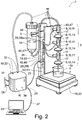
- the filtration test systems 1 shown in each case are used to filter a liquid, here for example biological, test medium M in a filtration test section 2 of the filtration test system 1.
- the filtration test section 2 leads from a storage container 3 for receiving the test medium M to be filtered to a fluid outlet 4a, from which the filtered test medium F (Filtrate) reaches a collection container 5.
- the collection container 5 is not included in the filtration test section 2 here.
- the filtration test section 2 begins with the storage tank 3, then extends downstream and ends with the fluid outlet 4a.
- the filtration test system 1 is set up, as part of a filtration test, sensor data as test data for at least one filter 6 of the filtration test section 2 to determine. On the basis of the test data, according to predetermined scaling criteria, a corresponding filter of a target system can be selected and/or dimensioned for the respective filter 6 of the filtration test section 2 for which the test data were determined.
- the filtration test system 1 is at least partially prefabricated in terms of programming and/or circuitry, at least partially fluidically and/or at least partially with sensors.
- Pre-assembled in terms of programming and/or circuitry means that a software and/or electrical circuit, in particular an integrated circuit, which is provided in the filtration test system 1, is designed test-specifically.
- Fluid-technically pre-assembled means that a unit of fluid-technically, i.e. pneumatically and/or hydraulically, through-flowable components of the filtration test system 1, in particular the filtration test section 2, is designed test-specifically.
- Pre-assembled sensor technology means that the sensor system of the filtration test system 1 is designed test-specifically.
- the filtration test systems 1 explained here by way of example, in particular the filtration test sections 2, preferably have a valve arrangement 7 with one or more valves 8, a sensor arrangement 9 with one or more sensors 10, in particular one or more pressure sensors 11, volume flow sensors 12 (also flow sensors or called flow sensors) and/or temperature sensors, a filter arrangement 13 with one or more filters 6, for example flat filters, in particular liquid filters 14 and/or air filters 15, for example a vent valve, and/or a fluid line network 16 with a number of line sections 17, via which the Test medium M reaches the respective filter 6, 14 on.
- the liquid filters 14 are the filters for which the test data are determined
- the air filters 15 that may be present serve only as an aid for wetting the respective liquid filter 14 .
- the sensors 10, 11, 12, the filters 6, 14, 15 and the line sections 17 are preferably single-use components.
- the same preferably applies at least to the filters 6, 14 in the exemplary embodiment according to FIG 2 and the embodiment according to 3 and 4 .
- the valves 8 can also be designed as single-use components.
- the line sections 17 are also designed as single-use components, with line sections 17 between the sensor 9 and the filter 6 preferably also being able to be dispensed with.
- the or the storage container 3 preferably single-use components.
- the filtration test system 1 here and preferably, as in the embodiments of Figures 1 to 4 shown, at least one data receiving instrument 18 for receiving sensor data from the sensor arrangement 9 .
- the filtration test system 1 here and preferably, as in the embodiments of Figures 2 to 4 shown, a weighing arrangement 19 with a scale 20 .
- the data receiving instrument 18 in the embodiment in FIG 1 a device 21 which, in addition to receiving sensor data, also allows the sensor data to be recorded, ie the sensor data to be recorded.
- the data receiving instrument 18 in the form of the device 21 is here and preferably set up to automatically detect the start of a filtration test and to automatically start recording the sensor data and/or to automatically detect the end of a filtration test and to automatically end the recording of the sensor data.
- the test medium M is set in motion here by pressurization, whereby the volume flow sensor 12 is activated, in particular a measuring wheel (vane wheel) of the volume flow sensor 12 begins to rotate, and the data receiving instrument 18 recognizes the start of the test on the basis of the corresponding sensor data. Conversely, the volume flow sensor 12 is deactivated or the measuring wheel of the volume flow sensor 12 stops turning, as soon as no more test medium M flows through it, the data receiving instrument 18 then recognizing the end of the test on the basis of the corresponding sensor data or a lack of further sensor data.
- the volume flow sensor 12 is activated, in particular a measuring wheel (vane wheel) of the volume flow sensor 12 begins to rotate, and the data receiving instrument 18 recognizes the start of the test on the basis of the corresponding sensor data.
- the volume flow sensor 12 is deactivated or the measuring wheel of the volume flow sensor 12 stops turning, as soon as no more test medium M flows through it, the data receiving instrument 18 then recognizing the end of the test on the basis of the corresponding sensor data or a lack
- a hydraulic pump for example a peristaltic pump, can also be provided for transporting the test medium M.
- the respective data receiving instrument 18 in the form of device 21 is here and preferably also set up to read out the received sensor data, which is raw data here, as test data from a separate data processing and/or evaluation device, for example an external computer (not shown here). allow.
- the data receiving instrument 18 according to FIG 1 after recording sensor data from one or more filtration tests, possibly after pre-processing, for example in the form of smoothing and/or averaging some or all of the sensor data, the user sends it to the manufacturer of the filtration test system 1 for evaluation.
- a data cable (not shown here) can be connected to the device 21, which connects the device 21 to the data processing and/or evaluation device or computer.
- the data processing and/or evaluation device or the computer then recognizes the device 21 in particular as a drive which enables the stored sensor data to be copied, moved and/or deleted.
- a corresponding filter of a target system can then be selected and/or dimensioned according to predetermined scaling criteria for the respective filter 6, 14 of the filtration test section 2.
- the filtration test system 1 has two different data receiving instruments 18 .
- One data receiving instrument 18 is a control unit 22, which, in addition to receiving and, if necessary, acquiring sensor data, also allows the sensor data to be processed, specifically here and preferably in such a way that, based on the sensor data, a pneumatic pressure regulator R between the compressed air source and storage tank 3 can be controlled .
- a pneumatic pressure regulator R between the compressed air source and storage tank 3 can be controlled .
- a pump can also be controlled based on the sensor data.
- the processing of the sensor data includes a comparison of the sensor data with at least one desired value or desired value range, in particular for pressure sensor data and/or volume flow sensor data.
- the pressure of the compressed air is then regulated here via the pneumatic pressure regulator R in such a way that in the filtration test system 1, in particular in the filtration test section 2, there is a predetermined, constant or varying pressure or volume flow of the test medium M and/or the compressed air and/or a wetting liquid B and / or a rinsing liquid adjusts.
- the pump can also be controlled in such a way that in the filtration test system 1, in particular in the filtration test section 2, a predetermined, constant or varying pressure or volume flow of the test medium M and/or the compressed air and/or a Wetting liquid B and / or a rinsing liquid adjusts.
- the test types “constant pressure” and “constant flow” can be operated via the pneumatic pressure regulator R, which can be integrated into the control unit 22 .
- the pressure of the test medium M is kept at a constant value during the filtration test.
- the volume flow of the test medium M is kept at a constant value during the filtration test.
- this can also be achieved via a pneumatic pump connected fluidically upstream of the storage tank 3 and optionally integrated in the control unit 22 or a hydraulic pump (not shown here) connected fluidically between the storage tank 3 and the filtration test section 2 .
- test types with varying pressure of the test medium M and varying volume flow of the test medium M are also conceivable.
- filtration tests in which first the "constant pressure” test type and then the "constant flow” test type, or vice versa.
- the data receiving instrument 18 in the form of the control unit 22 can in principle also be set up to automatically recognize the start of a filtration attempt and automatically start the control and/or to automatically recognize the end of a filtration attempt and automatically end the control.
- an external computer 26 is provided, which is connected to the data receiving instrument 18 or control unit 22 via a data cable 27 or a wireless connection and via which the user can determine the start and/or end of the test.
- the control unit 22 is spatially spaced here and preferably from the filtration test section 2 and the balance 20 and in particular also from a carrier 42 or stand 43 described below and can preferably also be placed independently of them. “Spatially spaced” means that there is a vertical and/or horizontal distance from the components of the filtration test section 2, from the balance 20 and, in particular, also from the carrier 42 or stand 43.
- the other data receiving instrument 18 in 2 is a device 23, which also enables the sensor data to be processed in addition to the acquisition of sensor data, with the processing of the sensor data here bundling sensor data into data packets and sending the data packets and/or converting analog sensor data into digital sensor data and/or, in particular prior to converting, amplifying the analog sensor signals.
- the data receiving instrument 18 in the form of the device 23 is here and preferably also set up to record the configuration of the sensor arrangement 9, in particular the number of sensors 10, 11, 12 and/or the position of the sensors 10, 11, 12 on the device 23 and/or in the filtration section and/or the measuring principle of the sensors 10, 11, 12, and preferably to carry out the above processing of the sensor data as a function thereof.
- the sensor data processed by device 23 are then forwarded to control device 22 .
- the device 23 is arranged here and preferably adjacent to and along the filtration test section 2 and is in mechanical contact with the sensors 10 , ie not at a spatial distance from the filtration test section 2 .
- the device 23 is also in mechanical contact with the stand 43 , ie not at a spatial distance from the stand 43 . Therefore, the device 23 cannot be placed independently of the filtration test section 2 and/or the stand 43 either.
- a data receiving instrument 18 is also provided in the form of the control unit 22 described above, which, in addition to receiving and possibly acquiring sensor data, also enables processing of the sensor data for controlling a pneumatic pressure regulator R, in particular internal to the device. Additionally or alternatively, the data receiving instrument 18 or control unit 22 can also process the sensor data to control valves 8 of the valve arrangement 7 and/or a pump, in particular external to the device, for example a hydraulic pump for conveying the test medium M and/or a pneumatic pump 24, which supplies compressed air to the Emptying and cleaning of the fluid line network 16 of the filtration test section 2 generated allow.
- the terms "device-external” and “device-internal” always refer to the control unit 22 here.
- control unit 22 controls the valves 8 of the valve arrangement 7 and/or the pump, for example a hydraulic pump and/or pneumatic pump 24, via a control cable 25 which is connected to the control unit 22.
- the respective data receiving instrument 18 in the form of the control unit 22 is here and preferably also set up to transmit the received sensor data, which can be raw data or sensor data that has already been processed, and/or the sensor data processed by the control unit 22 itself as test data to a separate data processing and/or or evaluation device, for example an external computer 26 to transmit.
- a data cable for this 27 or a wireless connection is provided, which can connect the control device 22 to the data processing and/or evaluation device or computer 26 in each case.
- a corresponding filter of a target system can be selected and/or dimensioned for the respective filter 6, 14 of the filtration test section 2 via the data processing and/or evaluation device or the computer 26.
- pre-assembly options are conceivable for the proposed filtration test system 1, namely programming and/or circuitry pre-assembly and/or fluid-technical pre-assembly and/or sensor-technical pre-assembly. These pre-assembly options are explained in more detail below.
- all data receiving instruments 18 relating to the reception of sensor data of the sensor arrangement 9 are pre-assembled in terms of programming and/or circuitry.
- the data receiving instrument 18 in the form of the in 1 shown device 21 also relating to the acquisition of sensor data of the sensor arrangement 9 programming and / or circuitry prefabricated.
- the data receiving instrument 18 in the form of the 2 and 3 The control unit 22 shown is prefabricated in terms of programming and/or circuitry for processing sensor data of the sensor arrangement 9, here and preferably in such a way that the processing of the sensor data includes a comparison of the sensor data with at least one target value or target value range.
- the data receiving instrument 18 in the form of the device 23 is also prefabricated in terms of programming and/or circuitry for the processing of sensor data from the sensor arrangement 9, here and preferably in such a way that the processing of the sensor data involves bundling sensor data into data packets and sending the data packets, namely to the control unit 22, and/or, if it is analog sensors 10, 11, 12, for example, converting analog sensor data into digital sensor data and/or, in particular before the conversion, amplifying the analog sensor signals.
- the data receiving instrument 18 shown in the form of the control unit 22 is prefabricated here and preferably also with regard to the control of the pneumatic pressure regulator R and/or the pump in terms of programming and/or circuitry.
- the data receiving instrument 18 or control unit 22 relating to the control of the pneumatic pressure regulator R integrated in the control unit 22 is prefabricated in terms of programming and/or circuitry.
- the data receiving instrument 18 or control unit 22 relating to the control of a pump, here for example the pneumatic pump 24, which is provided downstream of the control unit 22, must be prefabricated in terms of programming and/or circuitry.
- the pneumatic pressure regulator R and/or the optionally present pump can be controlled here and preferably as follows.
- a predetermined, constant or varying pressure or volume flow of the test medium M in the filtration test section 2 and/or, in the exemplary embodiment according to 3 and 4 A defined, constant or varying pressure or volume flow of a wetting liquid B, in particular in an automatic filter wetting process, can be generated in the filtration test section 2 .
- a defined, constant or varying pressure or volume flow of the compressed air and/or a flushing liquid generated by the pump 24 can be generated in the filtration test section 2, in particular during an automatic emptying and/or flushing process.
- the data receiving instrument 18 in the form of the control unit 22 according to the embodiment in 3 relating to the control of one or more valves 8 of the valve assembly 7 programmed and / or circuitry prefabricated is provided here in particular with regard to the control of the respective valve 8 during a filter wetting process, during a filter venting process, during a filtration test with the test medium M and/or during an emptying and/or rinsing process.
- the respective data receiving instrument 18 is preferably provided with a power supply 28 and/or at least one data interface 29, at least for receiving (data input 29a) and optionally also for reading or outputting (data output 29b) sensor data.
- the data receiving instrument 18 in the form of the in 1 The device 21 shown is, if sensor data can be recorded with it, also provided in particular with a memory 30 for storing raw sensor data and/or processed sensor data. Such a memory 30 is also optionally available for the data receiving instrument 18 in the form of the in 2 and 3 illustrated control unit 22 is provided. That in the 2 and 3
- the data receiving instrument 18 shown in the form of the control unit 22 also has a pneumatic inlet 31 and at least one pneumatic outlet 32 .
- a pneumatic pressure regulator R is also integrated into the control unit 22, which connects the inlet 31 to the outlet 32 and preferably generates a constant pressure or a pressure that causes a constant volume flow in order to supply either the test medium M or the to conduct wetting liquid B through the filtration test section 2.
- the respective data receiving instrument 18 is preferably free of hydraulic connections.
- the respective data receiving instrument 18 is also spatially separated from the filtration test section 2 and, at least in the case of the device 21 and/or the control unit 22, spatially separated from the scales 20 and in particular also spatially separated from a carrier 42 or Stand 43 can be arranged.
- a sensor-technical pre-assembly is provided here and preferably with regard to the measuring principle, the specifications and/or the installation position of at least one sensor 10 of the sensor arrangement 9 .
- sensors are divided into pressure sensors, volume flow sensors and temperature sensors, for example.
- Specifications are the technical ones and functional aspects, including in particular the dimensions, of the respective sensor 10 are meant.
- the specifications also include, for example, the maximum measurement deviation, the standard measurement error, the temperature dependency, etc.
- the “installation position” refers to the respective position of the sensor 10 within the filtration test system 1, in particular within the filtration test section 2.
- Examples of the installation position are, for example, a point before or after a specific other component of the filtration test section 2, in the case of a volume flow sensor or pressure sensor, for example, a point upstream of a filter 6, in particular a filter 6, for which the test data are determined.
- a fluid-technical pre-assembly is provided here and preferably with regard to the functional principle, the specifications and/or the installation position of at least one filter 6, 14, 15 of the filter arrangement 13.
- Filters are divided into liquid filters and air filters and/or surface filters, deep-bed filters, precoat filters etc. according to the functional principle.
- “Specifications” mean the technical and functional aspects, including in particular the dimensions, of the respective filter 6, 14, 15.
- the specifications also include, for example, the filter medium (fabric, paper, fleece, fibers, grains), the initial pressure loss, etc.
- the "installation position” refers to the respective position of the filter 6, 14, 15 within the filtration test system 1 , in particular within the filtration test section 2. Examples of the installation position are, for example, a point in front of or behind a certain other component of the filtration test section 2, for example a point downstream of a sensor 10.
- a fluid-technical prefabrication is provided here and preferably with regard to the type of actuation, the specifications and/or the installation position of at least one valve 8 of the valve arrangement 7 .
- valves are divided into manually operated, motor-operated, magnetically operated valves, etc., for example.
- “Specifications” mean the technical and functional aspects, including in particular the dimensions, of the valve 8 in question.
- the specifications also include, for example, the type of sealing materials (hard/soft sealing), the position of the seal (on the piston/in the housing), the seal structure, etc.
- the "installation position” designates the respective position of the valve 8 within the filtration test system 1, in particular within the filtration test section 2. Examples of the installation position are, for example, a point in front of or behind a specific other component of the filtration test section 2, for example a point upstream or downstream of a filter 6.
- a fluid-technical prefabrication is provided here and preferably with regard to the specifications and/or the installation position of at least one line section 17 of the fluid line network 16 .
- “Specifications” mean the technical and functional aspects, including in particular the dimensions, of the respective line section 17 . In the case of a line section 17, the specifications also include, for example, the type of material, rigidity, transparency, etc.
- the "installation position” refers to the respective position of the line section 17 within the filtration test system 1, in particular within the filtration test section 2. Examples of the installation position are, for example, a Place before or after a certain other component of the filtration test section 2, for example a place upstream or downstream of a filter 6.
- a particularly preferred form of pre-assembly can be achieved by providing assembly modules 33, i.e. in particular by means of units pre-assembled by the manufacturer with a plurality of components connected to one another as intended, in particular selected from the group comprising the components “sensor”, “filter”, “valve” and “line section ".
- Further components of an assembly module 33 can be a storage container 3 and/or a pump, in particular a hydraulic pump and/or a pneumatic pump 24, and/or, in particular in a housing 34, a circuit board 35.
- At least one reservoir 3, at least one sensor 10 of the sensor arrangement 9 and/or at least one valve 8 of the valve arrangement 7 together with at least one line section 17 of the fluid line network 16 form an assembly module 33 that is pre-assembled in terms of fluid technology and/or sensor technology.
- At least one Assembly module 33 or several such assembly modules 33 form the filtration test section 2.
- the respective assembly module 33 can also have the storage container 3 for the test medium M and/or a storage container 3 for wetting liquid (B) and/or rinsing liquid.
- In 1 1 shows an assembly module 33 consisting of a storage container 3 for the medium M, a volume flow sensor 10, 12 and a line section 17 as an example.
- the entirety of storage container 3, volume flow sensor 10, 12, pressure sensor 10, 11 and corresponding line sections 17 can also form an assembly module 33, which is also shown.
- the respective sensor 10, 11, 12 can also already be connected to the respectively assigned data cable, which is then also part of the respective assembly module 33.
- the individual assembly modules 33 have no additional support structure.
- a support structure is provided in the form of a housing 34 of the respective assembly module 33, here and preferably in the form of a plastic, resin, glass, ceramic and/or metal housing.
- the housing 34 serves to accommodate at least one sensor 10 of the sensor arrangement 9, at least one filter 6, 14, 15 of the filter arrangement 13, at least one valve 8 of the valve arrangement 7 and/or at least one line section 17 of the fluid line network 16.
- the assembly module 33 then forms in each case a block, namely either a so-called connection block, or a so-called extension block or a so-called basic block.
- a connection block is here and preferably a structural unit with a housing 34, in or on which several components necessary for the construction of a filtration test section 2, e.g. one or more valves 8 and/or line sections 17, are functionally installed, but this unit is not here Possibility of connecting a filter 6, 14, for which test data are to be determined. In the installed state, so if the filtration test track is ready for use, this unit is used here solely for the connection of one or more pneumatic, hydraulic and/or electrical lines for the corresponding supply of all downstream blocks in terms of the flow direction of the test medium M in terms of fluid technology.
- the test medium M is introduced via the connection block into all blocks and/or all blocks are electrically connected .
- "Electrically connected” here means that a power supply and/or data transmission is made possible.
- the connection block is mechanically, pneumatically, hydraulically and/or electrically connected to the next block, namely the base block or an extension block, via corresponding interfaces in order to transfer the test medium M, optionally the wetting liquid B and/or rinsing liquid and/or the Compressed air, in this next block, which then has a filter 6, 14, to be determined for the test data to conduct and / or electrically connect this next block.
- connection block in terms of fluid technology, i.e. at least the base block and optionally at least one expansion block, preferably do not have any connection options via which the test medium M, optionally the wetting liquid B and/or rinsing liquid and/or the compressed air for emptying, into the Entirety of all blocks initiated and / or all blocks can be electrically connected.
- a base block is here and preferably a structural unit which, in the installed state, is arranged fluidically at the end of the entirety of all blocks and in particular at the end of the filtration test section 2 in relation to the direction of flow of the test medium M and, correspondingly, has a fluid outlet 4a for discharging the filtered test medium F and /or the wetting liquid B and/or the rinsing liquid from all of the blocks.
- the base block also has a further fluid outlet 4b, which is used to drain liquid residues when venting the filters 6, 14, when wetting the filters 6, 14 and/or when emptying the filters 6, 14 and line sections 17.
- a base block is here and preferably a structural unit with a housing 34, in or on which several components necessary for the construction of a filtration test section 2, e.g. one or more valves 8, sensors 10 and/or line sections 17, are functionally installed and on which in addition, an exchangeable filter 6, 14, for which test data are to be determined, can be connected fluidically.
- the base block is mechanically, pneumatically, hydraulically and/or electrically connected to the upstream block in relation to the flow direction of the test medium M, namely the connection block or an extension block, via corresponding interfaces in order to supply the test medium M and, if applicable, the wetting liquid B and/or rinsing liquid and/or the compressed air from this fluidically upstream block and/or to electrically connect the base block.
- the base block is also preferably a block, in particular the only block, which can be fixed to a support 42, which will be described below, in particular stand 43, in order to hold the overall structure of blocks in the installed state.
- a support 42 which will be described below, in particular stand 43
- all the blocks are stacked vertically one on top of the other, with the base block forming the bottom of the stack and supporting the remaining blocks.
- one or more other blocks in particular the connection block and/or at least one expansion block, can also be fixed to the carrier 42, in particular the stand 43, additionally or alternatively.
- An expansion block is here and preferably a structural unit whose function essentially corresponds to a base block, with the difference that the expansion block is not fluidically at the end of the totality of all blocks in relation to the flow direction of the test medium M, but always in an area between a connection block and a base block, and also no fluid outlet 4a for discharging the filtered test medium F and/or the wetting liquid B and/or the rinsing liquid from all of the blocks and in particular none Has fluid outlet 4b for discharging liquid residues during venting, wetting and/or emptying.
- An extension block is here and preferably a structural unit with a housing 34, in or on which several components necessary for the construction of a filtration test section 2, e.g. one or more valves 8, sensors 10 and/or line sections 17, are functionally installed and on which an exchangeable filter 6, 14, for which test data are to be determined, can also be connected fluidically.
- Such an expansion block is designed in such a way that, if necessary, to expand the filtration test section 2, i.e. if test data are to be determined for more than one filter 6, 14, several units or “blocks” that can be provided with a filter, mechanically, pneumatically , hydraulically and/or electrically can be connected to one another via at least one corresponding interface.
- an extension block is mechanically, pneumatically, hydraulically and/or electrically connected via the interfaces to the upstream and downstream block in terms of fluid technology in relation to the direction of flow of the test medium M.
- test medium M possibly the wetting liquid B and/or rinsing liquid and/or the compressed air, can thus be fed to the expansion block from the fluidically upstream block and/or the expansion block can be electrically connected. Furthermore, the test medium M and optionally the wetting liquid B and/or rinsing liquid and/or the compressed air can be routed from the expansion block into the fluidically downstream block and/or the fluidically downstream block can be electrically connected.
- a filtration test section 2 can have one or more extension blocks.
- two extension blocks are provided as an example.
- the entirety of one or more extension blocks is always surrounded by the other two block types. In this way, the entirety of one or more extension blocks is connected upstream of the flow direction of the test medium M in terms of fluid technology and a base block is connected downstream in terms of fluid technology.
- a filtration test section 2 can also be set up without an extension block.
- a mounting module 33 (base block), which is arranged at the very bottom here, is downstream, i.e. downwards, with the exception of the fluid outlet 4a for discharging the filtered test medium F and/or the wetting liquid B and/or the rinsing liquid and has no further interfaces and/or outlets with the exception of the fluid outlet 4b, which is also provided here for discharging liquid residues during venting, wetting and/or emptying.
- the basic block preferably has the same structure as an extension block.
- connection block differs from the other two block types here and preferably also insofar as it contains a pump, here a pneumatic pump 24, with which the compressed air for emptying the blocks can be generated.
- all assembly modules 33 here, in particular in the housing 34, have electronics with at least one electrical circuit board 35, in particular a circuit board 35 with an integrated circuit, which is used to receive sensor data and/or to control at least one of the valves 8 and/or the respective pump, in particular the hydraulic pump and/or pneumatic pump 24, is used.
- the electronic control system formed by the electronics or circuit boards 35 and optionally the control unit 22 preferably forms a logical level of abstraction for the filtration test system 1, so that, for example, a number of valves 8 do not appear as individual actuators in the system or have to be addressed, but can be addressed together as a unit.
- the control device 22 can then, for example, send a “empty basic block” command.
- the electronics or circuit board 35 in the base block triggers the command and controls the necessary valves 8 in their own block.
- the electronics of a block contains, in particular, the power electronics that are necessary for the valves 8 of this block.
- the respective electrical circuit board 35 can also be used to convert analog into digital sensor data and/or, in particular before the conversion, to amplify the analog sensor signals.
- the respective assembly module 33 in particular the housing 34, has at least one pneumatic interface 36, at least one hydraulic interface 37 and/or at least one electrical interface 38.
- two assembly modules 33, in particular two housings 34 can be mechanically connected or connected directly to one another and, in particular, can be stacked or stacked vertically one above the other.
- At least one pneumatic connection 39, at least one hydraulic connection 40 and/or at least one electrical connection 41 is created between the assembly modules 33 by connecting two corresponding interfaces 36, 37 , 38 formed.
- valve switching positions which, here fully automatically by the data receiving instrument 18 in Form of the control unit 22, are run through as part of a filtration test after the filter or filters 6, 14, for which test data are to be generated, have been installed and connected.
- the automation of the process ensures consistent quality and comparable timing when preparing the filter.
- all filters 6, 14 of the individual blocks here individually in sequence vertically from top to bottom, i.e. starting with filter 6, 14 on the upper extension block, followed by filter 6, 14 on the lower extension block, up to the filter 6, 14 on the base block, vented and wetted, then emptied and then filled with the test medium M, venting again. This is followed by the actual filtration test. Finally, the line sections 17 through which the test medium M previously flowed are emptied again so that no liquid can escape from the respective block when the filter is changed.
- valves 8 labeled “c” to “e” have the same function in the extension blocks and in the base block, but in the base block instead of a line section to a further filter 6, 14 a line section to the fluid outlet 4a is provided.
- the filter 6, 14 of the upper extension block is first filled with the wetting liquid B, here water for example, and is vented in the process.
- the valve “a” is closed towards the storage container 3 containing the test medium M, open towards the storage container 3 containing wetting liquid B and open towards the valve “b”.
- the valve “b” open to valve “a”, closed to compressed air source and open to next filter 6, 14 of upper expansion block.
- the valve “c” is open towards the filter 6, 14 of the upper expansion block, towards the fluid outlet 4a and/or fluid outlet 4b and towards the line section of the discharge line which is inoperative here is closed.
- the valve “d” is open to the filter 6, 14, closed to the compressed air source and open to the valve "e”.
- valve "e” is open to valve "d”, closed to the next filter 6, 14 of the lower extension block and open to the drain line or via fluid outlet 4a and/or fluid outlet 4b.
- Wetting liquid B is now pumped through the filter 6, 14 and the corresponding line sections and discharged via the drain line through the respective fluid outlet, here the fluid outlet 4b, here without being routed through the next filter 6, 14.
- the valve "e” of the base block is in particular closed towards the fluid outlet 4a and towards the valve "d”.
- valve “a” is closed towards the storage container 3 containing the test medium M, open towards the storage container 3 containing wetting liquid B and open towards the valve “b”.
- valve “b” is open to valve “a”, closed to the compressed air source and open to the next filter 6, 14 of the upper extension block.
- valve “c” to the filter 6, 14 of the upper extension block is closed.
- the valve “d” is open to the filter 6, 14, closed to the compressed air source and open to the valve "e”.
- valve "e” is open to valve "d”, closed to the next filter 6, 14 of the lower extension block and open to the drain line or via fluid outlet 4a and/or fluid outlet 4b.
- Wetting liquid B is now pumped through the filter 6, 14 and the corresponding line sections and discharged via the drain line through the respective fluid outlet, here the fluid outlet 4b, here without being routed through the next filter 6, 14.
- the valve "e” of the base block is in particular closed towards the fluid outlet 4a and towards the valve "d”.
- the filter 6, 14 of the upper expansion block is emptied after wetting has been carried out for all filters 6, 14, with the line sections 17 of the fluid line network 16 through which the test medium M later flows being emptied in order to dilute the test medium M impede.
- the valve "a” is closed towards the storage container 3 containing the test medium M and towards the storage container 3 containing the wetting liquid B.
- the valve "b” is open to the compressed air source and to the next filter 6, 14 of the upper extension block.
- the valve “c” is open towards the filter 6, 14 of the upper expansion block, towards the fluid outlet 4a and/or fluid outlet 4b and towards the line section of the discharge line which is inoperative here is closed.
- valve "d” is open to the filter 6, 14, closed to the compressed air source and open to the valve "e”.
- valve “e” is open to valve “d”, open to the next filter 6, 14 of the lower extension block and closed to the drain line or via fluid outlet 4a and/or fluid outlet 4b.
- Compressed air is now transported via the compressed air source through the filter 6, 14 and the corresponding line sections, and residues of the wetting liquid B are discharged via the discharge line through the respective fluid outlet, here the fluid outlet 4b.
- the valve “e” of the base block is in particular closed towards the fluid outlet 4a and towards the valve "d".
- valve "c" is open towards the filter 6, 14, open towards the fluid outlet 4a and/or fluid outlet 4b and towards the line section of the drain line leading to the fluidically upstream block in each case towards closed.
- valve "d” is closed towards the filter 6, 14 in the fluidically upstream block, open towards the compressed air source and open towards the valve "e”.
- the valve "d" is open towards the filter 6, 14, closed towards the compressed air source and open towards valve "e”.
- valve "e” is open to valve "d".
- the valve "e” is also open to the next filter 6, 14 of the base block and to the drain line or closed towards the fluid outlet 4a and/or the fluid outlet 4b.
- the valve "e” is here open towards the fluid outlet 4b and closed towards the fluid outlet 4a in particular.
- the filter 6, 14 of the upper expansion block after the emptying has been carried out for all filters 6, 14 and line sections 17, is filled with the test medium M and thereby vented.
- the valve "a” is open towards the storage container 3 containing the test medium M, closed towards the storage container 3 containing wetting liquid B and open towards the valve "b".
- valve "b” is open to valve “a”, closed to the compressed air source and open to the next filter 6, 14 of the upper extension block.
- the valve "c” is open towards the filter 6, 14 of the upper expansion block, towards the fluid outlet 4a and/or fluid outlet 4b and towards the line section of the discharge line which is inoperative here is closed.
- valve "d” is open to the filter 6, 14, closed to the compressed air source and open to the valve "e”.
- valve “e” is open to valve “d”, closed to the next filter 6, 14 of the lower extension block and open to the drain line or via fluid outlet 4a and/or fluid outlet 4b.
- Test medium M is now pumped through the filter 6, 14 and the corresponding line sections and discharged via the drain line through the respective fluid outlet, here the fluid outlet 4b, here without being passed through the next filter 6, 14 in the process.
- the valve “e” of the base block is in particular closed towards the fluid outlet 4a and towards the valve "d”.
- test medium M continues to be pumped through the filter 6, 14 and the corresponding line sections and is discharged via the discharge line through the respective fluid outlet, here the fluid outlet 4b.
- valve "e” is opened towards the filter 6, 14 of the lower extension block and closed towards the discharge line or above to the fluid outlet 4a and/or fluid outlet 4b in order to fill this filter 6, 14 and vent it.
- valve "c" to the filter 6, 14 is also closed in the lower extension block, further test medium M through the filter 6, 14 and the corresponding Line sections pumped and is discharged via the discharge line through the respective fluid outlet, here the fluid outlet 4b.
- the "filling and venting" procedure is carried out in the same way for the base block.
- the valve "c” is closed towards the filter 6, 14, with test medium M being pumped through the filter 6, 14 and the corresponding line sections and being discharged via the discharge line through the respective fluid outlet, here the fluid outlet 4b.
- the valve “e” of the base block is particularly closed to the fluid outlet 4a.
- valve "a” is open towards the storage container 3 containing the test medium M, closed towards the storage container 3 containing wetting liquid B and open towards the valve "b".
- valve "b” is open to valve “a”, closed to the compressed air source and open to the next filter 6, 14 of the upper extension block.
- valve "c” to the filter 6, 14 of the upper expansion block is closed.
- valve "d” is open to the filter 6, 14, closed to the compressed air source and open to the valve "e”.
- valve “e” is open to valve “d”, open to the next filter 6, 14 of the lower extension block and closed to the drain line or via fluid outlet 4a and/or fluid outlet 4b.
- test medium M is now pumped through the filters 6, 14 and the corresponding line sections and discharged through the fluid outlet 4a.
- the valve “e” of the base block is here closed towards the fluid outlet 4b.
- the filter 6, 14 of the upper expansion block and then the other filters 6, 14 are emptied accordingly.
- the valve "a" is closed towards the storage tank 3 containing the test medium M and towards the storage tank 3 containing the wetting liquid B.
- the valve "b” is open to the compressed air source and to the next filter 6, 14 of the upper expansion block.
- the valve "c” is open towards the filter 6, 14 of the upper expansion block, towards the fluid outlet 4a and/or fluid outlet 4b and towards the line section of the discharge line which is inoperative here is closed.
- the valve "d” to Filter 6, 14 open to compressed air source and open to valve "e”.
- valve “e” is open to valve “d”, open to the next filter 6, 14 of the lower extension block and closed to the drain line or via fluid outlet 4a and/or fluid outlet 4b.
- Compressed air is now transported via the compressed air source through the filter 6, 14 and the corresponding line sections, and residues of the test medium M are discharged via the discharge line through the respective fluid outlet, here the fluid outlet 4b.
- the valve “e” of the base block is in particular closed towards the fluid outlet 4a.
- the “emptying” procedure is carried out first for the filter 6, 14 of the lower extension block and then for the filter 6, 14 of the base block, as has already been described above for the emptying after wetting. After the emptying has been carried out for all filters 6, 14, the filters 6, 14 can be removed.
- the filtration test section 2 can be cleaned.
- the filters 6, 14 empty tubes are used.
- the same steps as for venting and subsequent wetting can then be carried out in an embodiment not shown here, but with a cleaning liquid instead of wetting liquid B.
- the valve "d" for Compressed air source is not closed but open, and in particular the valve "d" to the filter 6, 14 is not open but closed.
- the filtration test system 1 has at least one carrier 42 .
- Such can be used in different ways.
- the storage container 3, in particular the storage container 3 for the test medium M can be fixed or is fixed to the carrier 42.
- According to 2 are on a plate-shaped, first carrier 42 only one or more sensors 10, 11, 12 of the sensor arrangement 9 and on a beam-shaped, further carrier 42 of the storage container 3, in particular the storage container 3 for the test medium M, fixable or fixed.
- one or more assembly modules 33 and two storage containers 3, in particular the storage container 3 for the test medium M and the storage container 3 for the wetting liquid B and/or rinsing liquid can each be fixed or are fixed to the common carrier 42.
- the carrier 42 is, for example, a tripod 43 with a holder 44, in particular a height-adjustable one, as in the exemplary embodiments of FIG 1 as well as the 3 and 4 shown.
- the carrier 42 is a mounting plate 45, preferably made of metal, in particular fastened to a stand 43, on which a plurality of sensors 10, 11, 12 of the sensor arrangement 9 are each, in particular detachably, fixable or fixed.
- the sensors 10, 11, 12 are preferably fixed to the mounting plate 45 magnetically, positively and/or non-positively.
- Sensors 10, which are pressure sensors 11 here particularly preferably have a fastening section 46, which preferably has a magnet 47.
- the fastening section 46 can also have a plug-in or clamping element which interacts with a corresponding counterpart on the mounting plate 45 in a positive and/or non-positive manner.
- Such a construction has the advantage that the unit consisting of the mounting plate 45 and the components of the filtration test section 2 fastened to it can be fastened and adjusted in height independently of the respective storage tank 3 .
- the height of the filtration test system 1 can be minimized as a result.
- the sensors 10, 11, 12 are here and preferably constructed as prefabricated modules for attachment to the mounting plate 45, which, in addition to the fastening section 46, also have a flow channel for the test medium M, which is used here for pressure measurement, and a holder for the filter or filters 6, 14 have.
- a filter 6 , 14 which is not itself fixed to the mounting plate 45 is held between two sensors 10 , 11 , 12 fixed to the mounting plate 45 .
- Such mounting plate 45 can also be provided volume flow sensors 12 in the same way.
- the mounting plate 45 is here and preferably part of a housing of a data receiving instrument 18, 23 (sensor hub), in particular the data receiving instrument 18, 23, which is set up to process the sensor data by bundling the sensor data into data packets and sending the data packets and/or a converting analog sensor data into digital sensor data and/or, in particular prior to the conversion, amplifying the analog sensor signals.
- a data receiving instrument 18, 23 sensor hub
- the mounting plate 45 is here and preferably part of a housing of a data receiving instrument 18, 23 (sensor hub), in particular the data receiving instrument 18, 23, which is set up to process the sensor data by bundling the sensor data into data packets and sending the data packets and/or a converting analog sensor data into digital sensor data and/or, in particular prior to the conversion, amplifying the analog sensor signals.
- bundling the sensor data into data packets here and preferably only a single data cable 27 runs for the transmission of sensor data to the control unit 22.
- Another advantage is that in the case of analog sensors 10, 11, 12, the data cables from
- data inputs 29a for the sensors 10, 11, 12 and at least one data output 29b for the data cable 27 for transmitting the sensor data to the control unit 22 on the sensor hub 23 are provided here and preferably as data interfaces 29.
- the number of data outputs 29b is preferably smaller than the number of data inputs 29a.
- a single data output 29b is provided.
- the data inputs 29a can be arranged in a row on the mounting plate 45 or the housing of the sensor hub 23, here vertically from top to bottom. It is then preferably the case that the sequence of the connected sensors 10, 11, 12 in the filtration test section 2 is also predetermined.
- a sensor 10, 11, 12, which is connected to a higher data input 29a, must be positioned further forward in the filtration test section 2, for example.
- the sensor hub 23 can mark the sensor data with the position of the data input 29a, so that the control unit 22 can process and/or record the received sensor data in the correct order.
- the sensor hub 23 is set up in particular in such a way that the exclusive data flow direction runs from the sensors 10 , 11 , 12 via the sensor hub 23 to the control unit 22 .
- the respective carrier 42 and/or the respective stand 43 is mechanically connected to the housing of a scale 20 of the weighing arrangement 19 .
- the weight of the filtrate F in the collection container 5 over time can be determined via the scales 20 and, from this, the volume flow in the filtration test section 2 can be determined.
- a volume flow sensor 10, 12 can be used, in which case a scale can then be dispensed with.
- Another advantage of such a scale 20 is that it is relatively heavy and thus forms a good base for the carrier 42 and/or the stand 43 .
- a scale 20 also has the advantage that it can function as a volume flow sensor largely independently of the viscosity of the liquid. "Correct" volume flow sensors are typically sensitive to viscosity or only allow operation with aqueous solutions.
- a bioprocess engineering, in particular biopharmaceutical, filtration test system 1 for filtering a liquid test medium M as part of a filtration test in a filtration test section 2 of the filtration test system 1, the from a reservoir 3 for receiving the test medium M to be filtered to a fluid outlet 4 for the filtered test
- the data receiving instrument 18, 21, 22, 23 relating to the reception of sensor data from the sensor arrangement 9 is prefabricated in terms of programming and/or circuitry.
- the filtration test set in the packaging contains at least one assembly module 33 consisting of at least one line section 17 of the fluid line network 16, which is intended to be connected to at least one sensor 10, 11, 12 of the sensor arrangement 9 and/or at least one valve 8 of the valve arrangement 7, having.
- at least one filter 6, 14, 15 of the filter arrangement 13 can in principle also be contained in the packaging.
- a reservoir 3 which is preferably fluidically connected to the line section 17 , can also be provided as part of the assembly module 33 .
Landscapes
- Chemical & Material Sciences (AREA)
- Health & Medical Sciences (AREA)
- Chemical Kinetics & Catalysis (AREA)
- Analytical Chemistry (AREA)
- General Health & Medical Sciences (AREA)
- Engineering & Computer Science (AREA)
- Life Sciences & Earth Sciences (AREA)
- Dispersion Chemistry (AREA)
- Hematology (AREA)
- Clinical Laboratory Science (AREA)
- Water Supply & Treatment (AREA)
- Physics & Mathematics (AREA)
- Molecular Biology (AREA)
- Biochemistry (AREA)
- General Physics & Mathematics (AREA)
- Immunology (AREA)
- Pathology (AREA)
- Biomedical Technology (AREA)
- Fluid Mechanics (AREA)
- Sampling And Sample Adjustment (AREA)
Priority Applications (2)
| Application Number | Priority Date | Filing Date | Title |
|---|---|---|---|
| EP20209610.3A EP4001896B1 (fr) | 2020-11-24 | 2020-11-24 | Système technique de traitement biologique destiné aux essais de filtration |
| US17/534,108 US20220161258A1 (en) | 2020-11-24 | 2021-11-23 | Bioprocess filtration experiment system |
Applications Claiming Priority (1)
| Application Number | Priority Date | Filing Date | Title |
|---|---|---|---|
| EP20209610.3A EP4001896B1 (fr) | 2020-11-24 | 2020-11-24 | Système technique de traitement biologique destiné aux essais de filtration |
Publications (2)
| Publication Number | Publication Date |
|---|---|
| EP4001896A1 true EP4001896A1 (fr) | 2022-05-25 |
| EP4001896B1 EP4001896B1 (fr) | 2025-12-31 |
Family
ID=73597828
Family Applications (1)
| Application Number | Title | Priority Date | Filing Date |
|---|---|---|---|
| EP20209610.3A Active EP4001896B1 (fr) | 2020-11-24 | 2020-11-24 | Système technique de traitement biologique destiné aux essais de filtration |
Country Status (2)
| Country | Link |
|---|---|
| US (1) | US20220161258A1 (fr) |
| EP (1) | EP4001896B1 (fr) |
Cited By (1)
| Publication number | Priority date | Publication date | Assignee | Title |
|---|---|---|---|---|
| CN116046626A (zh) * | 2022-12-16 | 2023-05-02 | 华南蓝天航空油料有限公司 | 一种滤芯多功能校验装置 |
Families Citing this family (1)
| Publication number | Priority date | Publication date | Assignee | Title |
|---|---|---|---|---|
| US12252678B2 (en) * | 2021-12-01 | 2025-03-18 | Microfluidx Ltd | Systems and methods for bioprocessing |
Citations (3)
| Publication number | Priority date | Publication date | Assignee | Title |
|---|---|---|---|---|
| US20120178097A1 (en) * | 2010-05-28 | 2012-07-12 | California Institute Of Technology | Methods and design of membrane filters |
| DE102014012784A1 (de) * | 2014-08-29 | 2016-03-03 | Sartorius Stedim Biotech Gmbh | Verfahren und Vorrichtung zur Durchführung einer Integritätsprüfung eines Filterelements |
| US20200353414A1 (en) * | 2017-11-16 | 2020-11-12 | Sartorius Stedim Biotech Gmbh | Automated single-use filtering apparatus, and method for controlling an automated single-use filtering apparatus |
Family Cites Families (3)
| Publication number | Priority date | Publication date | Assignee | Title |
|---|---|---|---|---|
| EP2425886B1 (fr) * | 2010-09-06 | 2016-06-29 | Sartorius Stedim Biotech GmbH | Appareil de test de dispositif filtrant, procédé de test de l'intégrité du filtre et produit de programme informatique |
| EP3240623A1 (fr) * | 2014-12-31 | 2017-11-08 | EMD Millipore Corporation | Module d'interface permettant d'essayer l'intégrité d'un filtre |
| DE102017009147A1 (de) * | 2017-09-29 | 2019-04-04 | Sartorius Stedim Biotech Gmbh | Filtrationsvorrichtung, Verfahren zum Zusammenfügen einer modularen Filtrationsvorrichtung sowie Verfahren zur Charakterisierung eines Filtermediums und/oder zu filtrierenden Mediums |
-
2020
- 2020-11-24 EP EP20209610.3A patent/EP4001896B1/fr active Active
-
2021
- 2021-11-23 US US17/534,108 patent/US20220161258A1/en active Pending
Patent Citations (3)
| Publication number | Priority date | Publication date | Assignee | Title |
|---|---|---|---|---|
| US20120178097A1 (en) * | 2010-05-28 | 2012-07-12 | California Institute Of Technology | Methods and design of membrane filters |
| DE102014012784A1 (de) * | 2014-08-29 | 2016-03-03 | Sartorius Stedim Biotech Gmbh | Verfahren und Vorrichtung zur Durchführung einer Integritätsprüfung eines Filterelements |
| US20200353414A1 (en) * | 2017-11-16 | 2020-11-12 | Sartorius Stedim Biotech Gmbh | Automated single-use filtering apparatus, and method for controlling an automated single-use filtering apparatus |
Cited By (1)
| Publication number | Priority date | Publication date | Assignee | Title |
|---|---|---|---|---|
| CN116046626A (zh) * | 2022-12-16 | 2023-05-02 | 华南蓝天航空油料有限公司 | 一种滤芯多功能校验装置 |
Also Published As
| Publication number | Publication date |
|---|---|
| US20220161258A1 (en) | 2022-05-26 |
| EP4001896B1 (fr) | 2025-12-31 |
Similar Documents
| Publication | Publication Date | Title |
|---|---|---|
| DE3888348T2 (de) | Verfahren und mittel zum filtrieren und homogenieren von flüssigen substanzen. | |
| EP2691305B1 (fr) | Système de remplissage et procédé de remplissage | |
| DE69401449T2 (de) | Vorrichtung zur Abgabe von gemessenen Flussigkeitsmengen | |
| DE69109012T2 (de) | Vorrichtung zum Auflösen eines Korrekturmediums einer dialytischen Lösung. | |
| WO2012089429A1 (fr) | Appareil de terrain avec compatibilité à long terme du micrologiciel | |
| DE202009003680U1 (de) | Vorsterilisierbares Filtrationssystem zum Einmalgebrauch | |
| DE102005035264B4 (de) | Steuerung einer Abfüllung eines Mediums | |
| EP2008704A1 (fr) | Installation de filtration dotée de plusieurs modules de filtration branchés en parallèle | |
| EP4001896B1 (fr) | Système technique de traitement biologique destiné aux essais de filtration | |
| EP0491981B1 (fr) | Dispositif automatique de préparation de concentrés en mélangeant un liquide avec un solide soluble | |
| WO2001062388A2 (fr) | Distributeur doseur | |
| EP1071960B1 (fr) | Dispositif de dosage et procede permettant de faire fonctionner un dispositif de dosage | |
| EP1860073A1 (fr) | Procédé destiné au fonctionnement d'un système de levage à air comprimé pour une petite station d'épuration et système de levage à air comprimé | |
| EP3951331A1 (fr) | Cycleur gravimetrique | |
| DE102012000899B4 (de) | Dosiereinrichtung, Behandlungsstation, Behandlungsanlage und Dosierverfahren | |
| WO2022013194A1 (fr) | Installation de nettoyage de bioréacteur pour bioréacteurs dans des véhicules sur rails | |
| EP3810303B1 (fr) | Système de filtration pour processus biopharmaceutiques | |
| DE102020103925A1 (de) | Einweg-Vorrichtung zur Separation oder Aufreinigung eines großen Volumens eines Stoffgemischs | |
| EP3083032B1 (fr) | Procédé d'exploitation d'une installation de production de structure modulaire | |
| DE102011003615B4 (de) | Verfahren und Vorrichtung zur Messung eines Volumenstroms einer in einen Behälter einströmenden Flüssigkeit und/oder eines in den Behälter eingeströmten Volumens der Flüssigkeit | |
| DE202014100750U1 (de) | Vorrichtung zur gesteuerten Entnahme von flüssigen Materialien aus mehreren Vorlagebehältern | |
| DE20022300U1 (de) | Vorrichtung zur Zuführung von Fllterhilfsmitteln und/oder technischen Hilfsstoffen während der Filtration | |
| EP2098837B1 (fr) | Procédé et dispositif destinés au remplissage d'un réservoir de liquide | |
| EP2753408B1 (fr) | Dispositif de filtrage pour substance fluide | |
| DE3402912A1 (de) | Verfahren und vorrichtung zum automatischen regenerieren von ionenaustauschern in patronen |
Legal Events
| Date | Code | Title | Description |
|---|---|---|---|
| PUAI | Public reference made under article 153(3) epc to a published international application that has entered the european phase |
Free format text: ORIGINAL CODE: 0009012 |
|
| STAA | Information on the status of an ep patent application or granted ep patent |
Free format text: STATUS: THE APPLICATION HAS BEEN PUBLISHED |
|
| AK | Designated contracting states |
Kind code of ref document: A1 Designated state(s): AL AT BE BG CH CY CZ DE DK EE ES FI FR GB GR HR HU IE IS IT LI LT LU LV MC MK MT NL NO PL PT RO RS SE SI SK SM TR |
|
| STAA | Information on the status of an ep patent application or granted ep patent |
Free format text: STATUS: REQUEST FOR EXAMINATION WAS MADE |
|
| 17P | Request for examination filed |
Effective date: 20221125 |
|
| RBV | Designated contracting states (corrected) |
Designated state(s): AL AT BE BG CH CY CZ DE DK EE ES FI FR GB GR HR HU IE IS IT LI LT LU LV MC MK MT NL NO PL PT RO RS SE SI SK SM TR |
|
| STAA | Information on the status of an ep patent application or granted ep patent |
Free format text: STATUS: EXAMINATION IS IN PROGRESS |
|
| 17Q | First examination report despatched |
Effective date: 20240701 |
|
| RAP3 | Party data changed (applicant data changed or rights of an application transferred) |
Owner name: SARTORIUS STEDIM BIOTECH GMBH |
|
| GRAP | Despatch of communication of intention to grant a patent |
Free format text: ORIGINAL CODE: EPIDOSNIGR1 |
|
| STAA | Information on the status of an ep patent application or granted ep patent |
Free format text: STATUS: GRANT OF PATENT IS INTENDED |
|
| RIC1 | Information provided on ipc code assigned before grant |
Ipc: G01N 15/08 20060101AFI20250620BHEP Ipc: G01N 11/02 20060101ALI20250620BHEP Ipc: B01D 61/20 20060101ALI20250620BHEP Ipc: B01D 65/10 20060101ALI20250620BHEP Ipc: B01D 61/22 20060101ALI20250620BHEP |
|
| INTG | Intention to grant announced |
Effective date: 20250703 |
|
| GRAS | Grant fee paid |
Free format text: ORIGINAL CODE: EPIDOSNIGR3 |
|
| GRAA | (expected) grant |
Free format text: ORIGINAL CODE: 0009210 |
|
| STAA | Information on the status of an ep patent application or granted ep patent |
Free format text: STATUS: THE PATENT HAS BEEN GRANTED |
|
| P01 | Opt-out of the competence of the unified patent court (upc) registered |
Free format text: CASE NUMBER: UPC_APP_0012363_4001896/2025 Effective date: 20251106 |
|
| AK | Designated contracting states |
Kind code of ref document: B1 Designated state(s): AL AT BE BG CH CY CZ DE DK EE ES FI FR GB GR HR HU IE IS IT LI LT LU LV MC MK MT NL NO PL PT RO RS SE SI SK SM TR |
|
| REG | Reference to a national code |
Ref country code: CH Ref legal event code: F10 Free format text: ST27 STATUS EVENT CODE: U-0-0-F10-F00 (AS PROVIDED BY THE NATIONAL OFFICE) Effective date: 20251231 Ref country code: GB Ref legal event code: FG4D Free format text: NOT ENGLISH |
|
| REG | Reference to a national code |
Ref country code: CH Ref legal event code: R17 Free format text: ST27 STATUS EVENT CODE: U-0-0-R10-R17 (AS PROVIDED BY THE NATIONAL OFFICE) Effective date: 20260105 |
|
| REG | Reference to a national code |
Ref country code: DE Ref legal event code: R096 Ref document number: 502020012463 Country of ref document: DE |
|
| REG | Reference to a national code |
Ref country code: IE Ref legal event code: FG4D Free format text: LANGUAGE OF EP DOCUMENT: GERMAN |
|
| REG | Reference to a national code |
Ref country code: LT Ref legal event code: MG9D |
|
| PG25 | Lapsed in a contracting state [announced via postgrant information from national office to epo] |
Ref country code: NO Free format text: LAPSE BECAUSE OF FAILURE TO SUBMIT A TRANSLATION OF THE DESCRIPTION OR TO PAY THE FEE WITHIN THE PRESCRIBED TIME-LIMIT Effective date: 20260331 |
|
| PG25 | Lapsed in a contracting state [announced via postgrant information from national office to epo] |
Ref country code: FI Free format text: LAPSE BECAUSE OF FAILURE TO SUBMIT A TRANSLATION OF THE DESCRIPTION OR TO PAY THE FEE WITHIN THE PRESCRIBED TIME-LIMIT Effective date: 20251231 Ref country code: HR Free format text: LAPSE BECAUSE OF FAILURE TO SUBMIT A TRANSLATION OF THE DESCRIPTION OR TO PAY THE FEE WITHIN THE PRESCRIBED TIME-LIMIT Effective date: 20251231 |
|
| PG25 | Lapsed in a contracting state [announced via postgrant information from national office to epo] |
Ref country code: RS Free format text: LAPSE BECAUSE OF FAILURE TO SUBMIT A TRANSLATION OF THE DESCRIPTION OR TO PAY THE FEE WITHIN THE PRESCRIBED TIME-LIMIT Effective date: 20260331 |
|
| PG25 | Lapsed in a contracting state [announced via postgrant information from national office to epo] |
Ref country code: LV Free format text: LAPSE BECAUSE OF FAILURE TO SUBMIT A TRANSLATION OF THE DESCRIPTION OR TO PAY THE FEE WITHIN THE PRESCRIBED TIME-LIMIT Effective date: 20251231 |