EP4001914A1 - Trennvorrichtung und verfahren zur trennung von zielpartikeln in flüssigen proben - Google Patents
Trennvorrichtung und verfahren zur trennung von zielpartikeln in flüssigen proben Download PDFInfo
- Publication number
- EP4001914A1 EP4001914A1 EP19937743.3A EP19937743A EP4001914A1 EP 4001914 A1 EP4001914 A1 EP 4001914A1 EP 19937743 A EP19937743 A EP 19937743A EP 4001914 A1 EP4001914 A1 EP 4001914A1
- Authority
- EP
- European Patent Office
- Prior art keywords
- isolation
- outlet
- vacuum pump
- chips
- chamber
- Prior art date
- Legal status (The legal status is an assumption and is not a legal conclusion. Google has not performed a legal analysis and makes no representation as to the accuracy of the status listed.)
- Granted
Links
Images


Classifications
-
- G—PHYSICS
- G01—MEASURING; TESTING
- G01N—INVESTIGATING OR ANALYSING MATERIALS BY DETERMINING THEIR CHEMICAL OR PHYSICAL PROPERTIES
- G01N1/00—Sampling; Preparing specimens for investigation
- G01N1/28—Preparing specimens for investigation including physical details of (bio-)chemical methods covered elsewhere, e.g. G01N33/50, C12Q
- G01N1/40—Concentrating samples
- G01N1/4077—Concentrating samples by other techniques involving separation of suspended solids
-
- G—PHYSICS
- G01—MEASURING; TESTING
- G01N—INVESTIGATING OR ANALYSING MATERIALS BY DETERMINING THEIR CHEMICAL OR PHYSICAL PROPERTIES
- G01N1/00—Sampling; Preparing specimens for investigation
- G01N1/28—Preparing specimens for investigation including physical details of (bio-)chemical methods covered elsewhere, e.g. G01N33/50, C12Q
- G01N1/34—Purifying; Cleaning
-
- C—CHEMISTRY; METALLURGY
- C12—BIOCHEMISTRY; BEER; SPIRITS; WINE; VINEGAR; MICROBIOLOGY; ENZYMOLOGY; MUTATION OR GENETIC ENGINEERING
- C12M—APPARATUS FOR ENZYMOLOGY OR MICROBIOLOGY; APPARATUS FOR CULTURING MICROORGANISMS FOR PRODUCING BIOMASS, FOR GROWING CELLS OR FOR OBTAINING FERMENTATION OR METABOLIC PRODUCTS, i.e. BIOREACTORS OR FERMENTERS
- C12M47/00—Means for after-treatment of the produced biomass or of the fermentation or metabolic products, e.g. storage of biomass
- C12M47/04—Cell isolation or sorting
-
- B—PERFORMING OPERATIONS; TRANSPORTING
- B01—PHYSICAL OR CHEMICAL PROCESSES OR APPARATUS IN GENERAL
- B01L—CHEMICAL OR PHYSICAL LABORATORY APPARATUS FOR GENERAL USE
- B01L3/00—Containers or dishes for laboratory use, e.g. laboratory glassware; Droppers
- B01L3/50—Containers for the purpose of retaining a material to be analysed, e.g. test tubes
- B01L3/502—Containers for the purpose of retaining a material to be analysed, e.g. test tubes with fluid transport, e.g. in multi-compartment structures
-
- C—CHEMISTRY; METALLURGY
- C12—BIOCHEMISTRY; BEER; SPIRITS; WINE; VINEGAR; MICROBIOLOGY; ENZYMOLOGY; MUTATION OR GENETIC ENGINEERING
- C12M—APPARATUS FOR ENZYMOLOGY OR MICROBIOLOGY; APPARATUS FOR CULTURING MICROORGANISMS FOR PRODUCING BIOMASS, FOR GROWING CELLS OR FOR OBTAINING FERMENTATION OR METABOLIC PRODUCTS, i.e. BIOREACTORS OR FERMENTERS
- C12M41/00—Means for regulation, monitoring, measurement or control, e.g. flow regulation
- C12M41/48—Automatic or computerized control
-
- G—PHYSICS
- G01—MEASURING; TESTING
- G01N—INVESTIGATING OR ANALYSING MATERIALS BY DETERMINING THEIR CHEMICAL OR PHYSICAL PROPERTIES
- G01N1/00—Sampling; Preparing specimens for investigation
- G01N1/28—Preparing specimens for investigation including physical details of (bio-)chemical methods covered elsewhere, e.g. G01N33/50, C12Q
- G01N1/40—Concentrating samples
- G01N1/4005—Concentrating samples by transferring a selected component through a membrane
-
- B—PERFORMING OPERATIONS; TRANSPORTING
- B01—PHYSICAL OR CHEMICAL PROCESSES OR APPARATUS IN GENERAL
- B01L—CHEMICAL OR PHYSICAL LABORATORY APPARATUS FOR GENERAL USE
- B01L2200/00—Solutions for specific problems relating to chemical or physical laboratory apparatus
- B01L2200/06—Fluid handling related problems
- B01L2200/0647—Handling flowable solids, e.g. microscopic beads, cells, particles
- B01L2200/0668—Trapping microscopic beads
-
- B—PERFORMING OPERATIONS; TRANSPORTING
- B01—PHYSICAL OR CHEMICAL PROCESSES OR APPARATUS IN GENERAL
- B01L—CHEMICAL OR PHYSICAL LABORATORY APPARATUS FOR GENERAL USE
- B01L2300/00—Additional constructional details
- B01L2300/06—Auxiliary integrated devices, integrated components
- B01L2300/0681—Filter
-
- B—PERFORMING OPERATIONS; TRANSPORTING
- B01—PHYSICAL OR CHEMICAL PROCESSES OR APPARATUS IN GENERAL
- B01L—CHEMICAL OR PHYSICAL LABORATORY APPARATUS FOR GENERAL USE
- B01L2400/00—Moving or stopping fluids
- B01L2400/04—Moving fluids with specific forces or mechanical means
- B01L2400/0475—Moving fluids with specific forces or mechanical means specific mechanical means and fluid pressure
- B01L2400/0487—Moving fluids with specific forces or mechanical means specific mechanical means and fluid pressure fluid pressure, pneumatics
- B01L2400/049—Moving fluids with specific forces or mechanical means specific mechanical means and fluid pressure fluid pressure, pneumatics vacuum
-
- C—CHEMISTRY; METALLURGY
- C12—BIOCHEMISTRY; BEER; SPIRITS; WINE; VINEGAR; MICROBIOLOGY; ENZYMOLOGY; MUTATION OR GENETIC ENGINEERING
- C12M—APPARATUS FOR ENZYMOLOGY OR MICROBIOLOGY; APPARATUS FOR CULTURING MICROORGANISMS FOR PRODUCING BIOMASS, FOR GROWING CELLS OR FOR OBTAINING FERMENTATION OR METABOLIC PRODUCTS, i.e. BIOREACTORS OR FERMENTERS
- C12M47/00—Means for after-treatment of the produced biomass or of the fermentation or metabolic products, e.g. storage of biomass
- C12M47/02—Separating microorganisms from the culture medium; Concentration of biomass
-
- C—CHEMISTRY; METALLURGY
- C12—BIOCHEMISTRY; BEER; SPIRITS; WINE; VINEGAR; MICROBIOLOGY; ENZYMOLOGY; MUTATION OR GENETIC ENGINEERING
- C12M—APPARATUS FOR ENZYMOLOGY OR MICROBIOLOGY; APPARATUS FOR CULTURING MICROORGANISMS FOR PRODUCING BIOMASS, FOR GROWING CELLS OR FOR OBTAINING FERMENTATION OR METABOLIC PRODUCTS, i.e. BIOREACTORS OR FERMENTERS
- C12M47/00—Means for after-treatment of the produced biomass or of the fermentation or metabolic products, e.g. storage of biomass
- C12M47/10—Separation or concentration of fermentation products
-
- G—PHYSICS
- G01—MEASURING; TESTING
- G01N—INVESTIGATING OR ANALYSING MATERIALS BY DETERMINING THEIR CHEMICAL OR PHYSICAL PROPERTIES
- G01N1/00—Sampling; Preparing specimens for investigation
- G01N1/28—Preparing specimens for investigation including physical details of (bio-)chemical methods covered elsewhere, e.g. G01N33/50, C12Q
- G01N1/40—Concentrating samples
- G01N1/4005—Concentrating samples by transferring a selected component through a membrane
- G01N2001/4016—Concentrating samples by transferring a selected component through a membrane being a selective membrane, e.g. dialysis or osmosis
-
- G—PHYSICS
- G01—MEASURING; TESTING
- G01N—INVESTIGATING OR ANALYSING MATERIALS BY DETERMINING THEIR CHEMICAL OR PHYSICAL PROPERTIES
- G01N1/00—Sampling; Preparing specimens for investigation
- G01N1/28—Preparing specimens for investigation including physical details of (bio-)chemical methods covered elsewhere, e.g. G01N33/50, C12Q
- G01N1/40—Concentrating samples
- G01N1/4077—Concentrating samples by other techniques involving separation of suspended solids
- G01N2001/4088—Concentrating samples by other techniques involving separation of suspended solids filtration
-
- G—PHYSICS
- G01—MEASURING; TESTING
- G01N—INVESTIGATING OR ANALYSING MATERIALS BY DETERMINING THEIR CHEMICAL OR PHYSICAL PROPERTIES
- G01N35/00—Automatic analysis not limited to methods or materials provided for in any single one of groups G01N1/00 - G01N33/00; Handling materials therefor
Definitions
- the subject matter herein generally relates to biotechnology, and more particularly, to an isolation device and an isolation method for isolating target particles from a liquid sample.
- Exosomes are small vesicles with a structure of double phospholipid membranes having a size of 30 to 150 nm, which are continuously secreted by living cells.
- exosomes carry specific components, such as proteins, nucleic acids, and metabolic small molecules, from mother cells.
- exosomes are involved in a variety of events in tumor development, including immune escape, angiogenesis, tumor metastasis, and tumor drug resistance.
- Exosomes can be continuously released by cancer cells and then enter a patient's blood circulation system.
- the double phospholipid membranes can effectively protect the carried proteins and nucleic acids.
- Exosomes widely and stably exist in a variety of clinical samples, including blood, urine, ascites, tissue fluid, tears, saliva, and cerebrospinal fluid.
- the number of exosomes in blood and urine is large, and clinical sampling is easy. Therefore, exosomes are considered to be the key research objects in the field of in vitro diagnostic research and tumor clinical detection.
- Exosomes are expected to play a great clinical value in early tumor diagnosis, evaluation of tumor metastasis and recurrence, evaluation of tumor heterogeneity, dynamic detection of tumor occurrence, development and curative effect, detection of drug-resistant mutations, and personalized drugs.
- exosomes the main obstacle to the clinical application of exosomes is the lack of a standard method that extract high-purity exosomes in a rapid, stable, and efficient way.
- purification technologies of exosomes including ultracentrifugation, size exclusion chromatography, immunoaffinity capture based on magnetic beads, precipitation based on polyethylene glycol, ultrafiltration, and microfluidic technologies.
- the above-mentioned purification methods have the following disadvantages: 1) low recovery rate, 2) low purity, 3) poor integrity of isolated exosomes, 4) poor reproducibility, 5) possible introduction of unwanted impurities, 6) need for biomarkers, 7) high time consumption, and 8) high cost.
- Ultracentrifugation is the most commonly used method for the purification of exosomes, but also has some limitations, such as low yield (a recovery rate being only 5% to 25%), cumbersome operation process, time-consuming (greater than 4 hours), and dependence on expensive equipment.
- the isolation method based on immune capture can collect exosomes with a medium or a high purity. But limited by the specificity of antibodies and cumbersome operation process, the isolation method is difficult to standardize, and is not suitable for dealing with a large number and large volume of clinical samples.
- the isolation method of exosomes based on microfluidic technology has also been reported, including hydrodynamic or acoustic isolation, immune capture, and dielectric electrophoresis.
- the isolation method still cannot solve the problems of low yield, complex operation process, and poor repeatability, and is difficult to achieve the consistency of results among different laboratories.
- the present disclosure provides an isolation device for isolation of exosomes of high purity in a fast, stable and efficient way.
- the present disclosure further provides a method for isolating target particles from liquid samples using the above isolation device.
- the present disclosure provides an isolation device for isolation of target particles from a plurality of liquid samples.
- the isolation device includes:
- the present disclosure further provides a method for isolation of target particles from a plurality of liquid samples using the above isolation device.
- the method includes:
- the isolation device can efficiently obtain purified exosomes from a biological sample of large volume.
- the advantages of the isolation device include the followings of: 1) high throughput (processing multiple liquid samples, such as 2 to 100 samples, in parallel). 2) automatic processing; 3) simple and standardized operation; 4) high yield and purity; 5) free of mark; 6) cost-effective; 7) high stability and repeatability; 8) handle a variety of different biological samples, including plasma, urine, brain and marrow fluid, saliva, tears, latex, cell culture liquid, etc.
- Isolation chip 10 First support platform 1; Second support platform 2; First shaft 3; Second shaft 4; First preset position 5; Second preset position 6; Third shaft 7; Sample reservoir 11; First side cover 111; First cover portion 1111; Second cover portion 1112; Second side cover 112; Third cover portion 1121; Fourth cover portion 1122; Sample inlet 113; First protruding block 12; First slot 121; Second protruding block 13; Third slot 131; Chip base 14; First filtration membrane 15; First chamber 16; First outlet 161; Second filtration membrane 17; Second chamber 18; Second outlet 181; Liquid provider 20; Container 21; Vacuum system 30; Frequency converting module 40; Liquid collector 50; Detector 60; Controller 70; Memory 71; Interaction interface 80; Transmission interface 81; Isolation device 100; Main Module 101; Auxiliary module 102; Interaction module 103; Isolation control system 200; Drive control module 201; Liquid path machinery module 202; Main control module 203; Liquid sample pool
- a component when a component is said to be “fixed” to another component, it may be directly attached to another component, or a middle component may exist therebetween.
- a component When a component is considered to be “connected” to another component, it may be directly connected to another component, or a middle component may exist therebetween.
- a component When a component is said to be “disposed on” another component, it may be directly disposed on another component, or a middle component may exist therebetween.
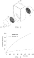
- FIG. 1 illustrates an embodiment of the isolation chip 10 according to the present disclosure.
- the isolation chip 10 includes a sample reservoir 11, a first chamber 16, a second chamber 18. The first chamber 16 and the second chamber 18 are disposed at opposite sides of the sample reservoir 11.
- the sample reservoir 11 includes a first side cover 111 and a second side cover 112 disposed at opposite sides of the sample reservoir 11.
- the first side cover 111 includes a first protruding block 12, which divides the first side cover 111 into a first cover portion 1111 and a second cover portion 1112 at opposite sides of the first protruding block 12.
- the second side cover 112 includes a second protruding block 13 facing the first protruding block 12.
- the second protruding block 13 divides the second side cover 112 into a third cover portion 1121 and a fourth cover portion 1122 at opposite sides of the second protruding block 13.
- the first cover portion 1111, the third cover portion 1121, the first protruding block 12, and the second protruding block 13 cooperatively define the sample reservoir 11.
- a sample inlet 113 is disposed on a top of the sample reservoir 11. A liquid sample can be injected or extracted out through the sample inlet 113.
- a chip base 14 is disposed at a bottom of the first side cover 111 and faces the first protruding block 12.
- a first filtration membrane 15 is disposed between the first protruding block 12 and the chip base 14.
- the first filtration membrane 15 faces the second cover portion 1112.
- the second cover portion 1112, the first filtration membrane 15, and the chip base 14 cooperatively define the first chamber 16.
- the first chamber 16 defines a first outlet 161, which connects the first chamber 16 to an ambient environment.
- Another chip base 14 is disposed at a bottom of the second side cover 112 and faces the second protruding block 13.
- a second filtration membrane 17 is disposed between the second protruding block 13 and the chip base 14.
- the second filtration membrane 17 faces the fourth cover portion 1122.
- the fourth cover portion 1122, the second filtration membrane 17, and the chip base 14 cooperatively define the second chamber 18.
- the second chamber 18 defines a second outlet 181, which connects the second chamber 18 to the ambient environment.
- a gap (not labeled in the drawings) is formed between the first protruding block 12 and the second protruding block 13, so that the liquid sample in the sample reservoir 11 can flow out of the sample reservoir 11, and then enter the first chamber 16 or the second chamber 18 through the first filtration membrane 15 or the second filtration membrane 17.
- a side of the first protruding block 12 facing the chip base 14 defines a first slot 121.
- the chip base 14 defines a second slot (not labeled) at a corresponding position.
- the first filtration membrane 15 is fixedly latched between the first slot 121 and the second slot.
- a side of the second protruding block 13 facing the chip base 14 defines a third slot 131.
- the chip base 14 defines a fourth slot (not labeled) at a corresponding position.
- the second filtration membrane 17 is fixedly latched between the third slot 131 and the fourth slot.
- the isolation chip 10 has a symmetrical structure. It should be noted that the isolation chip 10 may also be asymmetrical or any other structure that can perform the function of the present disclosure.
- the liquid sample is added to the sample reservoir 11.
- Each of the first outlet 161 and the second outlet 181 is connected to a vacuum system 30 (shown in FIG. 4 ).
- the vacuum system 30 When the vacuum system 30 generates a negative pressure in the first chamber 16 through the first outlet 161, compositions in the liquid sample that are smaller than the pores of the first filtration membrane 15 can enter the first chamber 16 through the first filtration membrane 15.
- the vacuum system 30 When the vacuum system 30 generates a negative pressure in the second chamber 18 through the second outlet 181, compositions in the liquid sample that are smaller than the pores of the second filtration membrane 17 can enter the second chamber 18 through the second filtration membrane 17.
- the vacuum system 30 includes two vacuum pumps, one connects to the first outlet 161 and the other one connects to the second outlet 181.
- the two vacuum pumps alternately provide negative pressure. Since negative pressure is alternately applied in the first chamber 16 and the second chamber 18, the compositions in the liquid sample can alternately flow through the first filtration membrane 15 and the second filtration membrane 17. Thus, target particles that are larger than the pores of the first filtration membrane 15 and the second filtration membrane 17 remain in the sample reservoir 11. Furthermore, some of the target particles that are absorbed on the first filtration membrane 15 and the second filtration membrane 17 can be flushed out under the negative pressure, thereby avoiding clogging of the first filtration membrane 15 and the second filtration membrane 17.
- the sample reservoir 11, the first filtration membrane 15, and the second filtration membrane 17 of the isolation chip 10 can mainly be made of plastic, glass, metal, or a composite material.
- the sample reservoir 11, the first filtration membrane 15, and the second filtration membrane 17 of the isolation chip 10 can mainly be made of polyethylene imine (PEI), polymethyl methacrylate (PMMA), or another transparent material.
- Processing methods of the isolation chip 10 include, but are not limited to, processing molding and injection molding.
- the first filtration membrane 15 and the second filtration membrane 17 may be made of a same material or different materials.
- the first filtration membrane 15 and the second filtration membrane 17 may have a same average pore size and/or a same pore size distribution, or may have different average pore sizes and/or different pore size distributions.
- the first filtration membrane 15 may be made of a single material or a combination of multiple materials.
- the first filtration membrane 15 and the second filtration membrane 17 may have porous materials, including but not limited to porous ceramic materials, porous plastic materials, and porous metal materials.
- each of the first filtration membrane 15 and the second filtration membrane 17 may be made of anodic aluminum oxide (AAO), polycarbonate, acetate fibers, polyethylene, polypropylene, polystyrene, and any combination thereof. More specifically, both the first filtration membrane 15 and the second filtration membrane 17 are made of anodic aluminum oxide that have a high porosity and an average pore size.
- AAO anodic aluminum oxide
- both the first filtration membrane 15 and the second filtration membrane 17 are made of anodic aluminum oxide that have a high porosity and an average pore size.
- the pore sizes of the first filtration membrane 15 and the second filtration membrane 17 can be varied according to the type of liquid samples and the type of target particles.
- the pore sizes of the first filtration membrane 15 and the second filtration membrane 17 are 20nm, which are slightly less than the sizes of exosomes (30 ⁇ 150 nm).
- exosomes can be isolated and purified from a cell culture sample that have passed a filtration membrane with a pore size of 200 nm.
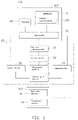
- FIG. 4 illustrates the isolation device 100 including a main module 101, an auxiliary module 102, and an interaction module 103.
- the main module 101 is configured to isolate and purify target particles from a number of liquid samples, thereby improving purify efficiency.
- the main module 101 includes a first support platform 1, a second support platform 2, a liquid provider 20, the vacuum system 30, a frequency converting module 40, and a liquid collector 50.
- FIG. 7 shows a working principle of a sampling module
- the first support platform 1 includes a number of the isolation chips 10 as described above.
- the number of the isolation chips 10 on the first support platform 1 is 12.
- the first support platform 1 can be rotated by a driver (such as a motor, not shown) about a first shaft 3, along a clockwise or counterclockwise direction for example, to rotate each isolation chip 10 on the first support platform 1, so that the isolation chips 10 are successively moved to a first preset position 5.
- the first preset position 5 is a sampling position.
- the isolation chips 10 are arranged on the first support platform 1 around the first shaft 3 of the first support platform 1. It is understood that the number of the isolation chips 10 on the first support platform 1 can be increased or decreased as required.
- the second support platform 2 comprises a plurality of containers 21.
- the number of the containers 21 is 12, which is the same as the number of the isolation chips 10.
- the second support platform 2 can be rotated about a second shaft 4 by a driver (such as a motor, not shown), along the clockwise or counterclockwise direction, to rotate each container 21 on the second support platform 2, so that the containers 21 are successively moved to a second preset position 6.
- the containers 21 are arranged on the second support platform 2 around the second shaft 4 of the second support platform 2.
- the liquid provider 20 includes a liquid sample pool 210, a first valve 220, and a washing liquid pool 230.
- the liquid sample pool 210 receives a same liquid sample or different liquid samples.
- the washing liquid pool 230 receives a washing liquid.
- the first valve 220 can control the liquid sample(s) in the liquid sample pool 210 and the washing liquid in the washing liquid pool 230 to be added to the containers 21.
- the liquid collector 50 includes at least one sampling member 510 that can be rotated about a third shaft 7 to form a sampling trajectory T.
- the first preset position 5 and the second preset position 6 are disposed on the sampling trajectory T.
- Each sampling member 510 is used to collect the liquid sample or the washing liquid in the container 21 at the second preset position 6, and to inject the collected liquid sample or washing liquid into the isolation chip 10 at the first preset position 5, so that the isolation chip 10 can isolate and wash the target particles.
- each sampling member 510 is a sampling needle, and two sampling needles are included.
- One sampling member 510 is on one side of a line connecting the first support platform 1 and the second support platform 2, and the other sampling member 510 is on the other side of the line connecting the first support platform 1 and the second support platform 2.
- Each sampling member 510 corresponds to one sampling trajectory T.
- Two first preset positions 5 and two second preset positions 6 are included.
- One of the first preset positions 5 and the corresponding second preset position 6 are located on the sampling trajectory T of one sampling member 510, and the other first preset position 5 and the corresponding second preset position 6 are located on the sampling trajectory T of the other sampling member 510.
- the two sampling members 510 can work simultaneously or independently.
- the liquid provider 20 may also include a driving component, such as a power pump or an air pump, to driving the liquid to flow.
- the vacuum system 30 alternately generates a negative pressure in the first chamber 16 and the second chamber 18 of each isolation chip 10 on the first support platform 1.
- the vacuum system 30 can include two independent vacuum units or a single vacuum system.
- the vacuum system 30 may also include equipment such as micro-vacuum pumps or micro-suction pumps. It is understood that the vacuum system 30 and each isolation chip 10 can be connected by an air-tight pipe.
- the vacuum system 30 includes a first vacuum pump 310 and a second vacuum pump 320.
- the isolation chips 10 are connected in parallel between the first vacuum pump 310 and the second vacuum pump 320. That is, the first vacuum pump 310 is connected to the first outlet 161 of each isolation chip 10.
- the second vacuum pump 320 is connected to the second outlet 181 of each isolation chip 10.
- the frequency converting module 40 is electrically connected to the vacuum system 30, and provides an electric power to the vacuum system 30, so that the negative pressure can be alternately generated in the first chamber 16 and the second chamber 18. Since the isolation chips 10 are connected in parallel, the negative pressure of the same intensity can be alternately generated in each isolation chip 10 at the same time. In other embodiments, when the number of the isolation chips 10 simultaneously working on the first support platform 1 is large (more than 6), the isolation chips 10 can be divided into two or more groups, which are connected to a number of the vacuum systems 30, so as to ensure stable negative pressure without attenuation.
- the frequency converting module 40 includes a frequency converter 410 and a second valve 420 connected to the frequency converter 410.
- the second valve 420 can be a liquid path converter, including but not limited to an electromagnetic valve or a rotary valve.
- the second valve 420 is alternately switched to connect one of the first vacuum pump 310 and the second vacuum pump 320, to cause the vacuum system 30 to alternately apply the negative pressure in the first chamber 16 and the second chamber 18. That is, when the second valve 420 connects to the first vacuum pump 310, the frequency converter 410 controls the first vacuum pump 310 to operate, which generate the negative pressure in each first chamber 16 by evacuating through each first outlet 161.
- the compositions in each sample reservoir 11 that are smaller than the pores of the corresponding first filtration membrane 15 can pass through the corresponding first filtration membrane 15 under the negative pressure and enter the corresponding first chamber 16.
- the back flow of the liquid sample in each sample reservoir 11 adjacent to the corresponding second filtration membrane 17 prevents any composition from accumulating in the pores of the corresponding second filtration membrane 17.
- the frequency converter 410 controls the first vacuum pump 310 to stop operating, and the second valve 420 is switched to connect to the second vacuum pump 320.
- the frequency converter 410 controls the second vacuum pump 320 to operate, which generates the negative pressure in each second chamber 18 by evacuating through each second outlet 181.
- the compositions in each sample reservoir 11 that are smaller than the pores of the corresponding second filtration membrane 17 can pass through the corresponding second filtration membrane 17 under the negative pressure and enter the corresponding second chamber 18.
- the back flow of the liquid sample in each sample reservoir 11 adjacent to the corresponding first filtration membrane 15 prevents any composition from accumulating in the pores of the corresponding first filtration membrane 15.
- the frequency converter 410 controls the second vacuum pump 320 to stop operating. The above-described procedures are repeated until complete isolation is achieved.
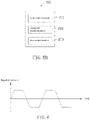
- the negative pressure alternating in each first chamber 16 and each second chamber 18 is caused by trapezoidal wave shaped pulse signals.
- the trapezoidal wave shaped pulse signals have an amplitude of -10 kpa to 80 kpa.
- the rectangular wave shaped pulse signals may also be replaced by a periodic sinusoidal or rectangular signal.
- a positive pressure can also be applied in one of the first chamber 16 or the second chamber 18 when applying the negative pressure in another one of the first chamber 16 or the second chamber 18, thereby reinforcing the back flow adjacent to the filtration membrane.
- the amplitude, the period, and the total time durations of the negative pressure can be varied according to the type of liquid samples, to obtain a best effect of back flow adjacent to the filtration membrane.
- RNA, DNA nucleic acid molecules
- lipoproteins lipoproteins
- lipids lipoproteins
- proteins peptide chains
- the main module 101 further includes a number of first liquid pools 330 and a number of second liquid pools 340.
- Each first liquid pool 330 is connected between the first vacuum pump 310 and the first outlet 161 of one corresponding isolation chip 10, and communicates with the first vacuum pump 310 and the first chamber 16 of the isolation chip 10.
- Each second liquid pool 340 is connected between the second vacuum pump 320 and the second outlet 181 of one corresponding isolation chip 10, and communicates with the second vacuum pump 320 and the second chamber 18 of the isolation chip 10. The first liquid pool 330 and the second liquid pool 340 prevent the liquid sample from flowing into the first vacuum pump 310 and the second vacuum pump 320.
- Each first liquid pool 330 or each second liquid pool 340 can be used as a safety bottle to prevent the liquid sample in the corresponding isolation chip 10 from flowing into the vacuum pump, or used as a waste liquid bottle to collect liquid or washing liquid remaining in each isolation chip 10 after the isolation.
- the auxiliary module 102 can ensure that the isolation device 100 operates normally and efficiently.
- the auxiliary module 102 includes a detector 60 and a controller 70.
- the detector 60 detects a liquid level of the liquid sample in the sample reservoir 11.
- the controller 70 is electrically connected to the detector 60 and the frequency converting module 40.
- the controller 70 obtains the detected liquid level, and determines whether the liquid sample or the washing liquid needs to be further added or whether the isolation of the liquid sample is finished according to the obtained liquid level and a preset amount of the liquid sample.
- the controller 70 controls the frequency converting module 40 to stop generating the negative pressure in the first chamber 16 and the second chamber 18.
- the controller 70 can be a collection of logical relationships embedded in hardware or firmware, or a series of programs written in a programming language and stored in memory or other firmware.
- the controller 70 controls the frequency converting module 40 to generate the negative pressure in the first chamber 16 and the second chamber 18 according to preset pressure data.
- the interaction module 103 allows the target particles isolation from the liquid sample to meet actual need, so that the isolation device 100 is maneuverable.
- the interaction module 103 includes an interaction interface 80 for a user to input data related to the isolation processes through an input unit (for example, a touch panel, a keyboard, or a mouse) of the isolation device 100. That is, the user can preset the data related to the isolation processes through the interaction interface 80.
- the data related to the isolation processes includes the preset amount of the liquid sample, the preset amount of the washing liquid, and the preset pressure data.
- the preset pressure data includes the amplitude, the period, and the total time durations of the negative pressure.
- the controller 70 is further electrically connected to the interaction interface 80. Thus, the controller 70 can obtain the input data from the interaction interface 80, and control the frequency converting module 40 or the liquid provider 20 to operate accordingly.
- the interaction module 103 can further include a transmission interface 81 configured to connect the isolation device 100 to a peripheral device (for example, a smart phone or a USB flash disk).
- the isolation device 100 can transmit data related to the isolation processes to the peripheral device through the transmission interface 81.
- the transmission interface 81 can be a USB interface or a wireless interface.
- the isolation device 100 provided by the present disclosure can automatically isolate target particles from a liquid sample, thereby obtaining components in the sample reservoir 11 that cannot pass through a filtration membrane. At the same time, a direction of liquid flow in the sample reservoir 11 is changed by the change of negative pressure in chambers on both sides of the sample reservoir 11, which can reduce the amounts of components that adhering to the filtration membrane. Clogging of the filtration membrane in the isolation process can be avoided.
- the isolation device 100 is of low cost and easy to use, which reduces the workload of experimenters.
- An embodiment of an isolation control system 200 is further provided according to the present disclosure, which can be applied in the isolation device 100.
- the auxiliary module 102 of the isolation device 100 further includes a memory 71.
- the isolation control system 200 is stored in the memory 71.
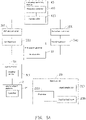
- the isolation control system 200 includes a number of modules, which are a collection of software instructions executable by the controller 70 to perform the function of the isolation control system 200. Referring to FIGS. 4 and 5B , the isolation control system 200 includes a liquid path machinery module 202 and a main control module 203.
- the liquid path machinery module 202 controls each sampling member 510 to provide the liquid sample and the washing liquid into the sample reservoir 11 of each isolation chip 10.
- the main control module 203 controls the vacuum system 30 alternately generates the negative pressure in the first chamber 16 and the second chamber 18 of each isolation chip 10 through the frequency converting module 40.
- the vacuum system 30 includes the first vacuum pump 310 and the second vacuum pump 320.
- the first vacuum pump 310 is connected to the first outlet 161 of each isolation chip 10.
- the second vacuum pump 320 is connected to the second outlet 181 of each isolation chip 10.
- the frequency converting module 40 includes the frequency converter 410 and the second valve 420 connected to the frequency converter 410.
- the main control module 203 controls the second valve 420 to connect to the first vacuum pump 310, so that the frequency converter 410 controls the first vacuum pump 310 to operate, which evacuates through each first outlet 161 to generate the negative pressure in the corresponding first chamber 16.
- the main control module 203 further controls the second valve 420 to connect to the second vacuum pump 320, so that the frequency converter 410 controls the second vacuum pump 320 to operate, which evacuates through each second outlet 181 to generate the negative pressure in the corresponding
- the isolation device 100 further includes the detector 60.
- the detector 60 detects a liquid level of the liquid sample in the sample reservoir 11.
- the isolation control system 200 further includes a drive control module 201.
- the drive control module 201 obtains the detected liquid level, and determines whether the isolation of the liquid sample is finished according to the obtained liquid level and the preset amount of the liquid sample.
- the drive control module 201 sends a stop command to the main control module 203.
- the main control module 203 responds to the stop command, and controls the frequency converting module 40 to stop operating, so as to stop generating the negative pressure in the first chamber 16 and the second chamber 18 of the corresponding isolation chip 10.
- the drive control module 201 further obtains the preset pressure data, and sends a control command including the preset pressure data to the main control module 203.
- the main control module 203 responds to the control command, and controls the frequency converting module 40 to generate the negative pressure in each first chamber 16 and each second chamber 18 according to the preset pressure data.
- the drive control module 201 further obtains the preset amount of each liquid sample, and sends a second control command including the preset amount of each liquid sample to the liquid path machinery module 202.
- the liquid path machinery module 202 responds to the second control command, and controls a working duration of each sampling member 510 according to the preset amount of each liquid sample, thereby allowing the liquid sample with the preset amount to be added to the corresponding sample reservoir 11.
- the drive control module 201 further obtains the preset amount of the washing liquid, and sends a third control command including the preset amount of the washing liquid to the liquid path machinery module 202.
- the liquid path machinery module 202 responds to the third control command, and controls a working duration of each sampling member 510 according to the preset amount of the washing liquid, thereby allowing the washing liquid with the preset amount to be added to the corresponding sample reservoir 11
- An embodiment of an isolation method for isolating target particles from liquid samples is further provided according to the present disclosure.
- the method includes the following steps.
- the isolation chips 10 are placed on the first support platform 1, and liquid samples are placed on the second support platform 2.
- the second support platform 2 is rotated, so that the liquid samples can be moved to the second preset position 6 successively.
- the first support platform 1 is rotated, so that the isolation chips 10 can be moved to the first preset position 5 successively.
- the sampling member 510 is controlled to be rotated to form the sampling trajectory T, and the first preset position 5 and the second preset position 6 are in the sampling trajectory T.
- the sampling member 510 collects the liquid sample at the second preset position 6, and injects the collected liquid sample into the isolation chip 10 at the first preset position 5.
- the first chamber 16 of each isolation chip 10 is evacuated through the corresponding first outlet 161 to generate the negative pressure in the first chamber 16.
- the first outlet 161 and the second outlet 181 of each isolation chip 10 are connected to the vacuum system 30 before evacuating the first chamber 16, the first outlet 161 and the second outlet 181 of each isolation chip 10 are connected to the vacuum system 30. Then, the vacuum system 30 evacuates each first chamber 16 through the corresponding first outlet 161, to generate the negative pressure in each first chamber 16.
- the vacuum system 30 evacuates each first chamber 16 through the corresponding first outlet 161, to generate the negative pressure in each first chamber 16.
- compositions in each sample reservoir 11 having sizes which are smaller than sizes of the pores of the first filtration membrane 15 can enter the corresponding first chamber 16 through the corresponding first filtration membrane 15.
- the compositions having sizes which are smaller than the sizes of the pores of the first filtration membrane 15 can also enter the first liquid pool 330 through the first outlet 161.
- the sample inlet 113 can be closed before evacuating.
- the sample inlet 113 can be closed.
- a flowing speed of the liquid sample in each sample reservoir 11 between the first filtration membrane 15 and the second filtration membrane 17 can be accelerated, so that the back flow adjacent to the first filtration membrane 15 and the second filtration membrane 17 can be accelerated to avoid clogging of the filtration membranes.
- a positive pressure can also be generated in each second chamber 18 to further avoid clogging of the filtration membranes.
- the second chamber 18 of each isolation chip 10 is evacuated through the corresponding second outlet 181 to generate the negative pressure in the second chamber 18.
- compositions which are absorbed on the first filtration membrane 15 may be returned to the corresponding sample reservoir 11 with the flow of air and/or liquid. Furthermore, the compositions in each sample reservoir 11 having sizes which are smaller than the sizes of the pores of the corresponding second filtration membrane 17 can enter the corresponding second chamber 18 through the corresponding second filtration membrane 17. In some cases, when the second chamber 18 has a small volume or when the negative pressure is switched to fast, the compositions having sizes which are smaller than the sizes of the pores of the corresponding second filtration membrane 17 can also enter the second liquid pool 340 through the second outlet 181. Steps 4 and 5 can also be performed simultaneously.
- a positive pressure can be generated in each first chamber 16 to further avoid blocking and clogging of the filtration membrane.
- the steps 5 to 8 can be repeated for a number of times to further remove the compositions in each liquid sample that having sizes which are smaller than the sizes of the pores of the corresponding filtration membranes, and causing the target particles having sizes which are larger than the sizes of the pores of the corresponding filtration membrane to remain in the corresponding sample reservoir 11.
- the method can further include the following step.
- step 9 the washing liquid is added to the sample reservoir 11 of each isolation chip 10. Then, the step 5 to 8 can be repeated for a number of times to wash each isolation chip 10.
- isolation device 100 Using the above-described isolation device 100 to isolate and purify exosomes from a cell culture sample of 20 mL, a high yield of exosomes is obtained within 30 min.
- the isolation device 100 can efficiently obtain purified exosomes from a biological sample of large volume.
- the advantages of the isolation device 100 include the followings of: 1) high throughput (processing multiple liquid samples, such as 2 to 100 samples, in parallel); 2) automatic processing; 3) simple and standardized operation; 4) high yield and purity; 5) free of mark; 6) cost-effective; 7) high stability and repeatability; 8) handle a variety of different biological samples, including plasma, urine, brain and marrow fluid, saliva, tears, latex, cell culture liquid, etc.
Landscapes
- Health & Medical Sciences (AREA)
- Chemical & Material Sciences (AREA)
- Life Sciences & Earth Sciences (AREA)
- Engineering & Computer Science (AREA)
- Analytical Chemistry (AREA)
- General Health & Medical Sciences (AREA)
- Biochemistry (AREA)
- Organic Chemistry (AREA)
- Zoology (AREA)
- Wood Science & Technology (AREA)
- Bioinformatics & Cheminformatics (AREA)
- Physics & Mathematics (AREA)
- Immunology (AREA)
- General Physics & Mathematics (AREA)
- Pathology (AREA)
- Biomedical Technology (AREA)
- Biotechnology (AREA)
- Molecular Biology (AREA)
- Microbiology (AREA)
- Sustainable Development (AREA)
- General Engineering & Computer Science (AREA)
- Genetics & Genomics (AREA)
- Computer Hardware Design (AREA)
- Cell Biology (AREA)
- Chemical Kinetics & Catalysis (AREA)
- Hematology (AREA)
- Clinical Laboratory Science (AREA)
- Sampling And Sample Adjustment (AREA)
- Apparatus Associated With Microorganisms And Enzymes (AREA)
- Investigating Or Analysing Biological Materials (AREA)
Applications Claiming Priority (1)
| Application Number | Priority Date | Filing Date | Title |
|---|---|---|---|
| PCT/CN2019/096425 WO2021007825A1 (zh) | 2019-07-17 | 2019-07-17 | 分离装置及分离液体样本中目标颗粒的方法 |
Publications (4)
| Publication Number | Publication Date |
|---|---|
| EP4001914A1 true EP4001914A1 (de) | 2022-05-25 |
| EP4001914A4 EP4001914A4 (de) | 2023-05-24 |
| EP4001914C0 EP4001914C0 (de) | 2025-04-09 |
| EP4001914B1 EP4001914B1 (de) | 2025-04-09 |
Family
ID=74209642
Family Applications (1)
| Application Number | Title | Priority Date | Filing Date |
|---|---|---|---|
| EP19937743.3A Active EP4001914B1 (de) | 2019-07-17 | 2019-07-17 | Trennvorrichtung und verfahren zur trennung von zielpartikeln in flüssigen proben |
Country Status (6)
| Country | Link |
|---|---|
| US (2) | US11874209B2 (de) |
| EP (1) | EP4001914B1 (de) |
| JP (1) | JP7312507B2 (de) |
| KR (1) | KR102708545B1 (de) |
| CN (1) | CN112601959A (de) |
| WO (1) | WO2021007825A1 (de) |
Families Citing this family (7)
| Publication number | Priority date | Publication date | Assignee | Title |
|---|---|---|---|---|
| CN114377549B (zh) * | 2022-01-18 | 2023-04-11 | 深圳汇芯生物医疗科技有限公司 | 自动化分离设备及分离液体样本中目标颗粒的方法 |
| CN116555025A (zh) * | 2022-01-27 | 2023-08-08 | 上海思路迪生物医学科技有限公司 | 用于血浆中外泌体捕获和核酸提取的微流控芯片及方法 |
| CN116272387A (zh) * | 2023-04-28 | 2023-06-23 | 深圳汇芯生物医疗科技有限公司 | 超声洗脱结构及分离装置 |
| CN119374994B (zh) * | 2024-12-27 | 2025-03-28 | 杭州达析生物科技有限公司 | 一种滤膜与磁珠相结合的全血分离血浆装置及方法 |
| CN120176955B (zh) * | 2025-05-21 | 2025-08-01 | 南京翔瑞智能装备技术股份有限公司 | 一种旋转阀测试装置 |
| CN120685416B (zh) * | 2025-07-07 | 2026-03-13 | 山东省海洋资源与环境研究院(山东省海洋环境监测中心、山东省水产品质量检验中心) | 一种近岸海洋环境监测的抽滤筒、抽滤装置及抽滤方法 |
| CN120820397A (zh) * | 2025-09-09 | 2025-10-21 | 深圳汇芯生物医疗科技有限公司 | 一种液体样本中目标颗粒分离调控方法及装置 |
Family Cites Families (7)
| Publication number | Priority date | Publication date | Assignee | Title |
|---|---|---|---|---|
| JP4221349B2 (ja) * | 2004-09-17 | 2009-02-12 | 株式会社日立ハイテクノロジーズ | 自動分析装置 |
| CN1963527B (zh) * | 2005-11-10 | 2011-12-14 | 深圳迈瑞生物医疗电子股份有限公司 | 全自动生化分析仪及其分析方法 |
| US10596522B2 (en) * | 2015-04-24 | 2020-03-24 | The Regents Of The University Of California | Hemolysis-free blood plasma separation |
| CN108126522B (zh) * | 2017-12-21 | 2020-08-18 | 深圳汇芯生物医疗科技有限公司 | 分离芯片、分离装置及分离液体样本中目标颗粒的方法 |
| US10758867B2 (en) * | 2017-11-30 | 2020-09-01 | Wellsim Biomedical Technologies, Inc | Isolation device and isolation method |
| CN109439525B (zh) * | 2017-11-30 | 2023-07-07 | 深圳汇芯生物医疗科技有限公司 | 分离芯片及该分离芯片的制作方法 |
| CN208297542U (zh) * | 2018-06-05 | 2018-12-28 | 深圳天辰医疗科技有限公司 | Poct全自动化学发光免疫分析仪 |
-
2019
- 2019-07-17 KR KR1020227005184A patent/KR102708545B1/ko active Active
- 2019-07-17 JP JP2022503474A patent/JP7312507B2/ja active Active
- 2019-07-17 EP EP19937743.3A patent/EP4001914B1/de active Active
- 2019-07-17 WO PCT/CN2019/096425 patent/WO2021007825A1/zh not_active Ceased
- 2019-07-17 CN CN201980002362.5A patent/CN112601959A/zh active Pending
-
2022
- 2022-01-14 US US17/576,654 patent/US11874209B2/en active Active
-
2023
- 2023-12-06 US US18/530,661 patent/US12253447B2/en active Active
Also Published As
| Publication number | Publication date |
|---|---|
| US20240102900A1 (en) | 2024-03-28 |
| EP4001914C0 (de) | 2025-04-09 |
| WO2021007825A1 (zh) | 2021-01-21 |
| US20220136938A1 (en) | 2022-05-05 |
| CN112601959A (zh) | 2021-04-02 |
| US11874209B2 (en) | 2024-01-16 |
| EP4001914A4 (de) | 2023-05-24 |
| EP4001914B1 (de) | 2025-04-09 |
| KR102708545B1 (ko) | 2024-09-24 |
| JP7312507B2 (ja) | 2023-07-21 |
| JP2022541279A (ja) | 2022-09-22 |
| US12253447B2 (en) | 2025-03-18 |
| KR20220027262A (ko) | 2022-03-07 |
Similar Documents
| Publication | Publication Date | Title |
|---|---|---|
| US12253447B2 (en) | Isolation method for isolating target particles from liquid samples | |
| CN103018224B (zh) | 基于离心微流控技术的稀少细胞分离检测系统及方法 | |
| TWI624294B (zh) | 用於樣本處理之方法及裝置 | |
| KR101533230B1 (ko) | 다단 미세유체 칩 및 이를 이용한 시료의 선택적 분리방법 | |
| CN109439525B (zh) | 分离芯片及该分离芯片的制作方法 | |
| CN104762193A (zh) | 核酸自动提取微流控装置 | |
| TW201329231A (zh) | 用於自脂肪組織分離非脂肪細胞之方法及裝置 | |
| CN105647799B (zh) | 一种组合式场流分离的循环肿瘤细胞分离装置 | |
| CN107400623B (zh) | 循环肿瘤细胞自动捕获微流控芯片及其自动捕获方法 | |
| CN105296327A (zh) | 一种核酸提取装置及其提取方法 | |
| CN110079457A (zh) | 微流控芯片及外泌体提取方法 | |
| US12071611B2 (en) | Rare cell capture system and application thereof | |
| CN211771270U (zh) | 一种用于外周血液中外泌体分离、富集的微流控芯片 | |
| CN117417819A (zh) | 一种集成全封闭式核酸检测系统以及检测装置 | |
| CN110004062A (zh) | 分选富集数量极稀少循环肿瘤细胞的装置和方法 | |
| CN113444630A (zh) | 一种多孔滤膜微流控芯片过滤分离循环肿瘤细胞的自动化控制系统 | |
| CN205898536U (zh) | 一种分离提取外泌体的叠层离心过滤装置 | |
| CN115228521B (zh) | 生物粒子分离装置以及微流控芯片 | |
| CN209485831U (zh) | 医院用的尿液细胞外囊泡富集装置 | |
| CN210193892U (zh) | 微流控芯片 | |
| CN118103140A (zh) | 分离不同分析物类的分析物 | |
| CN114292742A (zh) | 基于数字微流控的集成化外泌体来源核酸提取系统及方法 | |
| CN206570309U (zh) | 一种循环肿瘤细胞分选富集装置 | |
| CN214764552U (zh) | 分离芯片组件 | |
| CN210356708U (zh) | 一种血液过滤装置 |
Legal Events
| Date | Code | Title | Description |
|---|---|---|---|
| STAA | Information on the status of an ep patent application or granted ep patent |
Free format text: STATUS: THE INTERNATIONAL PUBLICATION HAS BEEN MADE |
|
| PUAI | Public reference made under article 153(3) epc to a published international application that has entered the european phase |
Free format text: ORIGINAL CODE: 0009012 |
|
| STAA | Information on the status of an ep patent application or granted ep patent |
Free format text: STATUS: REQUEST FOR EXAMINATION WAS MADE |
|
| 17P | Request for examination filed |
Effective date: 20220128 |
|
| AK | Designated contracting states |
Kind code of ref document: A1 Designated state(s): AL AT BE BG CH CY CZ DE DK EE ES FI FR GB GR HR HU IE IS IT LI LT LU LV MC MK MT NL NO PL PT RO RS SE SI SK SM TR |
|
| DAV | Request for validation of the european patent (deleted) | ||
| DAX | Request for extension of the european patent (deleted) | ||
| A4 | Supplementary search report drawn up and despatched |
Effective date: 20230424 |
|
| RIC1 | Information provided on ipc code assigned before grant |
Ipc: G01N 35/00 20060101ALI20230418BHEP Ipc: C12M 1/36 20060101ALI20230418BHEP Ipc: G01N 33/48 20060101AFI20230418BHEP |
|
| GRAP | Despatch of communication of intention to grant a patent |
Free format text: ORIGINAL CODE: EPIDOSNIGR1 |
|
| STAA | Information on the status of an ep patent application or granted ep patent |
Free format text: STATUS: GRANT OF PATENT IS INTENDED |
|
| INTG | Intention to grant announced |
Effective date: 20241217 |
|
| GRAS | Grant fee paid |
Free format text: ORIGINAL CODE: EPIDOSNIGR3 |
|
| GRAA | (expected) grant |
Free format text: ORIGINAL CODE: 0009210 |
|
| STAA | Information on the status of an ep patent application or granted ep patent |
Free format text: STATUS: THE PATENT HAS BEEN GRANTED |
|
| AK | Designated contracting states |
Kind code of ref document: B1 Designated state(s): AL AT BE BG CH CY CZ DE DK EE ES FI FR GB GR HR HU IE IS IT LI LT LU LV MC MK MT NL NO PL PT RO RS SE SI SK SM TR |
|
| REG | Reference to a national code |
Ref country code: GB Ref legal event code: FG4D |
|
| REG | Reference to a national code |
Ref country code: CH Ref legal event code: EP |
|
| REG | Reference to a national code |
Ref country code: DE Ref legal event code: R096 Ref document number: 602019068587 Country of ref document: DE |
|
| REG | Reference to a national code |
Ref country code: IE Ref legal event code: FG4D |
|
| U01 | Request for unitary effect filed |
Effective date: 20250417 |
|
| U07 | Unitary effect registered |
Designated state(s): AT BE BG DE DK EE FI FR IT LT LU LV MT NL PT RO SE SI Effective date: 20250425 |
|
| U20 | Renewal fee for the european patent with unitary effect paid |
Year of fee payment: 7 Effective date: 20250723 |
|
| PG25 | Lapsed in a contracting state [announced via postgrant information from national office to epo] |
Ref country code: ES Free format text: LAPSE BECAUSE OF FAILURE TO SUBMIT A TRANSLATION OF THE DESCRIPTION OR TO PAY THE FEE WITHIN THE PRESCRIBED TIME-LIMIT Effective date: 20250409 |
|
| PG25 | Lapsed in a contracting state [announced via postgrant information from national office to epo] |
Ref country code: GR Free format text: LAPSE BECAUSE OF FAILURE TO SUBMIT A TRANSLATION OF THE DESCRIPTION OR TO PAY THE FEE WITHIN THE PRESCRIBED TIME-LIMIT Effective date: 20250710 |
|
| PGFP | Annual fee paid to national office [announced via postgrant information from national office to epo] |
Ref country code: NO Payment date: 20250728 Year of fee payment: 7 |
|
| PG25 | Lapsed in a contracting state [announced via postgrant information from national office to epo] |
Ref country code: PL Free format text: LAPSE BECAUSE OF FAILURE TO SUBMIT A TRANSLATION OF THE DESCRIPTION OR TO PAY THE FEE WITHIN THE PRESCRIBED TIME-LIMIT Effective date: 20250409 |
|
| PGFP | Annual fee paid to national office [announced via postgrant information from national office to epo] |
Ref country code: GB Payment date: 20250826 Year of fee payment: 7 |
|
| PG25 | Lapsed in a contracting state [announced via postgrant information from national office to epo] |
Ref country code: HR Free format text: LAPSE BECAUSE OF FAILURE TO SUBMIT A TRANSLATION OF THE DESCRIPTION OR TO PAY THE FEE WITHIN THE PRESCRIBED TIME-LIMIT Effective date: 20250409 |
|
| PGFP | Annual fee paid to national office [announced via postgrant information from national office to epo] |
Ref country code: CH Payment date: 20250826 Year of fee payment: 7 |
|
| PG25 | Lapsed in a contracting state [announced via postgrant information from national office to epo] |
Ref country code: RS Free format text: LAPSE BECAUSE OF FAILURE TO SUBMIT A TRANSLATION OF THE DESCRIPTION OR TO PAY THE FEE WITHIN THE PRESCRIBED TIME-LIMIT Effective date: 20250709 |
|
| PG25 | Lapsed in a contracting state [announced via postgrant information from national office to epo] |
Ref country code: IS Free format text: LAPSE BECAUSE OF FAILURE TO SUBMIT A TRANSLATION OF THE DESCRIPTION OR TO PAY THE FEE WITHIN THE PRESCRIBED TIME-LIMIT Effective date: 20250809 |
|
| PG25 | Lapsed in a contracting state [announced via postgrant information from national office to epo] |
Ref country code: SM Free format text: LAPSE BECAUSE OF FAILURE TO SUBMIT A TRANSLATION OF THE DESCRIPTION OR TO PAY THE FEE WITHIN THE PRESCRIBED TIME-LIMIT Effective date: 20250409 |
|
| PG25 | Lapsed in a contracting state [announced via postgrant information from national office to epo] |
Ref country code: CZ Free format text: LAPSE BECAUSE OF FAILURE TO SUBMIT A TRANSLATION OF THE DESCRIPTION OR TO PAY THE FEE WITHIN THE PRESCRIBED TIME-LIMIT Effective date: 20250409 |
|
| PG25 | Lapsed in a contracting state [announced via postgrant information from national office to epo] |
Ref country code: SK Free format text: LAPSE BECAUSE OF FAILURE TO SUBMIT A TRANSLATION OF THE DESCRIPTION OR TO PAY THE FEE WITHIN THE PRESCRIBED TIME-LIMIT Effective date: 20250409 |
|
| PLBE | No opposition filed within time limit |
Free format text: ORIGINAL CODE: 0009261 |
|
| STAA | Information on the status of an ep patent application or granted ep patent |
Free format text: STATUS: NO OPPOSITION FILED WITHIN TIME LIMIT |
|
| REG | Reference to a national code |
Ref country code: CH Ref legal event code: L10 Free format text: ST27 STATUS EVENT CODE: U-0-0-L10-L00 (AS PROVIDED BY THE NATIONAL OFFICE) Effective date: 20260218 |
|
| 26N | No opposition filed |
Effective date: 20260112 |