EP4001928B1 - Bouchon d'isolation à capteur - Google Patents
Bouchon d'isolation à capteur Download PDFInfo
- Publication number
- EP4001928B1 EP4001928B1 EP20208737.5A EP20208737A EP4001928B1 EP 4001928 B1 EP4001928 B1 EP 4001928B1 EP 20208737 A EP20208737 A EP 20208737A EP 4001928 B1 EP4001928 B1 EP 4001928B1
- Authority
- EP
- European Patent Office
- Prior art keywords
- voltage
- mesh
- insulating material
- sensored
- electrode
- Prior art date
- Legal status (The legal status is an assumption and is not a legal conclusion. Google has not performed a legal analysis and makes no representation as to the accuracy of the status listed.)
- Active
Links
Images


Classifications
-
- G—PHYSICS
- G01—MEASURING; TESTING
- G01R—MEASURING ELECTRIC VARIABLES; MEASURING MAGNETIC VARIABLES
- G01R15/00—Details of measuring arrangements of the types provided for in groups G01R17/00 - G01R29/00, G01R33/00 - G01R33/26 or G01R35/00
- G01R15/04—Voltage dividers
- G01R15/06—Voltage dividers having reactive components, e.g. capacitive transformer
-
- G—PHYSICS
- G01—MEASURING; TESTING
- G01R—MEASURING ELECTRIC VARIABLES; MEASURING MAGNETIC VARIABLES
- G01R15/00—Details of measuring arrangements of the types provided for in groups G01R17/00 - G01R29/00, G01R33/00 - G01R33/26 or G01R35/00
- G01R15/14—Adaptations providing voltage or current isolation, e.g. for high-voltage or high-current networks
- G01R15/16—Adaptations providing voltage or current isolation, e.g. for high-voltage or high-current networks using capacitive devices
-
- H—ELECTRICITY
- H01—ELECTRIC ELEMENTS
- H01B—CABLES; CONDUCTORS; INSULATORS; SELECTION OF MATERIALS FOR THEIR CONDUCTIVE, INSULATING OR DIELECTRIC PROPERTIES
- H01B17/00—Insulators or insulating bodies characterised by their form
- H01B17/26—Lead-in insulators; Lead-through insulators
- H01B17/28—Capacitor type
-
- H—ELECTRICITY
- H01—ELECTRIC ELEMENTS
- H01B—CABLES; CONDUCTORS; INSULATORS; SELECTION OF MATERIALS FOR THEIR CONDUCTIVE, INSULATING OR DIELECTRIC PROPERTIES
- H01B17/00—Insulators or insulating bodies characterised by their form
- H01B17/56—Insulating bodies
-
- H—ELECTRICITY
- H01—ELECTRIC ELEMENTS
- H01B—CABLES; CONDUCTORS; INSULATORS; SELECTION OF MATERIALS FOR THEIR CONDUCTIVE, INSULATING OR DIELECTRIC PROPERTIES
- H01B3/00—Insulators or insulating bodies characterised by the insulating materials; Selection of materials for their insulating or dielectric properties
- H01B3/18—Insulators or insulating bodies characterised by the insulating materials; Selection of materials for their insulating or dielectric properties mainly consisting of organic substances
- H01B3/30—Insulators or insulating bodies characterised by the insulating materials; Selection of materials for their insulating or dielectric properties mainly consisting of organic substances plastics; resins; waxes
- H01B3/40—Insulators or insulating bodies characterised by the insulating materials; Selection of materials for their insulating or dielectric properties mainly consisting of organic substances plastics; resins; waxes epoxy resins
Definitions
- WO 2019/186607 A1 addresses such problems. It proposes a capacitive voltage sensor comprising an electrode comprising a plurality of first elements having an elongated shape, arranged circumferentially side by side to form a tubular body and cantilevered with their distal ends joined to each other and their proximal ends free.
- United States patent 3,513,253 mentions a condenser type bushing assembly having a body portion formed of a cast solid insulation system, a conductor stud, and one or more capacitor plates formed of tubular members embedded in the cast body portion. The tubular members each have a wall formed of electrical insulating strands of filaments, which are bonded together to form an open mesh.
- EP 0889487 A2 refers to a bushing insulator having a metal insert for shielding an electrical field. Such inserts are described to be normally made using a metal mesh that must be able to withstand the mechanical stresses that occur during the phase for moulding the insulating material to avoid deformations that could impact its correct positioning.
- German patent application publication DE 19547120 A1 describes an electrode which is made from wire mesh, and which has a curved surface with edge zones rounded off in the radial direction.
- US 2016/0245845 A1 refers to a capacitive sensor in which a tubular shielding body is formed by a mantle having a plurality of first through openings.
- a sensored insulation plug for being inserted into a rear cavity of a medium-voltage or high-voltage separable connector in a power distribution network of a national grid, and operable to insulate a connection element of the separable connector on an elevated voltage and to sense the elevated voltage.
- the sensored insulation plug comprises
- portions of the mesh can better follow any movement of the insulating material on a small scale. Because of the mesh being deformable, one portion of the mesh can follow a movement of the insulating material in its vicinity, while another portion of the mesh can follow a movement of the insulating material in its own vicinity.
- the deformability thereby allows portions of the mesh to follow movement of the insulating material in their respective vicinities independently from each other, or at least with less dependence from each other. Deformability thus ensures that portions of the mesh can follow local movement of the insulating material, as opposed to the entire mesh or the entire sensing electrode.
- the present disclosure relates to voltage sensing devices for use in medium-voltage or high-voltage power distribution networks in which electrical power is distributed via HV/MV power cables, transformers, switchgears, substations etc. with currents of tens or hundreds of amperes and voltages of tens of kilovolts.
- the term "medium voltage” or “MV” as used herein refers to AC voltages in the range of 1 kilovolt (kV) to 72 kV, whereas the term “high voltage” or “HV” refers to AC voltages of more than 72 kV.
- Medium voltage and high voltage are collectively referred to herein as "elevated voltage”.
- a separable connector as referred to herein usually has a front cavity to receive a protruding portion of a bushing of the switchgear or the transformer, and an opposed rear cavity facilitating access to a connection element, such as a cable lug, on elevated voltage inside the separable connector.
- the connection element is conductive and is electrically and mechanically connected to the power conductor of the power cable.
- the connection element can be connected mechanically and electrically, e.g. by a conductive threaded stud, to a conductive element of the bushing, so that power can flow from the power cable through the connection element, the stud and the bushing into the switchgear or transformer.
- the connection element is on the elevated voltage of the power conductor of the cable.
- the rear cavity of a separable connector can receive a matching insulation plug to insulate the connection element and to fill the space of the rear cavity to reduce the risk of electrical discharges.
- Such matching pairs of separable connector and insulation plug are commercially available at moderate cost.
- the mechanical interface between a separable connector and an insulation plug is governed by de-facto standards. Many of such interfaces conform to an existing standard for bushings, some form a Type C interface as described in the German standards DIN EN 50180 for bushings and DIN EN 50181 for plug-in type bushings, others conform to ANSI/IEEE standard 386.
- bodies of insulation plugs are slightly larger than the rear cavity, so that after the plug is urged into the rear cavity with some force, the surfaces of plug and cavity are in an intimate surface contact, thus reducing the risk of electrical discharges.
- the body of a sensored insulation plug according to the present disclosure is shaped for mating with a rear cavity of a separable connector in the same way as the body of a non-sensored insulation plug.
- the body of the sensored insulation plug may, for example, have a frustoconical shape for being inserted into a corresponding frustoconical recess of corresponding shape (the rear cavity) at a rear side of the separable connector, thereby mating the sensored insulation plug with the separable connector.
- connection element of a separable connector is electrically connected to the conductor of the power cable terminated by the separable connector and is on elevated voltage when the cable is in use.
- connection element such as a cable lug
- the protruding portion of the connection element usually has an aperture or a thread for attachment to a stud or screw which connects the connection element electrically and mechanically, e.g. with a conductor of a bushing.
- connection element serves to electrically and mechanically connect the power cable and the separable connector, e.g. to a bushing.
- the high-voltage electrode of the primary capacitor of the sensored insulation plug as described herein is - when in use - directly electrically connected to the connection element, so that a voltage sensor based on a voltage divider comprising the primary capacitor in its high-voltage portion can sense the elevated voltage of the connection element and thereby the elevated voltage of the power cable conductor, before and after connection of the power cable to the bushing.
- the primary capacitor is operable as a high-voltage capacitor in a voltage divider for sensing the elevated voltage.
- the connection element is electrically connected to the voltage divider such that the voltage divider is usable to sense the elevated voltage of the connection element.
- the connection element on elevated voltage is electrically connected to the high-voltage electrode of the primary capacitor in the sensored insulation plug which in turn is operable as a high-voltage capacitor in a voltage divider for sensing the elevated voltage.
- the high-voltage electrode of the primary capacitor may be not only electrically, but also mechanically connected to the connection element.
- This mechanical connection advantageously is an electrically conductive connection.
- the mechanical connection may be a direct mechanical connection, i.e. a portion of the high-voltage electrode is mechanically connected to the connection element without any intermediate element.
- a contact piece of the sensored insulation plug according to the present disclosure may be the high-voltage-electrode, or it may comprise the high-voltage electrode. Where the contact piece comprises the high-voltage electrode, the contact piece may have an engagement portion to engage with an intermediate element connecting the contact piece electrically with the connection element of the separable connector, and an electrode portion forming the high-voltage electrode.
- the engagement portion and the electrode portion may be formed as a single piece, e.g. as a single piece of metal. Alternatively, they may be formed as separate elements.
- the plug axis defines axial directions, which are directions parallel to the plug axis, and radial directions, which are directions orthogonal to the axial directions.
- the insulating material is liquid during the manufacturing of the plug body and solidifies thereafter to form a rigid plug body. Solidification may be obtained by curing, hardening, crosslinking, or in other known manners.
- the insulating material may be, for example, a solidifiable, e.g. a hardenable or curable, liquid epoxy resin or a solidifiable, e.g. hardenable or curable, liquid mixture of an epoxy resin with other materials, such as fillers, or a solidifiable, e.g. hardenable or curable, polyurethane resin or a solidifiable, e.g. hardenable or curable, mixture of a polyurethane resin with other materials, such as fillers.
- Useful fillers are, for example, SiO 2 or Al 2 O 3 or other electrically insulating inorganic materials.
- the insulating material may be or may comprise, for example, a ceramic material.
- the insulating material comprises an epoxy resin and, optionally, a filler, such as SiO 2 or Al 2 O 3 or another electrically insulating inorganic material.
- Epoxy resins provide high electrical withstand, and much knowledge exists around molding or casting epoxy resins, furthermore they are available at moderate cost.
- Suitable fillers can help increase electrical withstand of the insulation material or to reduce its shrinkage upon solidifying. Where the insulation material is used as a dielectric in a capacitor, choosing a suitable filler may allow to adjust the coefficient of thermal expansion of the insulation material and thereby the variation of the capacitance of the primary capacitor with temperature.
- the viscosity of the solidifiable insulating material in its liquid state is not critical, as long as it allows the liquid insulating material to be used, e.g. molded or cast, in known processes to form the plug body.
- the plug body may have a generally rotationally symmetric outer shape.
- the plug body may have a generally frustoconical outer shape, such that it can fill a frustoconical rear cavity of a separable connector without leaving too many or too large voids between the inner surface of the rear cavity and the outer surface of the plug body.
- the sensored insulation plug and in particular the shape of the plug body of the sensored insulation plug, is adapted to conform to DIN EN 50180 or to DIN EN 50181, which are German industry standards for bushings.
- DIN EN 50180 or DIN EN 50181 German industry standards for bushings.
- the sensored insulation plug, and in particular the shape of the plug body of the sensored insulation plug is adapted to conform to industry standard ANSI/IEEE 386.
- ANSI/IEEE 386 the latest version as in force on 13 October 2020 is meant, e.g. ANSI/IEEE standard 386-2016, published 14 October 2016, is deemed to be the latest version in force on 13 October 2020.
- Conformance to an industry standard although not a requirement for sensored insulation plugs as described herein, may generally help obtain compatibility with a greater number of separable connectors.
- the plug body is shaped such as to conform with the ANSI/IEEE standard 386 in its latest version as in force on 13 October 2020.
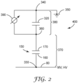
- the primary capacitor of the sensored insulation plug described herein is operable as a high-voltage capacitor in a voltage divider, which in use is electrically connected between the connection element on elevated voltage and electrical ground, for sensing the elevated voltage of the connection element of the separable connector.
- the voltage divider comprises, in its high-voltage portion, the primary capacitor of the sensored insulation plug described herein.
- the voltage divider may be a capacitive voltage divider.
- both its high-voltage portion and its low-voltage portion each consist of one or more capacitors, respectively, and are free of impedance elements of other types, such as resistors or inductances.
- the voltage divider is a mixed voltage divider, in which the high-voltage portion may comprise, beyond the primary capacitor, an inductance or a resistor, and in which the low-voltage portion comprises a capacitor and/or an inductance and/or a resistor.
- the high-voltage portion of a voltage divider is the portion that is electrically arranged between a signal contact, at which a divided voltage can be picked up, and a contact for connection to the voltage which is to be sensed.
- the low-voltage portion of the voltage divider is the portion that is electrically arranged between that signal contact and a contact for connection to electrical ground.
- the primary capacitor may be the only impedance element of the high-voltage portion of the voltage divider. In other words, there may be no other capacitor(s) and no other impedance elements electrically arranged between the elevated voltage and the signal contact of the voltage divider.
- the primary capacitor may be the first impedance element in an electrical chain of impedance elements of the voltage divider.
- the primary capacitor may be arranged electrically at the end of the chain and may be adapted to be electrically connected directly with the elevated voltage.
- the primary capacitor would thus be the impedance element of the voltage divider which "sees" the full elevated voltage on its high-voltage electrode.
- the primary capacitor may be directly electrically connected to the elevated voltage of the connection element, that is, the primary capacitor is electrically connected to the connection element without any intermediate element.
- the high-voltage electrode of the primary capacitor may be directly electrically connected to the elevated voltage, i.e. to the elevated voltage of the connection element.
- the high-voltage electrode of the primary capacitor may be directly electrically connected to the connection element. This direct electrical connection may be established, for example, through a contact piece, which is an electrically conductive mechanical element between the high-voltage electrode and the connection element of the separable connector.
- directly electrically connected and “direct electrical connection” as used herein refer to a fully conductive (ohmic) electrical connection between two elements, e.g. via a wire or via a conductive path on a PCB or via a conductive element, without any intermediate electrical component such as a resistor, a capacitor or an inductor, being arranged electrically between the two elements.
- the sensing electrode is shaped and arranged such as to be generally rotationally symmetric about the plug axis of the sensored insulation plug
- the high-voltage electrode is shaped and arranged such as to be generally rotationally symmetric about the plug axis of the sensored insulation plug.
- the high-voltage electrode and the sensing electrode may thus be arranged coaxially, or concentrically, with the sensing electrode being arranged around the high-voltage electrode.
- the sensing electrode being arranged around the high-voltage electrode implies that the sensing electrode, or at least an axial portion of the sensing electrode, is arranged radially outward from the high-voltage electrode and surrounds the high-voltage electrode.
- the sensing electrode of the primary capacitor is embedded in the plug body.
- a portion of the embedded sensing electrode, or the entire sensing electrode, may be in surface contact with the insulating material of the plug body.
- the sensing electrode may be electrically connected, or connectable, to a low-voltage capacitor, such that the primary capacitor and the low-voltage capacitor form a voltage divider for sensing the elevated voltage of a connection element of a separable connector.
- the primary capacitor may be comprised in, or may form, the high-voltage portion of the voltage divider, while the low-voltage capacitor may be comprised in, or may form, the low-voltage portion of the voltage divider.
- the sensored insulation plug according to the present disclosure may comprise a grounding contact for electrically connecting an element of the sensored insulation plug to electrical ground.
- the sensored insulation plug comprises a low-voltage capacitor of the voltage divider
- the sensored insulation plug may comprise a grounding contact for electrically connecting the low-voltage capacitor to electrical ground.
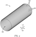
- the mesh of conductive wires comprised in the sensing electrode is a deformable mesh.
- deformation refers to a change in size or shape. While in theory everything is deformable, the deformable mesh is adapted to be deformed by forces exerted by a typical insulating material in liquid state flowing around the mesh when the sensored insulation plug is produced in a casting or molding process.
- the apertures extend through the deformable mesh in a thickness direction of the mesh.
- the thickness of the mesh may be, for example, between about 0,1 mm and about 2 mm, preferably between about 0,2 mm and about 1 mm. Thicker meshes tend to be less deformable and may add to weight of the sensored insulation plug more than necessary. Wires forming the mesh may have diameters, for example, of 0,05 mm or more, 0,2 mm or more, 0,5 mm or more, or 1,0 mm or more.
- the deformable mesh it is generally preferred for the deformable mesh to have more smaller apertures, as opposed to fewer larger apertures, as this is believed to enhance cohesion between portions of the insulating material on opposite sides of the mesh.
- the mesh of conductive wires forms one thousand or more apertures.
- a large number of apertures, like one thousand or more apertures, provides a large number of "bridges" between portions of the insulating material on opposite sides of the mesh and can thereby enhance cohesion and reduce the risk of delamination of insulating material at the sensing electrode.
- the size of the apertures it is also the number of apertures in the mesh of conductive wires which determines how well the portion of the casting material outside the mesh (i.e. radially outward of the mesh) is connected with the portion of the casting material inside the mesh (i.e. inside the tube formed by the tubular sensing electrode, radially inward from the mesh).
- more apertures are desirable but this needs to be balanced against the effect of reducing the surface of the sensing electrode by having more apertures, which typically reduces the capacitance of the primary capacitor.
- the deformable mesh is a mesh of stainless-steel wires of 0,2 mm wire thickness forming apertures of a size of about 0,1 mm between the wires.
- a suitable capacitance of the primary capacitor is in the order of 30 pF (Picofarad).
- further factors like the permittivity of the insulating material and the geometry of the electrodes must be considered, as is generally known.
- an electrode is considered embedded in the plug body if the plug body is cast or molded around the electrode.
- an element of the sensored insulation plug may be considered embedded in the plug body if a major portion, e.g. more than 90% or more than 95%, of its exterior surface is in surface contact with the insulating material. Surface contact, however, is not a prerequisite for being considered “embedded", as an embedded element may, for example, be arranged in a cavity of the plug body without being in surface contact with the insulating material.
- the high-voltage electrode of the primary capacitor may be embedded in the plug body.
- a portion of an embedded high-voltage electrode, or an entire embedded high-voltage electrode, may be in surface contact with the insulating material of the plug body.
- the sensored insulation plug according to the present disclosure further comprises a shield electrode of generally tubular shape, embedded in the plug body, arranged around, and enveloping, the sensing electrode.
- the shield electrode is arranged around the sensing electrode in order to help shield the sensing electrode of the primary capacitor against external electrical fields and thereby to improve the accuracy of the voltage sensing.
- the shield electrode may be held on a fixed voltage, e.g. on ground potential.
- the shield electrode may be electrically connected to the grounding contact.
- a shield electrode can help minimize the impact of external electrical fields on the sensing electrode, can reduce parasitic capacitances in the voltage divider in which the primary capacitor is comprised, and thereby can enhance the accuracy of the voltage sensing.
- the shield electrode may have a generally tubular shape.
- the tubular shape defines a length direction of the shield electrode.
- the shield electrode may be advantageously arranged such that its length direction extends in an axial direction of the plug body.
- the sensing electrode has a rotationally symmetric shape
- the shield electrode has a rotationally symmetric shape
- the shield electrode is arranged concentrically around the sensing electrode.
- the shield electrode may comprise a plurality of radial through-holes. During production of the sensored insulation plug as described herein, such through-holes or apertures may allow for liquid insulating material forming the plug body to enter more easily the space between the shield electrode and the sensing electrode, before the insulating material solidifies and forms the plug body.
- the shield electrode is a mesh of conductive wires, e.g. stainless steel wires or copper wires, similar to the wires described above for the deformable mesh of the sensing electrode.
- the sensing electrode is typically on a potential of a few volt, while the shield electrode is typically on ground potential.
- a major surface of the sensing electrode and a major surface of the shield electrode may thus be arranged relatively close to each other without risking an electrical discharge between them.
- the sensing electrode comprises the deformable mesh, upon deformation the mesh may contact the shield electrode mechanically and electrically, which would make voltage sensing impossible.
- an electrically insulating spacer layer may be arranged between the sensing electrode and the shield electrode.
- the spacer layer may be deformable by insulating material in liquid state flowing around the spacer layer before solidification of the insulating material.
- the insulating spacer layer may be, for example, a polymeric layer such as a layer of a polymeric film, or a layer of a nonwoven material.
- the spacer layer can be attached to the sensing electrode before the molding process.
- the spacer layer is attached to the mesh of the sensing electrode by an adhesive layer.
- the spacer layer comprises apertures for allowing flow of liquid insulation material through the spacer layer.
- the spacer layer comprises a layer of nonwoven material comprising porous apertures for allowing flow of liquid insulation material through the spacer layer.
- An example of a suitable material for a spacer layer comprising a layer of nonwoven material having porous apertures is a porous adhesive tape like, for example, 3M TM Micropore TM Surgical Tape, available from 3M Company, St. Paul, Minnesota, U.S.A.
- the spacer layer comprises a polymeric film having apertures for allowing flow of liquid insulation material through the spacer layer.
- the spacer layer comprises a polymeric foam tape having apertures for allowing flow of liquid insulation material through the spacer layer.
- the sensored insulation plug further comprises an electrically insulating spacer layer arranged radially between the shield electrode and the sensing electrode, wherein optionally the spacer layer comprises a layer of nonwoven material or a polymeric layer.
- the shield electrode may be rigid or it may be deformable.
- a deformable shield electrode may be made from, or comprise, for example, a conductive layer on a deformable foil or on a paper substrate.
- a deformable shield electrode may be made from, or comprise, for example, a deformable metal foil or a deformable metal sheet.
- a deformable shield electrode comprises a deformable stainless-steel foil, a deformable copper foil or a deformable aluminium foil.
- a deformable shield electrode may be comprised, for example, in a flexible circuit board, such as a flexible printed circuit board. Where the plug body is manufactured using a solidifiable insulating material, e.g.
- a deformable shield electrode in a casting process or molding process, can move during the solidification and any related movement of the insulating material.
- a deformable shield electrode can thus "follow" the moving insulating material as it flows, solidifies and shrinks. This may result in a lower risk of delamination between the shield electrode and the insulating material and in a lower risk of voids being generated in the plug body. Less voids generally means less risk of electrical discharges, making the sensored insulation plug more reliable.
- the shield electrode comprises a conductive layer arranged on an electrically insulating substrate.
- the shield electrode is formed by a conductive layer of a circuit board, e.g. of a printed circuit board ("PCB").
- the shield electrode is thus comprised in the circuit board.
- the shield electrode may be, for example, applied on a substrate of the circuit board.
- the conductive layer may be arranged on an outer surface of the circuit board, or it may be arranged within the circuit board.
- the circuit board may be of a generally tubular shape for the shield electrode to be of a generally tubular shape.
- the circuit board may be, for example, a rigid circuit board or a flexible circuit board.
- Rigid circuit boards are generally stiff, they often comprise an insulating substrate like an FR-2 or an FR-4 material, both widely known from printed circuit boards.
- the substrate of a circuit board provides mechanical strength to the circuit board.
- Flexible circuit boards can be flexed and bent, as is generally known. They comprise a flexible substrate like, for example, Kapton or a polyimide film on which conductive traces are applied that connect electronic elements mounted on the surface of the substrate.
- the sensored insulation plug according to the present disclosure further comprises a circuit board, embedded in the plug body and supporting the sensing electrode.
- a circuit board is a cost-effective means to support the sensing electrode and/or its mesh mechanically. Also, such a circuit board facilitates the making of electrical connections of the sensing electrode to other elements, such as the signal contact, which may be arranged on the circuit board.
Landscapes
- Physics & Mathematics (AREA)
- General Physics & Mathematics (AREA)
- Engineering & Computer Science (AREA)
- Power Engineering (AREA)
- Spectroscopy & Molecular Physics (AREA)
- Measuring Instrument Details And Bridges, And Automatic Balancing Devices (AREA)
- Investigating Or Analyzing Materials By The Use Of Electric Means (AREA)
Claims (16)
- Bouchon d'isolation à capteur (1) destiné à être inséré dans une cavité arrière (70) d'un connecteur séparable (10) moyenne tension ou haute tension dans un réseau de distribution d'énergie d'un réseau national, et utilisable pour isoler un élément de connexion (80) du connecteur séparable sur une tension élevée et pour détecter la tension élevée, le bouchon d'isolation à capteur comprenanta) un corps de bouchon (140) formé d'un matériau isolant solidifié (610), etb) un condensateur principal (150), utilisable en tant que condensateur haute tension dans un diviseur de tension (400) pour détecter la tension élevée, le condensateur principal ayanti) une électrode haute tension (160) pour une connexion électrique directe à la tension élevée ;ii) une électrode de détection (170) d'une forme tubulaire, intégrée dans le corps de bouchon (140), agencée autour de l'électrode haute tension, et comprenant une maille (570) de fils conducteurs (590) formant une pluralité d'ouvertures (600) entre les fils pour permettre à des parties du matériau isolant (610) sur des côtés opposés de la maille d'être mécaniquement reliées les unes aux autres par le matériau isolant (610) dans les ouvertures (600) tandis que le matériau isolant (610) se solidifie et ensuite ;iii) un diélectrique formé par une partie (180) du matériau isolant (610) agencé entre l'électrode de détection (170) et l'électrode haute tension (160), caractérisé en ce que la maille est une maille déformable, adaptée à être déformée par le matériau isolant (610) à l'état liquide s'écoulant autour de la maille avant une solidification du matériau isolant (610).
- Bouchon d'isolation à capteur selon la revendication 1, dans lequel au moins une ouverture (600) de la pluralité d'ouvertures (600) est remplie de matériau isolant (610) reliant mécaniquement les parties du matériau isolant (610) sur des côtés opposés de la maille (570) les unes aux autres.
- Bouchon d'isolation à capteur selon l'une quelconque des revendications précédentes, dans lequel la maille (570) de fils conducteurs (590) forme un millier ou plus d'ouvertures (600).
- Bouchon d'isolation à capteur selon l'une quelconque des revendications précédentes, dans lequel les fils (590) comprennent du cuivre, de l'argent, de l'or ou de l'acier inoxydable.
- Bouchon d'isolation à capteur selon l'une quelconque des revendications précédentes, dans lequel les fils (590) ont un diamètre compris entre 0,05 mm et 1 mm.
- Bouchon d'isolation à capteur selon l'une quelconque des revendications précédentes, dans lequel la maille (570) est une maille tissée ou une maille nouée ou une maille bouclée.
- Bouchon d'isolation à capteur selon l'une quelconque des revendications précédentes, dans lequel les ouvertures (600) ont des dimensions respectives comprises entre 0,05 mm et 2 mm, telles que mesurées dans l'extension la plus courte de chaque ouverture.
- Bouchon d'isolation à capteur selon l'une quelconque des revendications précédentes, dans lequel la maille (570) est une maille plastiquement déformable.
- Bouchon d'isolation à capteur selon l'une quelconque des revendications 1 à 7, dans lequel la maille (570) est une maille élastiquement déformable.
- Bouchon d'isolation à capteur selon l'une quelconque des revendications précédentes, dans lequel la maille (570) a une forme généralement cylindrique définissant une direction axiale (110) et des directions radiales (120) orthogonales à celle-ci, et dans lequel la maille (570) est adaptée à être déformée dans des directions radiales (120).
- Bouchon d'isolation à capteur selon l'une quelconque des revendications précédentes, dans lequel le matériau isolant (610) comprend une résine époxy et, éventuellement, une charge, telle que SiO2 ou Al2O3 ou un autre matériau inorganique électriquement isolant.
- Bouchon d'isolation à capteur selon l'une quelconque des revendications précédentes, comprenant en outre une électrode de blindage de forme généralement tubulaire, intégrée dans le corps de bouchon (140), agencée autour de l'électrode de détection (170) et l'enveloppant.
- Bouchon d'isolation à capteur selon la revendication 12, comprenant en outre une couche d'espacement électriquement isolante agencée radialement entre l'électrode de blindage et l'électrode de détection (170), dans lequel la couche d'espacement comprend éventuellement une couche de matériau non tissé ou une couche polymère.
- Bouchon d'isolation à capteur selon l'une quelconque des revendications précédentes, comprenant en outre une carte de circuit imprimé (500), intégrée dans le corps de bouchon (140) et supportant l'électrode de détection (170).
- Réseau de distribution d'énergie destiné à distribuer de l'énergie électrique à moyennes ou hautes tensions, le réseau comprenanta) un connecteur séparable (10) ayant une cavité arrière (70) et un élément de connexion (80) sous tension élevée lorsqu'il est utilisé et accessible à travers la cavité arrière (70) ; etb) un bouchon d'isolation à capteur (1) selon l'une quelconque des revendications précédentes, insérée dans la cavité arrière (70) pour isoler l'élément de connexion (80) et pour détecter la tension élevée de l'élément de connexion (80), dans lequel l'électrode haute tension (160) est directement connectée électriquement à l'élément de connexion (80).
- Processus de fabrication d'un bouchon d'isolation à capteur (1) destiné à être inséré dans une cavité arrière (70) d'un connecteur séparable (10) moyenne tension ou haute tension dans un réseau de distribution d'énergie d'un réseau national, et utilisable pour isoler un élément de connexion (80) du connecteur séparable sur une tension élevée et pour détecter la tension élevée, le processus comprenant les étapes, dans cet ordre, consistant àa) fournir une électrode haute tension (160) d'un condensateur principal (150) pour une connexion électrique directe à la tension élevée, et une électrode de détection (170) du condensateur principal (150), ayant une forme tubulaire et comprenant une maille (570) de fils conducteurs (590) formant une pluralité d'ouvertures (600) entre les fils (590) pour permettre aux parties d'un matériau isolant (610) sur des côtés opposés de la maille d'être mécaniquement reliées les unes aux autres par un matériau isolant dans les ouvertures (600) tandis que le matériau isolant se solidifie et par la suite, dans lequel la maille (570) est une maille déformable (570), adaptée à être déformée par un matériau isolant à l'état liquide s'écoulant autour de la maille avant une solidification du matériau isolant ;b) agencer l'électrode de détection (170) autour de l'électrode haute tension (160) ;c) réaliser le moulage ou le coulage d'un matériau isolant liquide (610) autour de l'électrode haute tension (160) et de l'électrode de détection (170) pour former un corps de bouchon (140) du bouchon d'isolation à capteur (1), de telle sorte que l'électrode de détection (170) est intégrée dans le matériau isolant (610) et de telle sorte qu'une partie (180) du matériau isolant forme un diélectrique entre l'électrode de détection (170) et l'électrode haute tension (160) ; etd) solidifier le matériau isolant (610).
Priority Applications (3)
| Application Number | Priority Date | Filing Date | Title |
|---|---|---|---|
| EP20208737.5A EP4001928B1 (fr) | 2020-11-19 | 2020-11-19 | Bouchon d'isolation à capteur |
| PCT/IB2021/059899 WO2022106937A1 (fr) | 2020-11-19 | 2021-10-26 | Embout isolant à capteur |
| US18/249,665 US12553921B2 (en) | 2020-11-19 | 2021-10-26 | Sensored insulation plug |
Applications Claiming Priority (1)
| Application Number | Priority Date | Filing Date | Title |
|---|---|---|---|
| EP20208737.5A EP4001928B1 (fr) | 2020-11-19 | 2020-11-19 | Bouchon d'isolation à capteur |
Publications (2)
| Publication Number | Publication Date |
|---|---|
| EP4001928A1 EP4001928A1 (fr) | 2022-05-25 |
| EP4001928B1 true EP4001928B1 (fr) | 2025-06-25 |
Family
ID=73497678
Family Applications (1)
| Application Number | Title | Priority Date | Filing Date |
|---|---|---|---|
| EP20208737.5A Active EP4001928B1 (fr) | 2020-11-19 | 2020-11-19 | Bouchon d'isolation à capteur |
Country Status (3)
| Country | Link |
|---|---|
| US (1) | US12553921B2 (fr) |
| EP (1) | EP4001928B1 (fr) |
| WO (1) | WO2022106937A1 (fr) |
Families Citing this family (3)
| Publication number | Priority date | Publication date | Assignee | Title |
|---|---|---|---|---|
| EP4099024B1 (fr) | 2021-06-04 | 2025-03-19 | 3M Innovative Properties Company | Bouchon d'isolation à capteur avec contact de détection |
| EP4304029A1 (fr) * | 2022-07-07 | 2024-01-10 | 3M Innovative Properties Company | Bouchon d'isolation et procédé d'installation associé |
| EP4711773A1 (fr) * | 2024-09-16 | 2026-03-18 | 3M Innovative Properties Company | Fiche isolante à capteur avec capteur de température |
Citations (1)
| Publication number | Priority date | Publication date | Assignee | Title |
|---|---|---|---|---|
| US20160245845A1 (en) * | 2013-09-30 | 2016-08-25 | Green Seas Ventures, Ltd | Capacitive sensor to sense an electric field, system and method to obtain it |
Family Cites Families (18)
| Publication number | Priority date | Publication date | Assignee | Title |
|---|---|---|---|---|
| US3513253A (en) * | 1968-07-24 | 1970-05-19 | Westinghouse Electric Corp | Cast condenser bushing having tubular metal coated mesh plates |
| DE4424072C1 (de) | 1994-07-08 | 1996-01-25 | Rheydt Kabelwerk Ag | Steckendverschluß |
| DE19547120A1 (de) * | 1995-12-16 | 1997-06-19 | Sachsenwerk Ag | Elektrode |
| US6031368A (en) | 1996-09-12 | 2000-02-29 | S&C Electric Company | Sensing apparatus for cable termination devices in power distribution systems |
| IT1292447B1 (it) * | 1997-07-01 | 1999-02-08 | Sace Spa | Isolatore passante con schermatura del campo elettrico,particolarmente per quadri di media e alta tensione |
| US20050082160A1 (en) | 2003-10-15 | 2005-04-21 | Sharper Image Corporation | Electro-kinetic air transporter and conditioner devices with a mesh collector electrode |
| JP5918775B2 (ja) * | 2010-11-16 | 2016-05-18 | コーニンクレッカ フィリップス エヌ ヴェKoninklijke Philips N.V. | 誘電体バリア放電ランプデバイス、及び、誘電体バリア放電ランプデバイスが設けられた光学流体処理デバイス |
| US9256311B2 (en) * | 2011-10-28 | 2016-02-09 | Atmel Corporation | Flexible touch sensor |
| EP2605416B1 (fr) | 2011-12-16 | 2014-06-25 | Arteche Lantegi Elkartea, S.A. | Dispositif de couplage de haute tension |
| US10125422B2 (en) * | 2013-03-27 | 2018-11-13 | Applied Materials, Inc. | High impedance RF filter for heater with impedance tuning device |
| US20180100878A1 (en) * | 2016-10-07 | 2018-04-12 | Cooper Technologies Company | Sensing device for an electrical system |
| KR102567205B1 (ko) * | 2017-05-17 | 2023-08-14 | 쓰리엠 이노베이티브 프로퍼티즈 컴파니 | 고전압 분리가능 커넥터를 위한 별개의 커패시터를 갖는 센서 |
| US11567031B2 (en) * | 2017-09-08 | 2023-01-31 | Oakland University | Selective real-time gas sensing |
| IT201800004114A1 (it) * | 2018-03-30 | 2019-09-30 | Green Seas Ventures Ltd C/O Citco B V I Ltd | Sistema costruttivo afferente un sensore capacitivo di tensione |
| EP3824299A1 (fr) * | 2018-07-17 | 2021-05-26 | 3M Innovative Properties Company | Capteur avec élément isolant pour connecteurs haute tension séparables |
| CN112771388A (zh) | 2018-10-03 | 2021-05-07 | 3M创新有限公司 | 用于高电压可分离连接器的测试点电压传感器 |
| US20220118150A1 (en) * | 2020-10-21 | 2022-04-21 | Nano And Advanced Materials Institute Limited | Multi-functional plasma driven catalyst system |
| EP4163646B1 (fr) | 2021-10-07 | 2025-02-19 | 3M Innovative Properties Company | Bouchon d'isolation à capteur |
-
2020
- 2020-11-19 EP EP20208737.5A patent/EP4001928B1/fr active Active
-
2021
- 2021-10-26 WO PCT/IB2021/059899 patent/WO2022106937A1/fr not_active Ceased
- 2021-10-26 US US18/249,665 patent/US12553921B2/en active Active
Patent Citations (1)
| Publication number | Priority date | Publication date | Assignee | Title |
|---|---|---|---|---|
| US20160245845A1 (en) * | 2013-09-30 | 2016-08-25 | Green Seas Ventures, Ltd | Capacitive sensor to sense an electric field, system and method to obtain it |
Also Published As
| Publication number | Publication date |
|---|---|
| WO2022106937A1 (fr) | 2022-05-27 |
| EP4001928A1 (fr) | 2022-05-25 |
| US12553921B2 (en) | 2026-02-17 |
| US20230305039A1 (en) | 2023-09-28 |
Similar Documents
| Publication | Publication Date | Title |
|---|---|---|
| US12553921B2 (en) | Sensored insulation plug | |
| US10955442B2 (en) | Elastic sleeve for a power conductor | |
| EP3913379A1 (fr) | Ensemble condensateur | |
| US20090288878A1 (en) | Bushing and a method for producing the same | |
| US20200174042A1 (en) | High-voltage impedance assembly | |
| EP3862760B1 (fr) | Composant isolé d'un capteur de tension | |
| US3394455A (en) | Method of constructing cast electrical bushings | |
| US12603458B2 (en) | Sensored insulation plug | |
| WO2019229694A1 (fr) | Capteur de tension | |
| US3627906A (en) | Electrical condenser bushing assembly | |
| WO2018115027A1 (fr) | Douille à électronique intégrée | |
| KR100748768B1 (ko) | 디바이스, 부분 방전 분석 커플링 디바이스 및 디바이스 제조 방법 | |
| EP4123316B1 (fr) | Douille avec capteur intégré | |
| EP4099024B1 (fr) | Bouchon d'isolation à capteur avec contact de détection | |
| EP4177614B1 (fr) | Douille à capteur | |
| EP3611518A1 (fr) | Tapis détecteur | |
| CN115280433A (zh) | 电容式套管 |
Legal Events
| Date | Code | Title | Description |
|---|---|---|---|
| PUAI | Public reference made under article 153(3) epc to a published international application that has entered the european phase |
Free format text: ORIGINAL CODE: 0009012 |
|
| STAA | Information on the status of an ep patent application or granted ep patent |
Free format text: STATUS: THE APPLICATION HAS BEEN PUBLISHED |
|
| AK | Designated contracting states |
Kind code of ref document: A1 Designated state(s): AL AT BE BG CH CY CZ DE DK EE ES FI FR GB GR HR HU IE IS IT LI LT LU LV MC MK MT NL NO PL PT RO RS SE SI SK SM TR |
|
| STAA | Information on the status of an ep patent application or granted ep patent |
Free format text: STATUS: REQUEST FOR EXAMINATION WAS MADE |
|
| 17P | Request for examination filed |
Effective date: 20221122 |
|
| RBV | Designated contracting states (corrected) |
Designated state(s): AL AT BE BG CH CY CZ DE DK EE ES FI FR GB GR HR HU IE IS IT LI LT LU LV MC MK MT NL NO PL PT RO RS SE SI SK SM TR |
|
| STAA | Information on the status of an ep patent application or granted ep patent |
Free format text: STATUS: EXAMINATION IS IN PROGRESS |
|
| 17Q | First examination report despatched |
Effective date: 20240202 |
|
| GRAP | Despatch of communication of intention to grant a patent |
Free format text: ORIGINAL CODE: EPIDOSNIGR1 |
|
| STAA | Information on the status of an ep patent application or granted ep patent |
Free format text: STATUS: GRANT OF PATENT IS INTENDED |
|
| INTG | Intention to grant announced |
Effective date: 20250324 |
|
| RIN1 | Information on inventor provided before grant (corrected) |
Inventor name: GUNJACA, MIRCO Inventor name: MILEK, MARTIN ANDREAS Inventor name: REEKEN, RAINER Inventor name: BUND, CHRISTINE BRIGITTE Inventor name: STOLLWERCK, GUNTHER Inventor name: GRAVERMANN, MARK |
|
| P01 | Opt-out of the competence of the unified patent court (upc) registered |
Free format text: CASE NUMBER: APP_15622/2025 Effective date: 20250331 |
|
| GRAS | Grant fee paid |
Free format text: ORIGINAL CODE: EPIDOSNIGR3 |
|
| GRAA | (expected) grant |
Free format text: ORIGINAL CODE: 0009210 |
|
| STAA | Information on the status of an ep patent application or granted ep patent |
Free format text: STATUS: THE PATENT HAS BEEN GRANTED |
|
| AK | Designated contracting states |
Kind code of ref document: B1 Designated state(s): AL AT BE BG CH CY CZ DE DK EE ES FI FR GB GR HR HU IE IS IT LI LT LU LV MC MK MT NL NO PL PT RO RS SE SI SK SM TR |
|
| REG | Reference to a national code |
Ref country code: GB Ref legal event code: FG4D |
|
| REG | Reference to a national code |
Ref country code: CH Ref legal event code: EP |
|
| REG | Reference to a national code |
Ref country code: CH Ref legal event code: EP |
|
| REG | Reference to a national code |
Ref country code: IE Ref legal event code: FG4D |
|
| REG | Reference to a national code |
Ref country code: DE Ref legal event code: R096 Ref document number: 602020053229 Country of ref document: DE |
|
| PG25 | Lapsed in a contracting state [announced via postgrant information from national office to epo] |
Ref country code: FI Free format text: LAPSE BECAUSE OF FAILURE TO SUBMIT A TRANSLATION OF THE DESCRIPTION OR TO PAY THE FEE WITHIN THE PRESCRIBED TIME-LIMIT Effective date: 20250625 |
|
| REG | Reference to a national code |
Ref country code: LT Ref legal event code: MG9D |
|
| PG25 | Lapsed in a contracting state [announced via postgrant information from national office to epo] |
Ref country code: NO Free format text: LAPSE BECAUSE OF FAILURE TO SUBMIT A TRANSLATION OF THE DESCRIPTION OR TO PAY THE FEE WITHIN THE PRESCRIBED TIME-LIMIT Effective date: 20250925 Ref country code: GR Free format text: LAPSE BECAUSE OF FAILURE TO SUBMIT A TRANSLATION OF THE DESCRIPTION OR TO PAY THE FEE WITHIN THE PRESCRIBED TIME-LIMIT Effective date: 20250926 |
|
| PG25 | Lapsed in a contracting state [announced via postgrant information from national office to epo] |
Ref country code: BG Free format text: LAPSE BECAUSE OF FAILURE TO SUBMIT A TRANSLATION OF THE DESCRIPTION OR TO PAY THE FEE WITHIN THE PRESCRIBED TIME-LIMIT Effective date: 20250625 |
|
| PG25 | Lapsed in a contracting state [announced via postgrant information from national office to epo] |
Ref country code: HR Free format text: LAPSE BECAUSE OF FAILURE TO SUBMIT A TRANSLATION OF THE DESCRIPTION OR TO PAY THE FEE WITHIN THE PRESCRIBED TIME-LIMIT Effective date: 20250625 |
|
| PG25 | Lapsed in a contracting state [announced via postgrant information from national office to epo] |
Ref country code: RS Free format text: LAPSE BECAUSE OF FAILURE TO SUBMIT A TRANSLATION OF THE DESCRIPTION OR TO PAY THE FEE WITHIN THE PRESCRIBED TIME-LIMIT Effective date: 20250925 |
|
| PG25 | Lapsed in a contracting state [announced via postgrant information from national office to epo] |
Ref country code: LV Free format text: LAPSE BECAUSE OF FAILURE TO SUBMIT A TRANSLATION OF THE DESCRIPTION OR TO PAY THE FEE WITHIN THE PRESCRIBED TIME-LIMIT Effective date: 20250625 |
|
| REG | Reference to a national code |
Ref country code: NL Ref legal event code: MP Effective date: 20250625 |
|
| PG25 | Lapsed in a contracting state [announced via postgrant information from national office to epo] |
Ref country code: NL Free format text: LAPSE BECAUSE OF FAILURE TO SUBMIT A TRANSLATION OF THE DESCRIPTION OR TO PAY THE FEE WITHIN THE PRESCRIBED TIME-LIMIT Effective date: 20250625 |
|
| PG25 | Lapsed in a contracting state [announced via postgrant information from national office to epo] |
Ref country code: PT Free format text: LAPSE BECAUSE OF FAILURE TO SUBMIT A TRANSLATION OF THE DESCRIPTION OR TO PAY THE FEE WITHIN THE PRESCRIBED TIME-LIMIT Effective date: 20251027 |
|
| REG | Reference to a national code |
Ref country code: AT Ref legal event code: MK05 Ref document number: 1806968 Country of ref document: AT Kind code of ref document: T Effective date: 20250625 |
|
| PG25 | Lapsed in a contracting state [announced via postgrant information from national office to epo] |
Ref country code: IS Free format text: LAPSE BECAUSE OF FAILURE TO SUBMIT A TRANSLATION OF THE DESCRIPTION OR TO PAY THE FEE WITHIN THE PRESCRIBED TIME-LIMIT Effective date: 20251025 |
|
| PGFP | Annual fee paid to national office [announced via postgrant information from national office to epo] |
Ref country code: DE Payment date: 20251022 Year of fee payment: 6 |
|
| PGFP | Annual fee paid to national office [announced via postgrant information from national office to epo] |
Ref country code: GB Payment date: 20251023 Year of fee payment: 6 |
|
| PG25 | Lapsed in a contracting state [announced via postgrant information from national office to epo] |
Ref country code: AT Free format text: LAPSE BECAUSE OF FAILURE TO SUBMIT A TRANSLATION OF THE DESCRIPTION OR TO PAY THE FEE WITHIN THE PRESCRIBED TIME-LIMIT Effective date: 20250625 Ref country code: SM Free format text: LAPSE BECAUSE OF FAILURE TO SUBMIT A TRANSLATION OF THE DESCRIPTION OR TO PAY THE FEE WITHIN THE PRESCRIBED TIME-LIMIT Effective date: 20250625 |
|
| PGFP | Annual fee paid to national office [announced via postgrant information from national office to epo] |
Ref country code: IT Payment date: 20251022 Year of fee payment: 6 |
|
| PGFP | Annual fee paid to national office [announced via postgrant information from national office to epo] |
Ref country code: FR Payment date: 20251022 Year of fee payment: 6 |
|
| PG25 | Lapsed in a contracting state [announced via postgrant information from national office to epo] |
Ref country code: CZ Free format text: LAPSE BECAUSE OF FAILURE TO SUBMIT A TRANSLATION OF THE DESCRIPTION OR TO PAY THE FEE WITHIN THE PRESCRIBED TIME-LIMIT Effective date: 20250625 |
|
| PG25 | Lapsed in a contracting state [announced via postgrant information from national office to epo] |
Ref country code: PL Free format text: LAPSE BECAUSE OF FAILURE TO SUBMIT A TRANSLATION OF THE DESCRIPTION OR TO PAY THE FEE WITHIN THE PRESCRIBED TIME-LIMIT Effective date: 20250625 |
|
| PG25 | Lapsed in a contracting state [announced via postgrant information from national office to epo] |
Ref country code: EE Free format text: LAPSE BECAUSE OF FAILURE TO SUBMIT A TRANSLATION OF THE DESCRIPTION OR TO PAY THE FEE WITHIN THE PRESCRIBED TIME-LIMIT Effective date: 20250625 |
|
| PG25 | Lapsed in a contracting state [announced via postgrant information from national office to epo] |
Ref country code: SK Free format text: LAPSE BECAUSE OF FAILURE TO SUBMIT A TRANSLATION OF THE DESCRIPTION OR TO PAY THE FEE WITHIN THE PRESCRIBED TIME-LIMIT Effective date: 20250625 |
|
| PG25 | Lapsed in a contracting state [announced via postgrant information from national office to epo] |
Ref country code: ES Free format text: LAPSE BECAUSE OF FAILURE TO SUBMIT A TRANSLATION OF THE DESCRIPTION OR TO PAY THE FEE WITHIN THE PRESCRIBED TIME-LIMIT Effective date: 20250625 |
|
| PG25 | Lapsed in a contracting state [announced via postgrant information from national office to epo] |
Ref country code: RO Free format text: LAPSE BECAUSE OF FAILURE TO SUBMIT A TRANSLATION OF THE DESCRIPTION OR TO PAY THE FEE WITHIN THE PRESCRIBED TIME-LIMIT Effective date: 20250625 |
|
| PG25 | Lapsed in a contracting state [announced via postgrant information from national office to epo] |
Ref country code: DK Free format text: LAPSE BECAUSE OF FAILURE TO SUBMIT A TRANSLATION OF THE DESCRIPTION OR TO PAY THE FEE WITHIN THE PRESCRIBED TIME-LIMIT Effective date: 20250625 |
|
| PLBE | No opposition filed within time limit |
Free format text: ORIGINAL CODE: 0009261 |
|
| STAA | Information on the status of an ep patent application or granted ep patent |
Free format text: STATUS: NO OPPOSITION FILED WITHIN TIME LIMIT |